Workshop Furniture
Woodworker’s Tool Chest
A woodworker’s first job, when he has gained enough skill, should be the creation of a good tool chest. This will offer a chance to practice using a range of tools, and the chest itself will keep those tools under lock and key when not in use. An ideal tool box should have a specific place for everything, as the chest illustrated by Figure 98 does. The letter references in Figures 98 and 100 are:
- A. bottom plinth
- B. top plinth
- c. rim round lid
- D. compartment for bead-planes, plough, etc.
- E. compartment for various tools, planes, etc.
- F. compartment for saws
- K. bottom till
- J. second till
- H. top till
- L. sliding-board to cover compartment E
- M. cleats to hold division between E and F
- N. cleats to hold division between D and E
- P. runners for sliding-board L
- R. runners for tills
- s. runners for tills K
The length of the chest must be sufficient to accommodate a rip-saw, so the chest is 33 inches long internally; and if it is made 20 inches wide by 21 inches deep, you will find it convenient for all purposes. For the outside case, use white deal no less than 1 inch thick. In gluing up the front, back, and ends to obtain the necessary width, tongue and dowel the joints, the former being the better method. In dovetailing the framework of the chest, make the pins small, and have them no more than 1½ inches apart; make sure that the joints in the front and back do not come immediately opposite those in the ends, or at some future time the chest may break in two. Figure 99 is a transverse section through the chest, Figures 100 to 103 show the details of construction. The plinths A and B run all round the chest, and are 6 inches and 2½ inches wide, respectively, and 1 inch thick, with the top edge of A and the bottom of B finished with a plain bevel; the tip edge of a ¼-inch bead being worked on it also. The plinths may be mitered at the corners, but it is better to dovetail them, and so obtain extra strength and good appearance. The plinth B is kept down about ¾ inch from the top of the chest to form a rebate for the lid to shut upon. The bottom of the chest is formed with boards 1 inch thick, tongued and grooved, and nailed on crossways—that is, the grain runs from front to back of the chest. The lid also is of 1 inch deal, with the joints tongued and grooved, and the ends clamped. It overhangs the chest all round in about  inch, and is hung with a pair of strong brass butts, and the self-acting spring lock is put on; then the rim c can be dovetailed together at the corners, and nailed to front and ends. This should result in a good fit where the rim of the lid meets the plinth B. Now you have finished the skeleton of the chest.
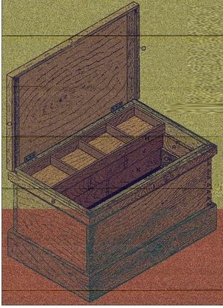
Figure 98—Tool Chest
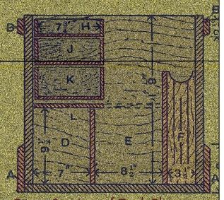
Figure 99—Cross Section of Tool Chest
Tool Chest Partitions
For the inside fittings of the tool chest use good yellow deal or pine, which you can finish by staining, although sometimes a more fancy wood is used. From Figure 99 it is seen that the chest is divided in its width into three parts: D is for bead-planes, plough, etc.; this is 7 inches wide, and is covered by the sliding tills; E holds miscellaneous tools, best planes, or anything not in everyday use; and F (3½ inches wide inside) is the saw till. These are divided by the two partitions shown, that between D and E are 9 inches high, and between E and F are 14 inches The three tills H, J, and K slide to and fro to give access to compartments beneath, and when in place at the back of the chest form a covering for compartment D; and a sliding-board beneath the tills, when pulled out as shown by dotted lines in Figure 99, covers compartment E. The bench-planes, which are in everyday use, can be packed away on the sliding-board between the tills and the highest partition. Figure 100 shows one end of the chest with the cleats about 1 inch wide by ½ inch thick; between these the partitions fit. The cleats holding the partition between E and F are fixed first, ½ inch apart, and are as shown at M M (Figure 100), the one nearer the back of the chest being continued nearly to the top, the other, nearer the front, stopping at the same height as the partition, namely 14 inches. The cleats N must be 8½ inches high from the bottom of the chest, and ¾ inch apart. The back partitions having been placed in position, fix the ledges P, with their top edges 9½ inches from the bottom of the chest; then they run from the back to the long upright cleat M, and on them works the sliding-board L, 9 inches by ¾ inch; this is clamped at the ends for the sake of strength and to make it slide more easily. It must be a good fit endways to avoid jamming against the ends of the chest. The runners for the tills (Figure 101) are made long enough to reach from the back of the chest to the long upright cleat M (Figure 100), and should be made of hard wood. The principle piece R, which forms the runners for the two top tills, is 7½ inches wide by 1 inch thick, rebated to half its thickness at o for a depth of 3¼ inches. A piece of hard wood s, 1½ inches by ½ inch is screwed on to the thick edge of R, and forms the runner for the bottom till. These runners can be fixed in position one on each end of the chest, leaving about ⅛ inch clearance between the bottoms and the top of sliding board L. The partition between compartments E and F can be made and fitted between the cleats M M; along its upper side is a strip of 1½ inches by ½ inch deal, cut to fit between the cleats on each end of the chest, fixed level with the top edge on the side nearest the front of the chest and packed off about  inch. The slot thus formed can be used as a rack for squares, the stocks resting on top of the partition, and the blades hanging down out of the way inside the saw till.
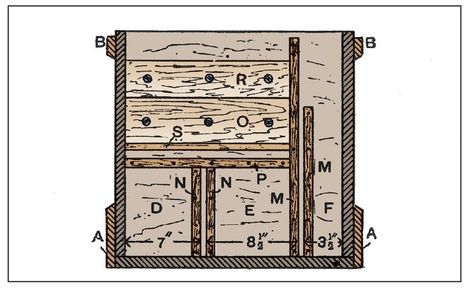
Figure 100—End of Tool Chest with Cleats and Runners
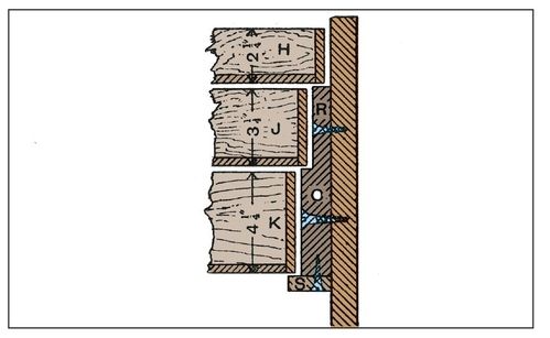
Figure 101—Section of Tool Chest Till Runners
Racks for Saws and Chisels
The saw racks in the chest, as shown in Figures 102 and 103, are 14 inches long, 3½ inches wide, and 1 inch thick, shaped at the top ends. Each has three slots, or rather, saw kerfs, and in one rack (Figure 102) the middle kerf runs from the top to within 3 inches of the bottom, the others stopping the same distance from the bottom, and about 1½ inches from the top. In the other racks (Figure 103) the middle slot is stopped at both top and bottom, the others being open at the top end. These two racks are fixed at about 8 inches from each end by screwing through the horn at the top of each to the front of the chest. The partition being then put into its place, screws can be put through it into each saw-rack, which will hold all in place. When placing the saws in the racks, the points are inserted in the closed slots of racks, and the handle ends dropped into the open slots, two saws pointing one way and one the opposite way. To take chisels, a piece of hard wood 2 feet long, 1 inch square, with a series of notches 1 inch apart cut into it wide enough to take the tools, can be screwed to the front of the chest just above the top of the partition; this leaves an equal space at each end to allow the hand to be inserted to remove saws form the rack. The handles of the larger chisels will be just inside the front of the chest, convenient for withdrawal when wanted for use, and the blades with hang out of the way in the saw till.
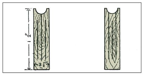
Figures 102 and Figures 103—Saw Racks.
Tool Chest Tills
The three sliding tills for the inside of the chest are all that remains. They will all be 9 inches wide outside, but varied in depth, as shown by Figure 101, on which dimensions are marked. They should be of ¾ inch stuff, with ½ inch bottoms and divisions, the rims dovetailed together, and the fronts and back rebated to receive the bottoms, the grain of which should run across the width of the tills; and at each end the bottom should be of hard wood. The divisions should be trenched into the sides, forming in K, J, and H two, three, and four compartments respectively. One of the bottom divisions should be fitted up for the brace and bits, with racks for the bits fitted round the brace. Other divisions can be fitted with racks for small chisels, gouges, gimlets, bradawls, and various other tools, the aim throughout being to have a place for all, so that nothing can roll about and get damaged. Turn-buttons to take the tenon and dovetail saws can be screwed on to the under-side of the lid, so that when it is closed they will be in position between the top till and the front of the chest. The purpose of the cleat M, running up higher than its fellow, is to stop the tills from coming into collision with the stocks of squares when in their rack. The sliding-board L can be grasped underneath with the fingers when it is desired to draw it forward, and it should have a couple of thumb-holes cut in its top as a means of pushing it back. Each till should have a pair of flush-rings inserted in the front, so that either can be pulled forward and its contents exposed without the necessity of touching the others. A strong iron handle on each end of chest will now make it complete.
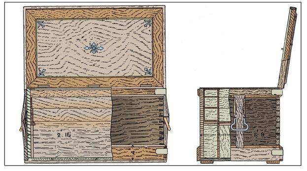
Figure 104 and Figure 105—Elevation and Sections of Tool Chest
Tool Chest Lid
For the lid a piece of pine 2 feet, 11½ inches by 1 foot, 9 inches by ⅞ inch must be made. In some cases the ends are clamped, but the lid will stand better if properly cross battened. When the lid has been planed, the inside should be roughed with the toothing plane and two or three battens screwed across the grain on the other side to prevent warping. The inside can then be veneered with a center panel and a banding about 2½ inches wide as shown by Figure 104. Use Spanish mahogany veneer for the center panel, and a light or dark fancy wood veneer for the line, which may be about ⅜ inch wide, and for the center and corner inlays. Some workers veneer the center, and have a margin about ¼ inch thick, as shown on the underside of Figure 106, a planted molding being used for covering the edge of the veneer. When the glue is thoroughly dry the battens may be removed from the back, and the mahogany plinth A (Figure 106) screwed to the front and the ends; the parts seen when the lid is open should be polished. Pieces of 1¼ inch by ⅛ inch hoop iron B (Figure 106) can now be screwed round the top of the lid to protect the edges, and the space between filled in with ⅜ inch deal boards c, screwed across the grain of the lid; the ends can be rounded down to the hoop iron to strengthen it and also to prevent warping. The lid can now be hung with three 2¾ inches by ¾ inch brass butt hinges as shown in Figure 104. A strong lock can then be let in the front and a sash lid D (Figure 106) screwed to the plinth at the front. Figure 105 shows that the top plinth at the back is kept above that of the sides and front, to support the lid when open. In addition to the lock, one or two holes should be bored through the lid at both ends and countersunk in the hoop iron, so that the lid can be screwed down for traveling, etc. The outside corners of the chest should be protected with angle plates on the plinth as shown on the right-hand side of Figures 104 and 105, and these may be made by bending pieces of 1½ inches No. 16 b.w.g. iron 6 inches long to aright angle, punching the holes and countersinking for No. 10 screws.

Figure 106—Section through Front of Tool Chest Lid

Figure 107—Top Tray of Tool Chest
Inside Fittings of Tool Chest
For the interior fittings of the chest a small nest of drawers at the back is sometimes used, but some prefer trays, as shown, as the drawers are liable to stick if a tool gets misplaced. Also they take a lot of material and labor, and the drawers are most difficult to secure than trays when the chest is packed. The trays should be of ⅜ inch mahogany, dovetailed together like a drawer, the top trays being fitted with lids, as shown in Figure 107; the total depth over all is 2¼ inches. Figure 108 shows one of the lower trays, and these do not have lids. The cross divisions in the trays may be made to meet requirements, but the following plan of dividing is a good one: Top tray at the back, space 1 foot, 4 inches long at the center with divisions about 8 inches at each end; second tray, the same as the top; and the bottom tray, one division in the center. For the narrow trays, the top one may be divided the same as the top one at the back; the second tray, with a partition 7½ inches from one end; and the bottom tray, with a division 10½ inches from the opposite end to the tray above. The space in the chest below the trays may be divided longitudinally into three compartments. The boards to form the divisions are fixed to an upright piece of wood ⅝ inch thick, B, secured to the ends of the chest. This part of the text is just deep enough to take small planes placed on end. A saw rack may with advantage be fitted in the space under the front trays, and the center space is covered with a board A, which slides back under the back trays. The inside of the chest should be French-polished, and the outside should have three or four coats of good paint.

Figure 108—Second Tray of Tool Chest
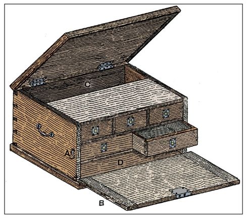
Figure 109—Tool Chest with Drawers
Packing Tool Chest for Transit
In packing the chest for traveling, the bottom divisions should be filled first, and the heaviest tools placed in the center portion. The slide can then be pulled over and fixed with a small screw at one end. The trays can then be filled, and secured either by means of strips fixed across the ends, or by filling the space between them with soft material that will not damage the polish. The lids of the top trays can then be fastened by placing across them two strips at the ends that will just fill up the space between the tops of the trays and the lid, when the latter can be locked and screwed.
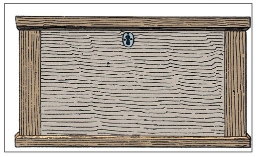
Figure 110—Front View of Tool Chest
Small Tool Chest with Drawers
For the small tool chest with drawers, shown in several views by Figure 109, a handy size is 1 foot, 9 inches by 1 foot, 2 inches by 1 foot deep. The sides, ends, bottom, and top are of red deal finishing about ¾ inch thick. The divisions are of ½ inch material, and the drawer fronts of ⅝ inch material. The sides, backs, and bottoms of the drawers are of ⅝ inch material, but of course these dimensions may be varied to meet your requirements. Figure 109 shows that the front is hinged on the bottom, so as to drop down and to allow of ready access to the drawers. To keep the front from twisting and warping, it must be clamped as shown, and when the front is closed up it is secured to the lid by a lock (see also Figure 110). In addition, a hook A (Figures 109 and 111) and eye B (Figure 111) may be used. The bottom is finished off with a plinth, which is rebated as illustrated in the section (Figure 112) will have extra strength. The lid should be stiffened by a 1¼ inches by ½ inch rim. The well c and the space D under the drawers will be found very useful for large tools.
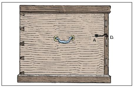
Figure 111—End View of Tool Chest
Utilizing Tool Chest Lids
The insides of tool chest lids are adapted readily to hold hand saws and tenon saws, the ends of which are held in wooden clips. The handle can be fastened by means of a button B, this method being just as suitable for hand saws as for the tenon saw shown. When the button is moved into position, it will allow for the saw to be taken out.
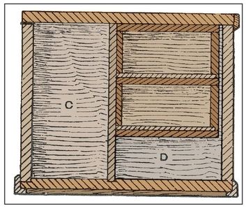
Figure 112—Cross Section of Tool Chest
Simple Tool Chest
The simple chest shown in longitudinal section by Figure 118 must be long enough to take the rip saw, and it is as light as possible consistent with strength. Figure 119 is a cross section. The yellow pine is ⅞ inch thick for the body, 1 inch for the lid, and ⅝ inch for the outside plinth and facings; the bottom is of ¾-inch red pine. The plinth has an ovolo molding on it, but you will commonly see an ogee molding. The top facing is in two parts, one being screwed to the edge of the lid and rounded on the top; the other one, upon which are run a bead and a chamfer, is merely nailed to the box. The body of the box is dovetailed and glued, but the plinth and top facing are mitered and nailed. The bottom has ploughed and cross-tongued joints waterproofed by painting with white lead. Clamp the top to prevent warping, and screw the facings on after the lid had been fitted to the size of the box. Battens of well painted red or yellow pine should be screwed to the under-side of the bottom, to keep the box clear of wetness. Figure 119 shows the inside arrangement. At the back, a space for smoothing planes, rebate planes, casements, etc., is formed by nailing fillets to the ends of the box, to which the pieces of pine A is screwed. Narrow fillets are nailed to the ends of the box outside of the piece A, and the piece B is screwed to them. A space is thus provided for the tenon saws and hatchet. The method o fixing the hand saws to the inside of the lid is shown by dotted lines in Figure 118, and is on the same principle as that already described. A piece of wood, the thickness of the saw handle, is fitted in the hole, and screwed to the lid. A piece of sheet brass to form a long button then is screwed to the block of wood; this button, when turned round as in Figure 118, prevents the handle of the saw from leaving the lid. The hardwood clip to hold the point of the saw has no recess for the back as there shown. The method of packing the chisels and gouges is seen in Figure 119. A small fillet, with a strip of leather glued to the top edge, is nailed to the bottom, and a thin piece of pine, projecting about 1 inch above the leather, is nailed to the fillet. This receives the points of the chisels and gouges. Another piece, with various sizes of holes cut out, is screwed about 3 inches or 4 inches up, to keep the top part steady. Figure 120 shows the piece with the holes checked out and a thin piece screwed to the front; this is much easier than mortising the holes. The tray c (Figures 118 and 119) is a box the whole length of the inside, lap dovetailed at the back. It is divided into various compartments (two small ones and a large one will be found very handy) by thin pieces of pine, either raggled into the front and back or merely butted and nailed. The bottom, which is ⅝ inches thick, is screwed up. It is very common to have a hardwood flap on the tray, as shown, but this can be dispensed with at will. A back stile is screwed to the back of the tray, and the flap is hinged to it. Fillets D are screwed to the ends of the box, on which the tray slides to and fro.
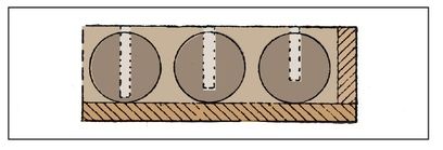
Figure 113—Cross Section of Part of Lid
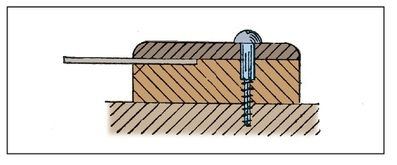
Figure 114—Try-Square Holder
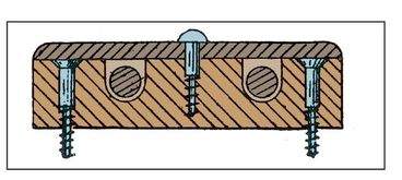
Figure 115—Holder for Pincers
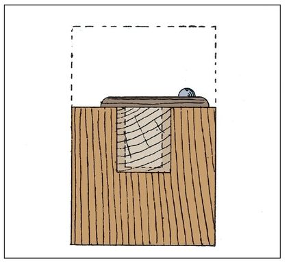
Figure 116—Elevation of Mallet Holder
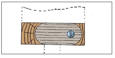
Figure 117—Plan of Mallet Holder
Tool Cabinet
You can see a useful tool cabinet with paneled doors and three drawers illustrated in Figure 121. It would have a neat appearance if it were made in oak or other hard wood and polished; or even if made of deal, if stained and varnished. The leading dimensions figured in the vertical section (Figure 122), and in the horizontal section (Figure 123) are only suggestive. The sides, top, and bottom are of ¾-inch material, grooved and tongued together, as indi-cated in Figure 124. The sides should also be rebated to receive the back, and grooved for shelf as shown in 123 and 124. The two divisions (separating the drawers) should be grooved into the shelf and bottom as shown. The back can be formed of three boards ⅝ inch thick, its upper part being sawn and smoothed to the shape shown in Figure 121. The front edges and ends of the top and bottom may be rounded. Fit all the parts of the case together, and finally secure them by gluing and nailing. Wood about ⅞ inch thick will be required for the stiles and rails of the doors; the panels may be about ⅜ inch thick. The doors should be mortised and tenoned together and ploughed to receive panels; they should be finished by being glued, wedged, planed off, fitted to the case, and rebated together (see Figures 121 and 123), after which they can be hung with 3-inch butts. The drawers should be properly dovetailed; ¾-inch wood will do for the fronts, and ½-inch for the sides, backs, and bottoms. Brass flush drop handles will be best for the drawer fronts. Two small bolts secure the door on the left, and there is a 2½-inch cut cupboard lock on the right-hand door. The cabinet could be fixed to a wall with four holdfasts, or it might rest upon a couple of brackets or other similar arrangement. The inside can be fitted with racks, according to requirements.
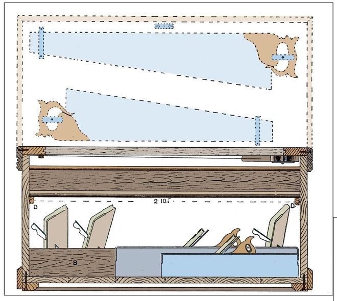
Figure 118—Section of Simple Tool Chest
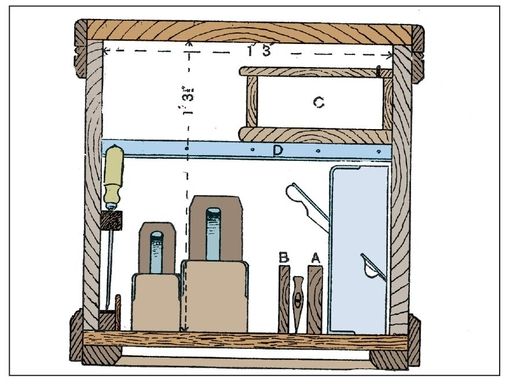
Figure 119—Cross Section of Simple Tool Chest
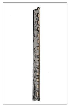
Figure 120—Tool Chest Chisel Rack
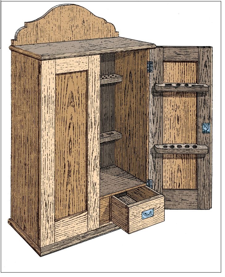
Figure 121—Tool Cabinet
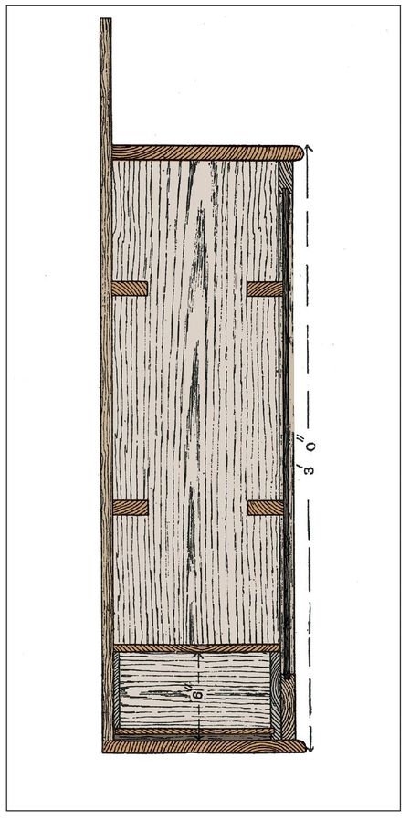
Figure 122—Vertical Section of Tool Cabinet
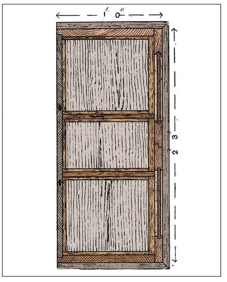
Figure 123—Horizontal Section of Tool Cabinet
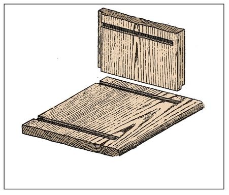
Figure 124—Housing for Sides of Tool Cabinet
Strong Stool or Work Bench
A stool or bench is useful for various purposes, both in the household and in the workshop. It can, without much trouble, be taken to pieces, so that it may be conveniently stowed away when not in use. When using the stool for domestic use, the sizes of the timber should be about 2 inches by 2 inches for all parts of the frame. The top consists simply of a slab about 1 inch thick, having four holes bored in it to fit over the dowels or pins A. Suitable measurements for the finished article are: Length of top, 2 feet, 9 inches ; width of top, 1 foot, 3 inches; and height from ground, about 1 foot, 10 inches. For a work bench, however, you can increase these measurements, being sure to increase the framework proportionately, and the top, instead of fitting over pins or dowels, should be secured with nuts and bolts. The spread of the legs at the bottom should be such that they would occupy the four corners of a rectangle, equal and similar to that of the top; this prevents all tilting, and secures stability for the bench, a point that is often overlooked. Before marking out the framework, make a mold; take a piece of wood, about ⅜ inch thick, and square off one end, as at B, and make the other cut to the desired bevel or splay of the legs, as shown at A; a narrow strip is fastened to the edge, so as to form a fence. With this tool, you should not experience any difficulty in marking out in a proper manner the lines for the necessary joints. Figures 125 to 126 show those in the lower part. These figures are sufficiently explanatory in themselves, and need no further comment. Make all the joints by gluing and wedging, and cut the movable key–wedges from hardwood. A stool or bench made on this principle from good dry wood will stand any amount of rough usage, and should last as long as the timber from which it is made, there being no nails or other source of weakness to lessen its durability.
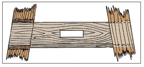
Figure 125—Bottom Rail of Work Bench
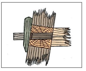
Figure 126—Joint between Rail and Bottom Stretcher
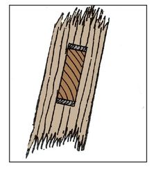
Figure 127—End of Rail in Leg
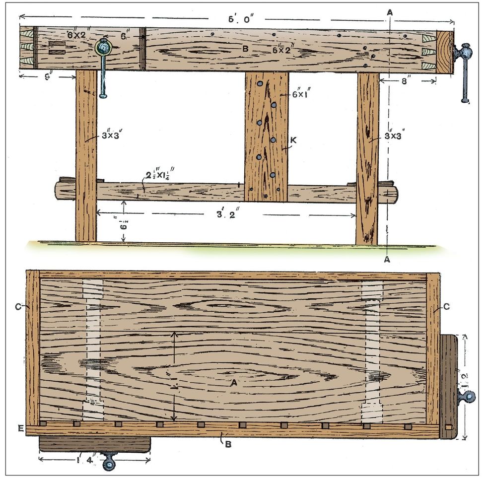
Figures 128 and Figures 129—Side Elevation and Plan of Bench with Side and Tail Vices
Bench with Side and Tail Vices
The general view of a bench with side and tail vices is given by Figure 61 and the construction of the bench is dealt with below. Figure 128 is a side elevation, Figure 129 a plan, and Figure 130 a section on A A (Figure 128). Having sawn out the pieces, next plan them true. Then set out the legs and rails, the latter for mortising, and the former for tenons. The mortises go right through, producing a much firmer result than when the tenons are only stubbed in halfway. The haunched mortise and tenons between the top rails and legs, with the tenons of the cross rails through the legs, are shown in Figure 131 and 132; the tenon of the rail is firmly held in position by a wedge, which must be released, and the tenon of the rail lifted up, before it can be withdrawn. The side rails have a bare-faced tenon—that is, have a shoulder on the inside only. When these joints fit suitably, the legs and cross rails should be glued together and cramped up, and the tenons fixed by wedges, which should be glued before insertion. The top should be planed to breadth and thickness, and then the ends cut off and planed square and to length. The front of the back and end cheeks c (Figure 129) should next be carefully set out and worked. At the front end of the side cheek B, the thickness for dovetailing is not the full 2 inches, but is less by ¾ inch than the breadth of the pin hole, as shown at E (Figure 129). After the side cheeks have been dovetailed and fitted together, groove the front cheek on the back for receiving the stop (see Figures 129 and 133). The inside edge of the top should be rebated as shown at F (Figure 130) to receive the well board. This should fit just tight between the end cheeks, the front and side back cheeks being firmly secured to the top plank and well board. Four-inch screws may be used for the front and side cheeks, and 2½-inch screws for the back, the heads being sunk a little below the surface. Glue the side cheeks to the main board of the top. Then mortise and tenor the cheeks and ends of the runners together as in Figure 134, the top of the runner being kept at the same distance from the top of the cheek as the thickness of the top plank; two tenons may be more troublesome to make, but the result will be stronger than when only one tenon is used. Make sure these joints are firmly glued and wedged together, with the runner at right angles to the cheek. In Figures 130 and 133 the construction of the guide boxes for the runners is clearly illustrated, the pieces G, a trifle deeper than the thickness of the runner, being firmly fastened to the top plank with 3½-inch screws. The bottom is formed of ¾ inch boarding screwed to the guides. The box for the tail runner extends from the top rail to the inner surface of the end cheek. You will find wrought-iron bench screws about 18 inches by ⅞ inch, having split collars, to be the most satisfactory, and in fixing them into their places, push in the cheek and runner so they are firmly held in position; then mark the center of the hole for the screw in the cheek, leaving sufficient room for the flange of the box (or nut) for screwing to the side cheek of the bench (see Figure 133). The hole should next be bored through the cheeks of the screw and bench with a bit slightly larger than the diameter of the screw. Then the collars and boxes can be fixed in position, and the framework of the legs and top fitted together. Notch the top rail of the back legs for the runner, shown by H (Figure 131), and if the work has been done accurately the top will just slide on the upper part of the legs. When the parts are adjusted, the front cheek should be secured to the legs, and the top of the bench to the top rails of the legs with 3½-inch screws. The peg board K (Figure 128) should be screwed to the front of the bottom rail and to the back of the front cheek. The following are the net sizes of the pieces required (a little in excess of these dimensions should be allowed for waste in working): Top board, 2 inches by 13¼ inches by 4 feet, 8 inches; well board, ¾ inches by 8 inches by 4 feet, 8 inches; peg board, ⅞ inch by 6 inches by 1 foot, 9 inches ; runners, 2 inches by 2½ inches by 2 feet, 3 inches; runner guides, 1½ inches by 2 inches by 3 feet, 2 inches; guide box bottoms, ¾ inch by 5½ inches by 1 foot, 7 inches; screw cheeks, 2½ inches by 6 inches by 2 feet, 7 inches; front and end cheek, 2 inches by 6 inches by 9 feet; back cheek, 1 inch by 6 inches by 5 feet; legs, 3 inches by 3 inches by 9 feet, 8 inches; top rail (front end), 2 inches by 4 inches by 1 foot, 9 inches; bottom rails (ends), 2 inches by 2 inches by 3 feet, 6 inches ; and bottom rails (front and back), 1¼ inches by 2½ inches by 8 feet, 2 inches.
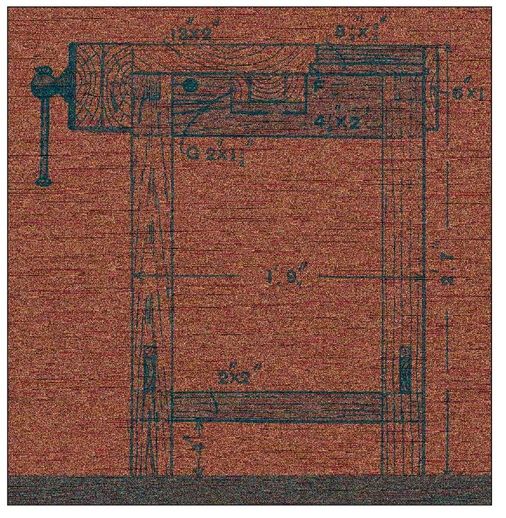
Figure 130—Part elevation and cross Section of Bench
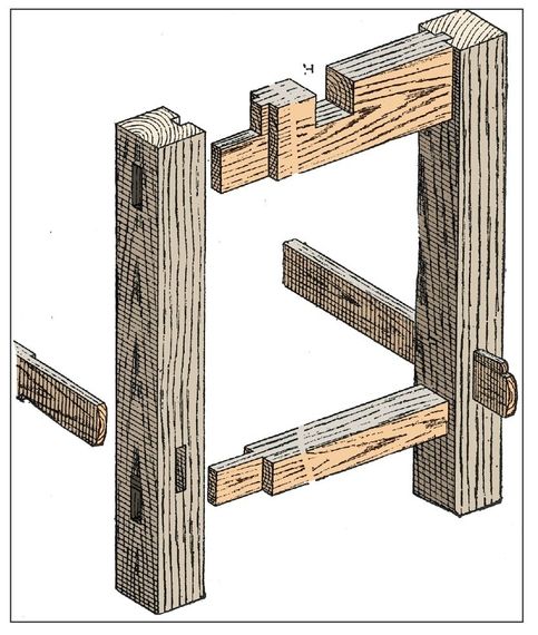
Figure 131—Joints of Rails and Legs of Bench
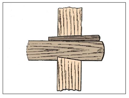
Figure 132—Section showing Rail wedged in Bench Leg
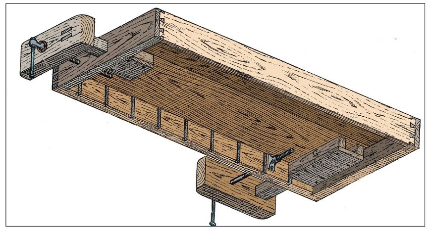
Figure 133—Underneath View of Bench Top
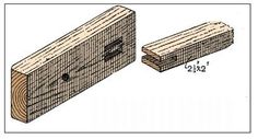
Figure 134—Bench Vice Cheek and End of Runner
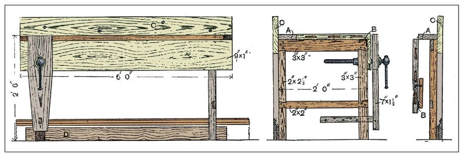
Figures 135 and Figures 136—Elevations of Folding Bench Figure 137—Folding Bench with Flap Down
Portable Folding Bench
The portable folding bench shown ready for use by Figure 63, and with the flap down by Figure 64 is illustrated in side elevation by Figure 135, and in end elevation by Figure 136. An end elevation of the bench when folded is given by Figure 137. Sizes that will meet all ordinary requirements are indicated in the illustrations, which show the construction so clearly that only the leading points need description. The legs and rails are jointed together by plain halving and dovetail-halving. The top is at least 1½ inches thick, and is formed of two boards jointed; to keep it true it should be clamped. The top should be hinged to the rail marked A, and the side of the bench hinged to the top as represented by B (Figures 136 and 137), 3-inch butt hinges being used for this purpose. The wall-piece c should be firmly screwed to the rail of the top A. The legs should be hinged at the top of this piece, and also at the bottom to the strop marked D, which should be sufficiently thick to project from the wall to the thickness of the wall-piece c. The piece c can be attached to the skirting board with a few screws. The wall-piece c, if against a lath-and-plaster partition, can be firmly and easily fixed to two or three of the studs of the partition with half a dozen screws; if it is against a brick wall, drill a few holes into the wall and drive in hardwood plugs; or, better still, probe the wall with a long fine bradawl until the joints are found (if this is done carefully, little damage will be suffered by the paper), and then with a steel chisel cut some holes about ¾ inch square and about 3 inches or 4 inches deep. These holes may then be fitted with hardwood plugs, into which screws are inserted through the wall-piece. The fitting-up of the screw, cheek, and runner (the last named being of hardwood) is not difficult. The leg to which the screw is attached is larger than the others. The side and top of the bench when folded up can be kept in position by a hook and eye as shown. The bench may be made additionally firm by inserting a few screws through the side into the legs, and through the top into the rails. When it is required to remove the bench, all that is necessary is to withdraw these screws.
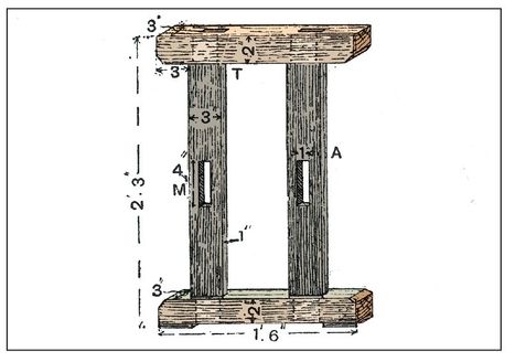
Figure 138—End Framework of Cabinet-worker’s Bench
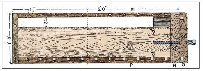
Figure 139—Top of Cabinet-Worker’s Bench
THE JUNIOR HOMESTEADER
Make a Birdhouse!
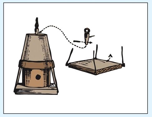
Teach kids basic woodworking skills with simple, fun projects. This is a small birdhouse that will hang from a tree branch. It’s perfect for wrens.
Materials
- Large tin can
- Wooden board about 7 inches square
- Carpet or upholstery tacks
- Earthen flowerpot
- Small cork to plug up the flowerpot hole
- Eye screw
- Short stick
- Wire
- Small nails
Directions
- Mark the doorway on the side of the can and cut the opening with a can opener.
- Fasten the can to the square baseboard (A) by driving large carpet tacks through the bottom of the can into the board.
- Invert the flowerpot to make the roof. Plug up the drain hole to make the house waterproof (use a cork or other means of stopping up the hole) (B).
- Screw the eye screw into the top of the plug to attach the suspending wire. Drill a small hole through the lower end of the plug so that a short nail can be pushed through after the plug has been inserted to keep it from coming out.
- Fasten the flowerpot over the can with wire, passing the loop of wire entirely around the pot and then running short wires from this wire down to small nails driven into the four corners of the base (A).
- Now the bird temple can be painted and hung on a tree.
Sawing Stools and Workshop Trestles
The joint most generally used for connecting the legs of the sawing stool to the top beam is shown in Figure 140. These joints may be fastened with nails, but a stronger method is to glue and screw them together. A serviceable trestle for workshop and general use is shown in Figure 141. Quartering of light or heavy scantling will be appropriate, based on the purpose you are using the trestle, and the method of framing it together will change as well. It is mortised and tenoned as follows. The four legs A are mortised into the top B, as shown in Figures 142 and 143. The mortise in B is cut longer than the width of the tenon of A, to allow for driving in wedges c. The complete joint is dovetailed, wider at the top than the bottom, and the legs cannot fall out. Drive in the wedges as shown, against the ends of the tenon and the end grain of the top B, and not against the flanks b of the tenons. If they were driven against the flanks b, they would split the top B. The short stretchers D (Figure 141) are mortised into the legs a, and wedges are driven in against the end grain, as in the previous instance. The long stretcher E (Figure 141) between the short ones is mortised in the same fashion. A trestle made thus with close joints will stand much rough usage. If the legs were short and the scantling of large section, as with a sawing stool, strutting would not really be necessary. But it is better to strutt high trestles made of slight scantling, say not exceeding 2 inches by 2 inches, or 2 inches by 2½ inches cross section. In Figure 141 the struts at FF are tenoned into b and e, but the tenons do not pass through, and are not wedged. It is quite enough to stump-tenon the ends of F F (Figure 144) at top and bottom. The two struts about at a, and further steady the framing. A simpler method of framing trestles of this type together is shown in Figure 145. The only members that are mortised are the legs A, into the top B. The cross stretchers c are simply let for about ½ inch into the legs, and screwed or bolted. The struts D are stump-tenoned into the top, but at the other end they are merely shouldered back to fit over the stretchers c (see also Figure 146), and screwed or bolted. For a somewhat heavy trestle this simpler method is quite good enough; but for a lighter trestle, like previously described, the method of framing together with long bottom stretchers and mortised joints throughout makes a firmer job.
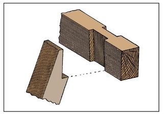
Figure 140—Joint for Sawing Stool
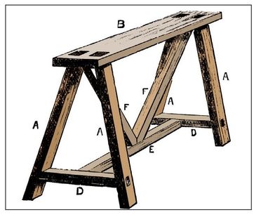
Figure 141—Workshop Trestles
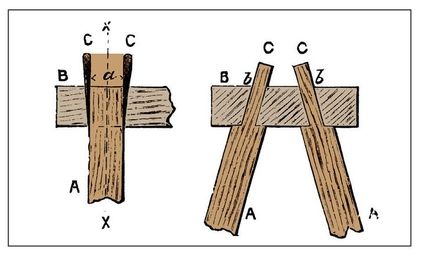
Figures 142 and Figures 143—Legs Mortised and Tenoned into Top of Trestle
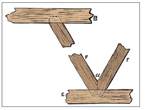
Figure 144—Struts Stump-tenoned into Stretcher
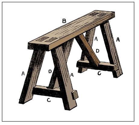
Figure 145—Workshop Trestle
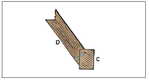
Figure 146—Strut Shouldered upon Stretcher
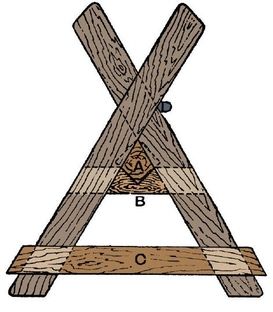
Figure 147—Sawing Horse
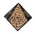
Figure 148—End of Longitudinal Rail of Sawing Horse
Sawing Horse
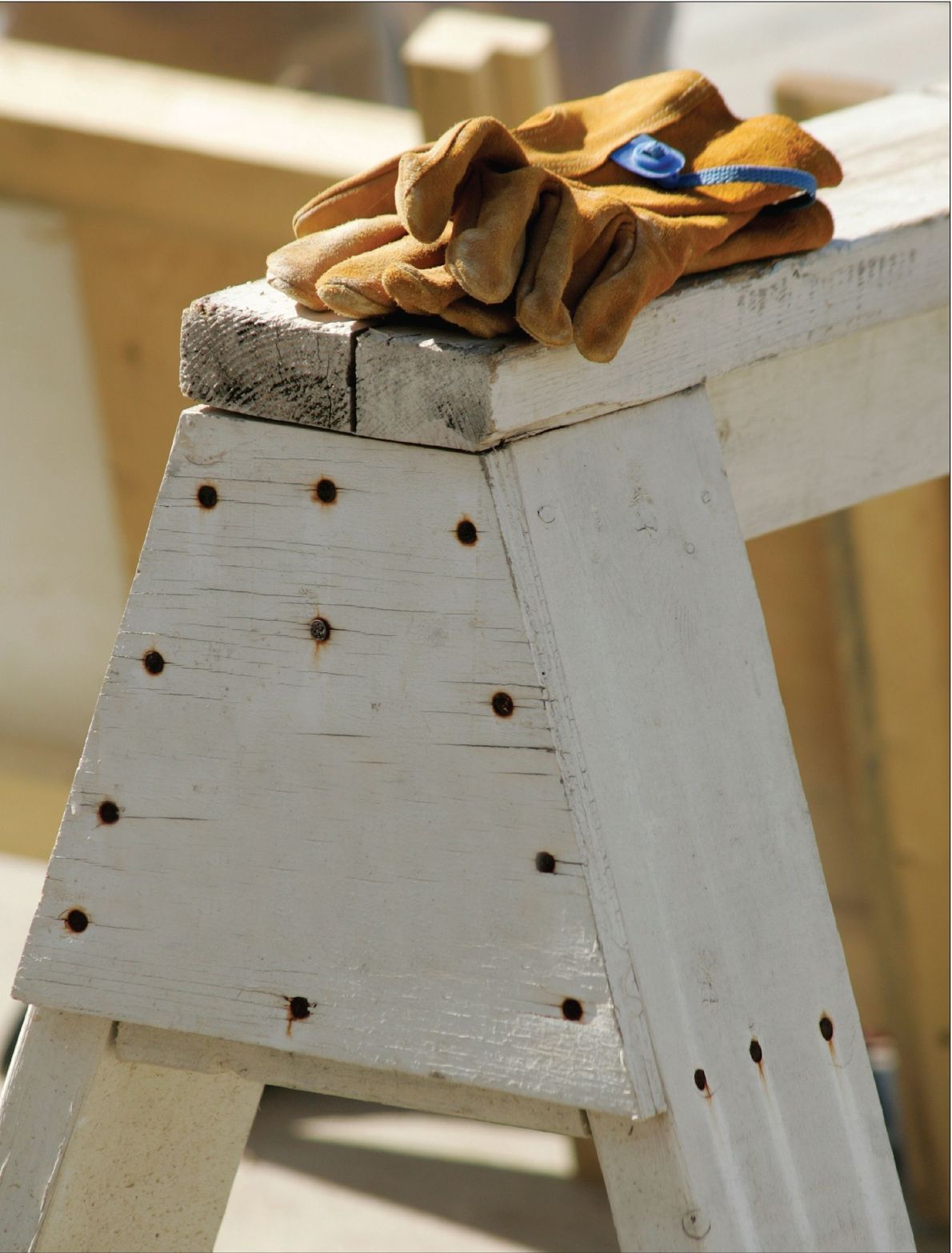
For sawing wood, and more especially for sawing firewood, a horse is a great help. There are more ways than one of making it; but this is best for ordinary use. This is mainly built of scantling 3 inches square, and is neat, strong, firm, and serviceable. The four pieces forming the legs are about 2½ feet long, and they are so arranged that the upper limbs of the cross have only half the length of the lower ones; They are halved at the intersection, and strongly nailed together, the nails being driven from the outer side and sent well home; for, should they project, they would be likely to catch and blunt the teeth of the saw. All the parts have to be so arranged as to leave nothing which can interfere with the free play of the saw, especially no iron. For this reason the central piece A, which chiefly serves to tie the two pairs of legs together, is kept below the intersections, so that it may fit up closely between the legs. Its two ends are, for a length of 3 inches, cut as shown in section by Figure 148. This piece is of the same scantling as the legs to which it is nailed. For ordinary work, 18 inches will be a good length for it. The upper cross rails B B give support to this piece, and are, as is shown, cut away to receive its lower angle at each end. These are of 1-inch wood, 2½ inches wide, and about 1 foot long, and are nailed to the inner sides of the legs. A part only of one of these rails is seen in Figure 147, but you can see its extent by the dotted lines. Now nail on the foot-rails c c, 1 inch by 2½ inches to the legs 2 inches from their bottoms. The cross foot-rails are 2 feet long, and those that run lengthwise 20 inches long. Keep the foot-rails as near the ground as indicated, so that your foot can rest comfortably on it when using the saw horse; some part of your weight being thrown on the frame will steady it.
Portable Sawing Horses
A better portable horse for general purposes than the one just mentioned can hardly be desired. If less solid, it would be lacking in firmness, and if too strong, it would be liable to be shaken to pieces by the constant jarring to which it is subjected in use. But sometimes a lighter and more portable horse is desired, and to meet this requirement a shut-up horse may be made as follows: After halving the two pairs of legs as above, cut mortises through them at the intersections, say 1 inches wide by 1½ inches beyond them. In each tenon will be a hole into which a pin, removable at pleasure, can be driven to fasten the frame together for use. In convenience and stability this horse is of course greatly inferior to that described before.
Fixel Sawing Horse
The most simple as well as the firmest of all sawing horses is, however, the primitive fixed one. The legs of this should be about 1 foot or 15 inches longer than those shown in Figure 147, and, pointed at the ends like stakes, they are driven into the ground before being nailed together at their intersections. To connect the pairs, all that is needed is a tie nailed to the legs at the point D (Figure 147), that is, just below the upper limb and on the side upon which the sawyer will stand. Such a horse has the merit of complete immobility; but, of course, it will not serve every purpose.