Architects should be wary of those who exaggerate the impact of passive solar design. We often hear presentations that aggressively tout the energy savings of passive solar design strategies—though without understanding the specific context, climate, building type, and other details, these statements can be misleading. Additionally, after years of simulating almost any design feature we could think of, we have discovered that there is no single catch-all design strategy that will save massive amounts of energy. Instead, saving energy involves the craft and artful combination of as many design and material strategies as the project can hold—in other words, the synthesis of multiple measures into a whole. The modern monikers of less is more or form follows function do not necessarily suit what the modern masters intended, given the growth of heating, cooling, electrical, and water systems in buildings. With all of this new technology, buildings today are anything but less.
Passive solar design is the use of architecture and climate to provide heating, cooling, and ventilation without mechanical (active) systems. Another way of describing passive solar design is the use of free resources provided by the sun, wind, and earth. Without the intent to design the architecture to integrate and embrace these free resources (a technique known as bioclimatic design), the building must rely on active mechanical systems to provide the heating, cooling, and ventilation. Formulating the architectural response to climate often begins with geometric design considerations.
Form does not follow function—instead, the form of a climate-adapted building is a function of energy performance, known as performance-based design. Here, form follows performance. How so?
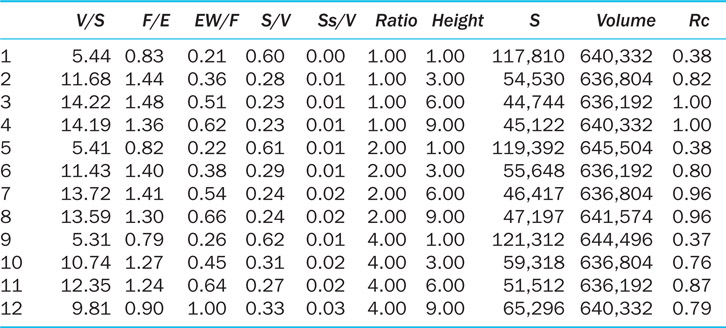
Orientation (Figure 6.1) has long been a primary passive solar design strategy, and ranks among the most researched; however, it is not as sensitive as building geometry, such as the building’s aspect ratio or height (what we call stacking). Aspect ratio (Figure 6.2) is the two-dimensional relationship between a building’s length and width, while stacking (Figure 6.3) is a building’s vertical proportion and the number of floors, which increases as the building grows in height. These are the three main building blocks that architects use to design a building’s form and delineate its two- and three-dimensional envelope shape.

Figure 6.1
Orientation diagram showing the optimal east to west degree rotation for climate zone 5 to maximize southern exposure and minimize western solar radiation.
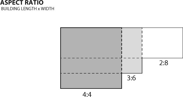
Figure 6.2
Aspect ratio showing the relationship between a building’s length and width while maintaining total floor area.
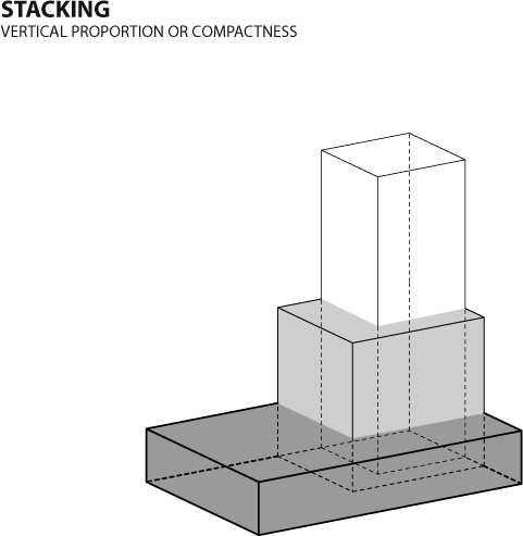
Figure 6.3 Stacking diagram of a building’s vertical proportion maintaining internal volume.
Geometric properties are sensitive not only individually, but when evaluated together. Combining orientation, aspect ratio, and stacking defines the shape effect. Proper orientation should go hand in hand with both aspect ratio and stacking. Buildings take on many different shapes, and evaluating their effect on energy use is a study more complicated than merely evaluating a single geometric principle.
Some common building geometries include the letter shapes L, T, H, U, and others. As explained by Thomas Hootman, “the creation of narrow shaped floor plates with fingered wings and courtyard spaces allows for daylight and natural ventilation,”2 and such floor plates are ideal for passive solar design. Looking at the architectural composition of a building form based on these simple shapes is one way to begin.
Combining the metrics of aspect ratio and stacking for a fixed square footage and floor-to-floor height results in an array of different building forms, as seen in Figure 6.4. These forms represent different potential designs, and depending on your climate and use type, the energy performance of these building geometries will vary widely.
Another geometric design method is shape aggregation—piecing together similar or dissimilar shapes into a massing. As the name implies, one can imagine shape aggregation as the architect putting different types of blocks together to compose the building’s overall geometry. While shape effect looks at one mass, a building’s massing is the assimilation of many forms, whether similar or different (Figure 6.5). Evaluating a building’s massing is often necessary in larger

Figure 6.4 Conceptual massing of 12 different combinations of aspect ratio and stacking.
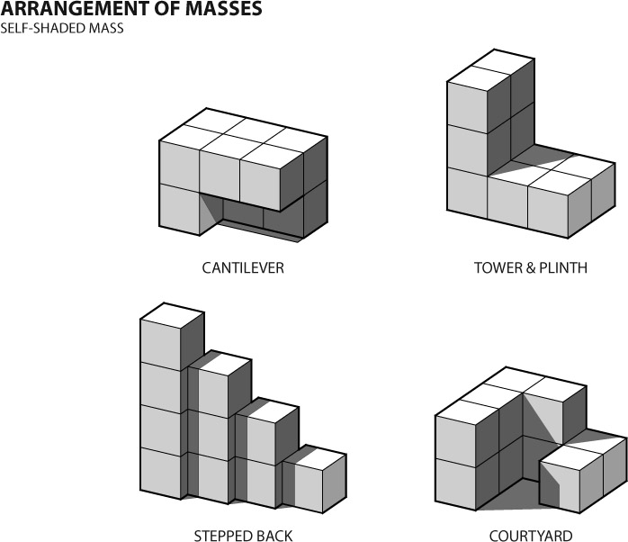
Figure 6.5
Examples of shape aggregation or massing of a building’s form.
buildings, complexes, and campuses—for example, in a hospital, or in part of an addition to an existing building.
The composite mass affects the building’s energy use either by shading some parts or by maximizing solar access in other parts. The two approaches of shape and mass influence other design decisions, such as the location of glazing or the fenestration design. Climate-adaptable strategies explore the relationship between the building’s overall mass and the sun (often referred to as the solar envelope3). This relationship has been the subject of much research and has influenced both policies in certain areas and the design of entire cities, such as the planned Masdar city project in Abu Dhabi. In colder climates, shaping the solar envelope and building mass allows sunlight penetration and maximizes the uptake of the sun’s radiation for heating. Alternatively, as in Masdar, hot climates lead to a shape and massing of buildings and urban forms that reduce the sun’s penetration, helping to cool the city’s narrow streets.
While the early design of a building remains fluid as the building evolves through the various stages of design understanding, its geometric sensitivity to energy use is critical. As discussed, there are ranges of geometric issues that affect how a building form works as a function of energy. The orientation, aspect ratio, stacking, shape effect, mass, and scale of the building’s geometry all play into a complex orchestration of energy use. During discrete analysis with BEM, these individual elements interact in complex, formal relationships that affect energy use.
There are several metrics used to measure a building’s geometric form and relate it to energy performance. Research shows that geometry-based indices only correlate with a building’s thermal performance according to specific climate regions and building types;4 therefore, it is paramount to evaluate energy use with BEM during design to evaluate how modifications to a building’s geometry can affect its energy use. The geometric measures below are helpful in making case-by-case comparisons between different iterations of a building design; however, when comparing different building types and climates, you likely are comparing rocks with apples. Following this summary is the literature review discussing the research.
- Compactness index (C) is a measure of the building’s internal volume-to-exterior surface area (V/S), with the higher number being the most compact. It is the inverse of the shape coefficient.
- Shape coefficient (Cf) is the ratio of surface area to volume (S/V), where (S) is the sum of all surface areas in contact with the outside air and the building’s enclosed internal volume (V).
- Relative compactness (RC) is the ratio of a building’s compactness index (Ci) to the compactness index of a reference building, with the reference building being the more compact.
- Window-to-wall ratio (WWR).
- Window-to-floor ratio (WFR).
- Window-to-surface ratio (WSR).
- Floor area to enclosure (F/E).
- Exterior wall to floor area (EW/F).
- South exposure coefficient (Cs) is the southern-facing wall-to-volume ratio (Ss/V).
- Shape factor or aspect ratio (AR) is the ratio of the building’s length to depth.
- Above-grade surface area (S) is the surface area of the building, walls, and roof.
- Building internal volume (V) is the building volume enclosed by the ground floor, walls, and roof.
The above metrics typically quantify building geometry and come from a wide range of literature. The most common metric is building compactness. Compactness is the building’s volume divided by its exterior surface area (V/S).5 While early building literature considers S to include the exterior area in contact with the ground, more recent discussions omit this from the value of S, limiting it to only the above-ground exterior surface area. This measurement is not necessarily an absolute, but you should define it for your project. If you have a large amount of below-ground building area, you can either quantify this area as part of S or break the surface area into two different values for that above ground and that below, we suggest Sa and Sb.
The inverse of compactness is shape coefficient describing the total building’s surface area over the building’s overall volume (S/V).6 When evaluating a building’s geometry using these metrics, it is common to keep the volume constant: A 3,000 m3 building’s energy use is very different than that of a 300,000 m3 one, though they may have the same compactness. For instance, in Figure 6.6, where the building surface area is minimal, the stacking of a building that maintains its volume is most compact at the mid-range.
Another version of the shape coefficient as proposed by Jon Straube also eliminates the ground-floor area from compactness, suggesting that floor area/ enclosure (F/E) is more accurate than the compactness proposed by Gratia and Herde. This not only makes logical sense, it is consistent with the research and a building’s differing thermal performance with the ground versus through its walls or roof. Straube also eliminates the total interior volume from his considerations and prioritizes only the floor area, arguing that in most buildings the interior volume value is misleading due to the size of the plenum spaces that alter the interior conditioned space volume.7 Adding to these metrics, Thomas Hootman, in his
book Zero Energy Commercial Buildings, suggests that the total exterior wall area divided by the floor area (EW/F) is ideal for measuring a building’s passive solar design potential8 while also using the shape coefficient (S/V), the inverse of the compactness index.
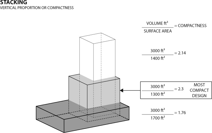
Figure 6.6 Example of how stacking affects a building’s compactness index, showing the most compact form versus two other options.
To summarize the building volume-based measures, you have compactness as the volume/surface area of building (V/S), the floor area/ enclosure (F/E), the exposed wall/floor area (EW/F), and the surface area/ volume (S/V), all of which highlight different geometric volumetric measurements of various building forms. Other two-dimensional and related metrics include the building’s quantifying shape factor/aspect ratio (the building’s ratio of length to depth, L/D), along with the building’s overall height (H), surface area (S), and volume (V).
Finally, research by Eugénio Rodrigues quantifies a clear and comprehensive list of variables, called geometric indices,9 which includes those highlighted above and the WWR, which is usually the percentage of glazing compared with the total wall area. Additionally, the WFR is familiar to architects primarily because building codes require a minimal amount of windows compared with the floor area for natural lighting and ventilation. Other ratios on the geometric indices list are the WSR and the southern exposure coefficient (Cs), which relate exclusively to different ways of measuring the surface of the building itself. To compare the building’s energy use with its geometry, it may be helpful to utilize these measurements depending on what questions you need answered. Table 6.7 summarizes the geometric indices shown for the conceptual masses in Figure 6.4.
This summary of building research studies and geometric indices allows one to correlate a building’s thermal performance (its energy use) with the geometric building metrics. Architects examining different climate zones and building
shapes can benefit from understanding which specific measurement might work for the building type in the specific climate. For robust analysis results, simulations of hundreds of different building shapes are necessary, though not everyone has time to find the correlation between geometry and energy use within a particular climate. There are enough differences in each particular building’s type, program composition, and system that no one element can serve as a catch-all for a designer to specifically focus on; designers should instead seek balance between the most crucial elements for that particular building’s needs.
Which particular piece or pieces do you emphasize to achieve the desired effect? With BEM, architects can test and evaluate iteratively to create a clearer design decision. Our experience is that most often a particular solution is not optimizable (if we may use such a word), meaning there is not necessarily a perfect answer to a problem. Historically, this large solution space for building design has been a challenge. Fortunately, our computational tools today open new doors and opportunities to search this space for an approximate answer that might work.
Geometry across Climates and Building Types
Geometric sensitivity of a building’s form varies due to many complicating factors, primarily climate and building type. A specific geometry that might work for a building in Boise, Idaho is not going to perform the same in Athens, Georgia. An evaluation of the climate and passive solar opportunities is critical to reduce energy use when beginning a design in any location. Refer to Chapter 3 for weather data and climate analysis tools for BEM.
As briefly identified above, the geometric measures of a building’s form can help in understanding its energy use using BEM. For instance, in colder climates a building’s compactness typically relates to the amount of energy required to heat it. A higher compactness number exposes less surface area to the environment, making the building more efficient to heat. However, a compact building form would have a lower exterior wall to floor ratio or southern exposure coefficient and these are often useful metrics to maximize passive solar heating or daylighting. Therefore, searching for an optimal number in one measure of a building’s geometry may exclude the opportunities afforded by others. Balancing discrete with whole-building decisions with your energy goals can overcome this.
A compact building form often helps in cold climates, whereas a less compact building form may help in hot or humid climates. For example, a less compact form (Figure 6.4) has more roof area, decreasing the total envelope’s U-factor and increasing the amount of floor coupled to the earth. In a hot climate, this is likely to decrease the building’s cooling needs. Shape-based indices such as compactness often demonstrate a strong (or sometimes very strong) negative correlation,10 meaning that the difference between being less compact and more compact does indeed affect the building’s energy use; however, it might not always be affected in the way you predict. For example, if we maintain a building’s shape coefficient and make the building taller, the building becomes less compact since we have more wall area and have shrunk the roof by adding more floors within the same volume; this will also increase the EW/F number. Therefore, within an internal-load-dominated building type, such as a large office, this may actually help reduce cooling, since we are increasing the amount of wall area. Another benefit of more wall area is that there are greater opportunities for daylighting the building, further reducing its energy use by moving the loads from internally dominated to more skin dominated.
When considering a building’s windows and glazing properties, the common advice is to reduce the amount of glazing on its east and west façades. On these exposures, the sun is far more difficult to control due to its low position in the sky as it rises and sets over the course of a day. Evaluating the various window metrics may yield some help in balancing the thermal loads for a specific climate. Research on the window-based index shows a moderately negative correlation in cold climates for two- and three-level design programs;11 therefore, in a cold climate, increasing the amount of glass decreases energy use. How so? In residential buildings, increasing the amount of glass will often increase the amount of passive solar heating. Regardless of the geometric indices chosen, however, careful consideration of the thermodynamic relationship of climate and building type will help designers make decisions and build on their BEM.
In addition and in response to climate, design decisions related to other building factors such as site selection, program, space layout, window location and size, fenestration design, and material choice can all be evaluated early in and throughout design using BEM. Do not evaluate all of these factors at once! When starting a BEM baseline as discussed in Chapter 5, the following iterative design process builds on the BEM and helps define with more certainty the design priority for your specific building within the design process. An experienced project architect or manager may identify and prioritize design issues more easily than others. In the absence of a manager’s expertise, the design process the book adopts follows MacLeamy’s optimal design process curve. By using the curve, a designer using BEM to evaluate key points during design knows when these decisions may occur.
Following the BEM framework, the modeler can evaluate other building factors. Where you might choose to begin is dependent on circumstances and issues specific to the project. Based on the authors’ experience and from a review of literature written about BEM in design, the subsequent paragraphs highlight how and when to use BEM during design to assess a building’s energy use related to site, program, space layout, WWR, fenestration design, and material choices.
Site Considerations
Site evaluations using BEM will depend in large part on how accurately your model represents the building’s context, whether it be rural, suburban, or urban. BEM tools are not well-suited for modeling topography or vegetation due to the geometric complexity of these elements, meaning that exploring alternative methods is necessary for these features. However, in understanding the impact of existing buildings on a particular site, there are numerous opportunities for using BEM. Based on the surrounding buildings and the project location, radiation, shadows, and wind flows are factors in urban areas.
Evaluating one such factor is the relationship between differing formal urban morphologies and solar radiation. Ralph Knowles at USC developed the concept of the solar envelope, explaining how architects can design a building within the urban form to maximize or minimize daylighting within the surrounding environment.12 Similarly, the solar envelope also could articulate the solar radiation levels within the urban form as a way to select sites or understand the energy impact of urban design decisions. Designers may choose to avoid or embrace aspects of an urban context depending on the type of project. MIT has an urban-modeling plug-in for use in Rhinoceros that explores many energy-related issues of urban design.13 From MIT and the creators of the BEM tool DIVA, the UMI plug-in allows the testing of different urban form issues.
In any context, understanding the possibilities of different suburban or rural site exposures for sun or wind access is also important when siting and designing bioclimatic buildings. The landform affects how the wind moves and how you choose to shape your building for natural ventilation. In the Hawaii preparatory academy case study discussed in Chapter 8, once the CFD modeling of natural ventilation was complete, design revisions were made to improve the building’s passive cooling. In addition, the energy modeling consultants analyzed the larger landform to model wind direction.
Program and Use
Essentially, people give off heat, and our activities while in a building cause our heat levels to fluctuate. Our specific habitation of a building contributes to the internal heat gains and determines the amount of heating and cooling needed. Understanding the type of program and its associated uses allows an estimation of the occupancy heat gain. The age, sex, and other factors of the occupants help to define the amount of heat and moisture (latent heat) we contribute to the internal environment. Occupant density is the number of people in a space determined by the occupancy type and allowable density per code requirements. For instance, our sitting at tables in a restaurant results in a lower overall density (0.7 people/100 ft2)
than an auditorium (12.5 people/100 ft2),14 where people sit closely together in many rows of seats. Compare these with a gymnasium (3 people/100 ft2), where people are not packed as densely as in the auditorium since they are sweating and far more active. These factors influence the amount of sensible and latent heat we contribute to the interior of the space. Sensible heat raises the air temperature, while latent heat contributes water vapor to the air. Their combination determines the total heat gain from occupancy.
Following the occupancy from use and program types is the contribution of electric lighting to the internal heat gain. Lights generate heat as a byproduct of the illumination they provide. The type of light, its illumination level, and its efficiency determine the amount of heat it will produce. The illumination level necessary depends on the type of activity. Specific visual tasks—for instance, drafting on a sheet of paper—will require higher levels of illumination. Illumination is the amount of visible light we see on a surface, measured in foot-candles or lux. While drafting requires higher illuminance levels (50–100 foot-candles), general work environments may only require 20–30 foot-candles on the work surface.
Lighting, plug and process loads, and occupancy comprise the properties for the thermal zones of a layout. These dynamic, non-design-dependent features of program and use determine the LPD, plug loads, and occupancy load settings used in a BEM. Depending on the type of BEM tool used, for the whole building these factors are applied as a single zone or input into each zone of use. Modifying the LPD, plug loads, or occupancy in a BEM can affect both the building’s electrical use and its heating and cooling loads.
Program Examples
Investigating a variety of program mixes in a building is useful in understanding how different use types perform. For instance, the example in Figure 6.9 compares the mixed residential and commercial uses in a common building in terms of their contribution to total energy use. Since the energy footprint of commercial buildings
is typically larger than that of residential ones, the mixture of the two changes in a non-linear manner. Depending on the project goals, program analysis can assist the design team in deciding the right mixture of uses in a larger multi-use facility.
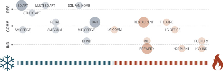
Figure 6.8 Diagram showing a range of building type uses based on internal heat loads. Iconography developed from icons found at https://thenounproject.com. Courtesy of Christopher Rokahr.
Another way to think about program mixing is to evaluate internal-load-versus external-load-dominated types. Comparing the dominating mode of operations for building programming can aid the design team in locating spaces or programs in the design accordingly, or in helping the owner identify ideal mixes of occupancies. Figure 6.8 maps out some common program spaces based on their internal heat production.
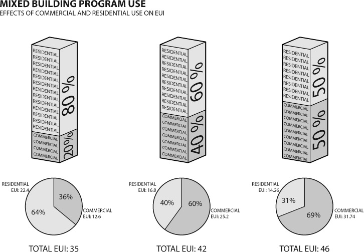
Figure 6.9
Diagram of programmatic mixes of residential and commercial and resulting energy usage intensity (EUI) of three combinations.
Finally, somewhere between these two examples is space-by-space energy mapping for large program types, such as healthcare facilities. Completing a
space-by-space analysis can help designers locate and distribute spaces or prioritize areas within the building that require more attention. Armed with energy-use information, owners can prioritize different types of services and understand the long-term impacts of high-energy-use areas versus low-energy-use spaces for inclusion in the building design.
These three examples highlight how, even during the pre-design stage of a building project, programming with BEM for different types, sizes, quantities, and adjacencies of spaces and energy considerations can be crucial in maximizing architecture’s ability to conserve energy.
Space Layout
Space use decisions made using BEM tools can help designers understand where to locate different rooms and spaces, a process referred to as daylight and thermal zoning, where spaces are located in the floorplan based on their daylighting needs or thermal performance. Many BEM tools can complete daylight analysis to show the quality and amount of daylight within a particular building space, while others can visualize the amount of solar radiation a site or building mass will receive, helping designers locate spaces based on thermal solar needs, or avoid other areas where intense radiation would cause the occupants to overheat.
The interior layout of a floorplan establishes how spaces relate to the amount of sun, light, heat, or cold gained. Layout matters when planning the interior of the building. Whether in space planning for daylight or thermal comfort, how the plan evolves is an essential part of passive design. Measuring space planning energy use is not a typical operation. Some BEM tools are set up for individual thermal zones based on the types of uses identified in the plan and the building’s particular thermal needs. However, when completing simulations earlier in design, less space information may be available, and the designer might not know the precise location of different functions within the building plan. Therefore, evaluating the floorplan with BEM early in the design process may not work well, but one can evaluate other important issues to space planning, such as daylight on a generic floor.
Daylighting is a driver of interior space layout—a process referred to as daylight zoning—in many high-performance buildings. Daylight zoning relies on locating spaces that are suited for natural light in the appropriate location. People want to work or live in daylight, and prefer these areas over those lit by electrical lighting. Running simulations to determine the quality and quantity of daylight helps design teams to allocate spaces according to their need for natural light. Two metrics used to identify daylight quality are spatial daylight autonomy (sDA) and annual sunlight exposure (ASE). sDA is a measure of the annual usable daylight in a space, while ASE is a measure of the space’s annual exposure to direct sun that can cause glare. Since the simple goal is to maximize sDA and minimize ASE, designing top- and side-lighting to achieve 100 percent sDA would mean
that the space is engulfed in daylight for all occupied hours over the course of the year. Alternatively, if you had a space that was 100 percent ASE, the space would be flooded with far too much light—great for a greenhouse, but not so much for other activities like working or reading comfortably.
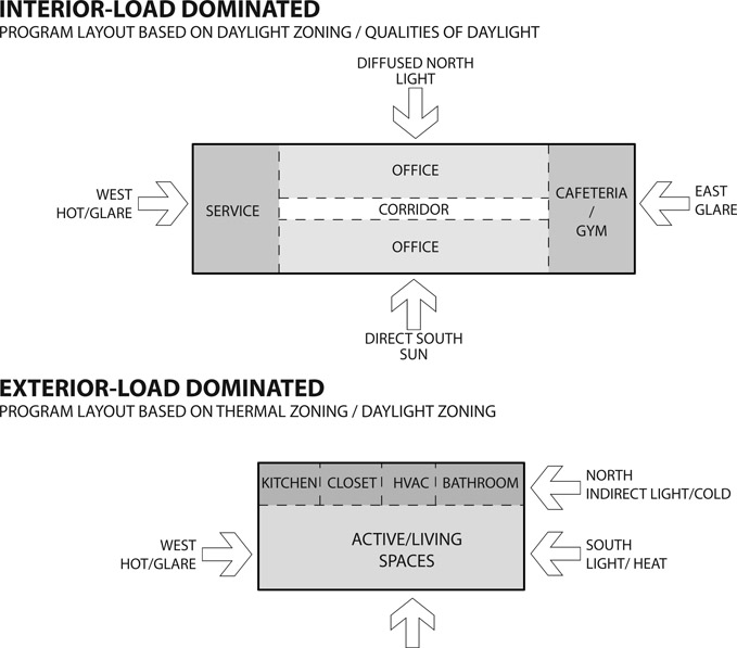
Figure 6.10 Common space layouts for internal-load- and external-load-dominated buildings, which prioritize thermal or daylight zoning.
Spatial layout of a building plan based on daylight zoning involves locating rooms and spaces based on the quality of daylight. The most common example is highlighted in Figure 6.10, where main workspaces are stretched along the south and north façades. Along the north façade, diffuse daylight will penetrate, and on the south façade—with proper fenestration—natural daylight can reduce the need for electric lighting. To elaborate more on spatial layout based on daylight, we will later discuss overall fenestration design.
Thermal zoning considers the location of spaces based on heating and cooling needs to take advantage of synergies. This is contextual; for instance, spaces that can be hot may be located near the west elevation, where it matters much less that they heat up during the day. Or spaces that may be colder may be located on the north side of a building, away from the heat of the sun. These ideas are nothing new to the design of architecture. Vitruvius, in his ten books on architecture, elaborates on how to lay out spaces based on the sun:
We shall next explain how the special purposes of different rooms require different exposures, suited to convenience and to the quarters of the sky. Winter dining rooms and bathrooms should have a southwestern exposure, for the reason that they need the evening light, and also because the setting sun, facing them in all its splendor but with abated heat, lends a gentler warmth to that quarter in the evening. Bedrooms and libraries ought to have eastern exposure, because their purposes require the morning light, and also because books in such libraries will not decay.
Dining rooms for Spring and Autumn to the east; for when the windows face that quarter, the sun, as he goes on his career from over against them to the west, leaves such rooms at the proper temperature at the time when it is customary to use them. Summer dining rooms to the north, because that quarter is not, like the others, burning with heat during the solstice, for the reasons that it is unexposed to the sun’s course, and hence it always keeps cool, and makes the use of the rooms both healthy and agreeable. Similarly with picture galleries, embroiderers’ work rooms, and painters’ studios, in order that the fixed light may permit the colours used in their work to last with qualities unchanged.15
The principles behind the logic expressed by Vitruvius involve designing around the sun’s seasonal differences. Since Vitruvius lived in Italy, his advice is only applicable for that specific location, but his ideas have inspired other architects throughout the centuries to design for their own bioclimatic locations.
Other strategies beyond the location of rooms are the creation of thermal buffer spaces, which help to mediate between internal and external thermal conditions. We are all familiar with some of these thermal buffer spaces in residential dwellings: crawl spaces, sunrooms, enclosed porches, and others. These spaces, designed and utilized correctly, can buffer the building from hot sun or extreme winter winds. In commercial buildings, a greater range of space complexity requires designers to consider an increased number of thermal needs. Depending on the type of commercial building, datacenters, server rooms, and commercial kitchens can all create more heat than they need. These spaces could be located on the perimeter, along the north or west, where the spaces can cool passively. Alternatively, in colder climates locating these spaces strategically could reduce the building’s overall heating needs.
A thermal storage space can store excess heat from higher thermal zones to use at different times of the day or night or in other areas of the building, essentially reusing the heat created by the building operation systems. Thermal storage spaces can also be used to help cool the building passively. Earth-coupled systems such as a labyrinth or earth tube can reduce the temperature of the air as it moves into the building.
To summarize, designing for thermal and daylight needs has long been important to architects over the centuries. Today, our advantage lies in our ability to simulate with a high degree of accuracy both the amount of available light within spaces and the thermal performance of spaces exposed to the sun. When used together, BEM and other simulation tools help to evaluate the complex aspects of daylighting and other design elements. BEM tools are only beginning to link the use of daylighting to a building’s energy performance, as we discuss further in Chapter 7.
Window–Wall Ratio
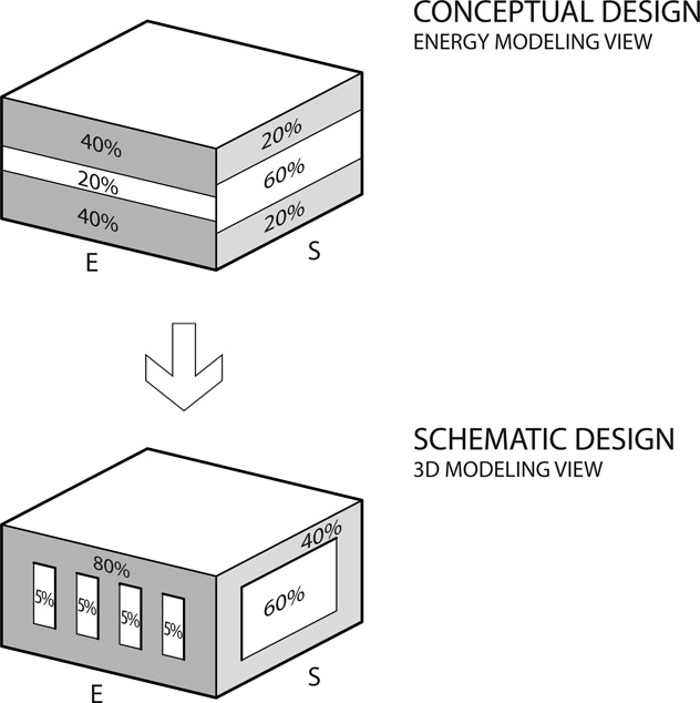
Figure 6.11
Common space Example of how WWR is defined for a building façade related to either the total wall area typical for WWR or as a percentage of the floor area (WFR).
When designing with BEM, one aspect to evaluate is the amount of glazing on a façade. In a typical BEM, the location of the glazing is not usually as critical as the amount of glazing the various building façades have. Early on in pre-design, this might not be as important as it is during the schematic design (SD) and design development (DD) phases following the definition of spaces, but what is important is evaluating WWR often as the design evolves: it is not necessarily something to analyze once and then set in stone. In addition to inextricably linking the quality and quantity of daylight, WWR (Figure 6.11) intimately relates interior space layout
and fenestration design. From our analysis, WWR is one of the most interconnected design elements; in other words, changes in other elements such as the walls or roof will have a large impact on how WWR behaves in relation to energy use.
The type of window, the frame material, and the glass used all affect the amount of solar gain, the sun’s affect on the building’s heating and cooling loads. Windows either allow sun to pass through or reflect the sun’s rays; this amount is a function of the solar heat gain coefficient (SHGC). SHGC is the glazing’s efficacy at blocking the sun and is expressed as a number from 0.1 to 1.0. Alongside SHGC is the amount of visible transmittance (VT), the amount of light that passes through the window. VT is not as significant a factor for energy use as SHGC, but considering VT is nonetheless an important qualitative design decision: Installing windows that people can’t see out of or that don’t let in light would defeat the purpose of having a window.
As an example of the SHGC glazing property, a change in SHGC creates an inverse relationship between the annual space heating and cooling loads. While this may appear to result in no real energy savings in certain climates and building types, in the case of our medium office building located in Miami, Florida, the lower the SHGC, the greater the annual energy use, as Figure 6.12 shows.
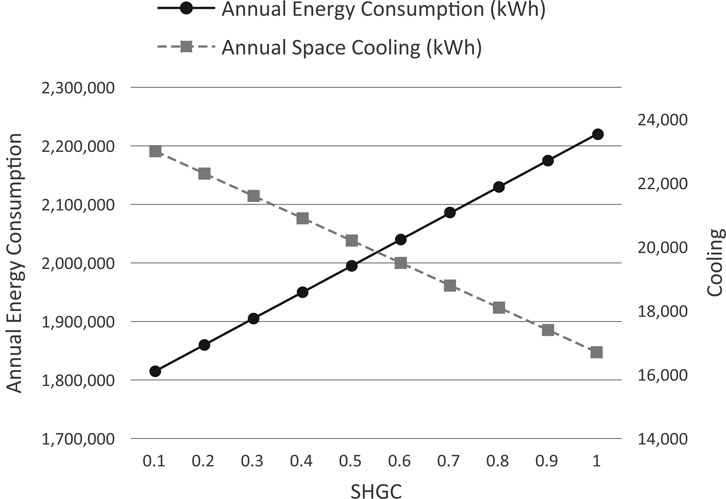
Figure 6.12
Example of SHGC effect on a large office in Miami, Florida showing annual cooling loads (right axis) and annual energy consumption (left axis).
In the case of passive solar heating in a colder climate, a lower SHGC decreases the amount of passive solar heat gain that reaches the interior. The same simulation in a different climate results in the graph shown in Figure 6.13. Here, the annual energy consumption is not linear, suggesting an optimal SHGC of 0.4. Similar to the Miami building, the heating and cooling loads have an
inverse relationship, though the effect of passive gains through the windows allows us to make a clearer decision regarding the SHGC value for the windows in this colder climate.
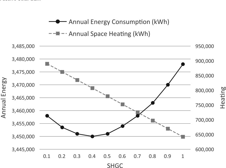
Figure 6.13 Example of SHGC effect on a large office in Burlington, Vermont showing the annual energy consumption (left axis) versus annual space heating (right axis).
Determining the proper WWR requires that the building architecture and engineering leverage the distribution of glazing and how it is used for lighting, heating, cooling, and ventilation. The general approach is to maximize glazing for daylighting and minimize the glazing for overheating. While this seems like a relatively simple concept, it is actually quite complex. As one increases the glazing to maximize daylight, one is also increasing the amount of heat gained and lost (depending on your climate) through the building envelope. This is because a window is the least thermally efficient element of the building envelope. The other complicating factor is that more glazing introduces more glare into a space, which reduces the overall quality of the specific area.
Solutions to address these complexities involve the strategic use of shading devices both internally and externally, the planned distribution of spaces, and the careful design of the window locations and building form.
Fenestration
The design of fenestration is the thoughtful integration of the windows, both the glass and frame materials, with the building’s interior walls and shading devices. There is a seemingly endless variety of combinations of different windows, materials, and possibilities for resolving a building’s fenestration; one could locate interior blinds, roller shades, or drapes to coincide with various exterior blinds, awnings, and overhangs. Devices that are vertical, horizontal, or fixed versus adjustable could be combined into eggcrate-type shades or a specific sun-screen. The overall goal of these combinations is to address the lighting, heating, and cooling issues faced by different building types in different climates (Figure 6.14).
Next, to demonstrate several of these complexities, we simulate a series of fixed exterior shading device types to investigate the effect these systems have on reducing a building’s energy use, doing so alongside the daylight performance (Figure 6.24). The common shading devices are vertical, horizontal, egg-crate, and perforated skins, as shown in Table 6.15 and Figure 6.16.
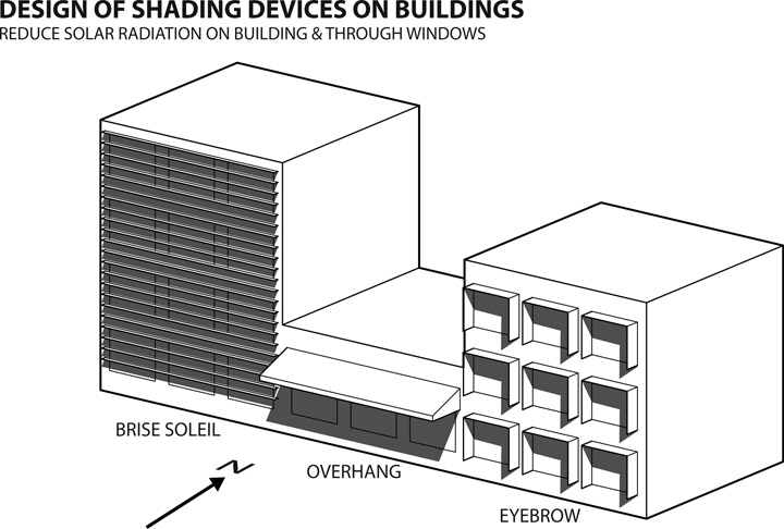
Figure 6.14
Basic types of fixed building shading devices used to reduce the solar gains through windows and solar irradiation on building surfaces.
Table 6.15
Common shading devices evaluated, shown in Figure 6.16.
|
Vertical shading
|
Vertical twist
|
|
|
|
Horizontal shades
|
Horizontal overhang |
|
Brise soleil |
|
Egg-crate
|
Diagonal lattice |
|
Panel eyebrow |
|
Cone panel |
|
Perforated skin
|
Circle packing |
|
Checkerboard |
Certain types of buildings with large internal loads should avoid unwanted heat gain from the sun. An ideal strategy is the use of shading devices on windows that still allow daylight and pleasing views. For example, if used in Miami, the brise soleil can shave three percent off the annual energy consumption of the building previously modeled above. The awning, however, is not nearly as effective, and
only reduces the annual energy consumption by one percent. Therefore, for the large office building in Miami, designing fenestration to include a brise soleil on the exterior would be worth further evaluation.
Figure 6.16 Variety of fixed shading devices evaluated with BEM in the design examples.
Materiality of the Building Envelope
Materials are another important consideration within the BEM. Material choices we make during design do not often affect the building’s overall form or design. One of the most common material properties modified to affect the building’s performance is a material’s thermal conductance, commonly known as its U-factor. Thermal conductance refers to a material’s ability to conduct energy in the form of heat. Radiation from the sun heats the material, causing atoms within the material to bump up against each other, and the energy conducts through the material. It follows then that the higher the material’s thermal conductivity, the faster heat will pass through it, whereas the lower the thermal conductivity, the longer the heat will take. The material’s U-factor ranges from low to high, where the lower the number, the better that material resists thermal conduction, and the higher the number, the less resistance a material has. Metrics such as surface reflectance also represent in abstract terms how much heat a material absorbs; therefore, reducing the amount of a building’s surface area that absorbs heat—say, through large overhangs and other self-shading techniques—will reduce the building’s cooling loads in hotter climates. The goal in colder climates, then, is to reduce heating loads during winter by increasing the amount of a material that absorbs the sun’s energy. Using these formal strategies along with each material’s distinctive properties will help to make the building more energy efficient.
Thermal mass typically refers to a material’s ability to absorb solar radiation and store it for later use. It can also help dampen temperature swings, keeping temperatures within acceptable limits. Commonly used in direct-gain systems with direct exposure to the sun, the amount of thermal mass varies depending on the material’s location in the building, the needs of the occupants, and the material used.
During design, the formal aspects of a building are constantly evolving and in flux. Energy performance correlates to these changes, and to make informed design decisions about the building’s geometry requires awareness of energy performance’s interdependence. BEM tools are capable of reporting results quicker and in real time, allowing you to witness the direct impact of geometric variations on energy use. However, informed decision making requires some upfront caveats. Several aspects of the BEM should remain constant from the outset, including climate, material compositions and thermal values, lighting, occupancy, and HVAC settings, none of which should change during geometric design tests. Given these constants, to understand your BEM necessitates discussing two important design aspects: size and windows.
Size Matters
With a simple-box model, playing with the building size will change the energy-use results. A bigger building equals more annual energy use, but sometimes lower EUI. For effective results, you should keep the total building square footage nearly constant during design, since some BEM calculations such as LPD or plug loads are based on square footage. While changing a building’s size to save energy is not common, increasing the building volume, on the other hand, may be beneficial.
A larger volume of space with the same square footage may be ideal for daylighting and natural ventilation but, depending on the BEM tool, the energy-use results may or may not reflect this. With a fixed building size, testing formal and volumetric changes within design is possible with BEM. Remember that size matters and more volume will also result in more space to heat and cool.
Windows
Another useful consideration is whether to complete your design exercise with or without windows. It would be valuable to decide this before you start, since it is much harder to understand the design outcomes without a clear expectation of the amount of glazing on a building. As with building size, the results of the BEM simulations hinge upon the amount of glazing. Since glass typically has the highest U-factor or poorest thermal performance, having more of it will dramatically change the gains and losses within the building envelope. If you choose to complete your early analysis without windows, the geometric design solution that achieves the energy-use goals may not be the optimal one once glazing is included. In certain instances, this may be acceptable. Searching for the lowest energy use of a large building mass on a complex urban site or several self-shading building masses or large building forms may be more effectively evaluated without glazing.
Delegating types of glazing to certain parts of a building could be helpful in testing formal design aspects with WWR; for instance, top lighting or clerestories may be one strategy identified for the building. Building these into the early energy model may help define where in the building they might be best located. Another design element may be an all-glass atrium or entry wall. Placing this key feature correctly may be important in deciding the most energy-efficient and best design solution for a particular building site.
Building upon these two caveats, what follows are three basic design examples of how to combine different geometric aspects to evaluate a building during the design process. There are many more methods and a much larger list of building elements to evaluate related to those items outlined above. In the next chapter, we highlight a solution space for office building geometry, though for now, we describe the basic concepts that informed the subsequent analysis in Chapter 7. First, we begin with a common exercise: the conceptual massing study of building forms. Next, we discuss strategies for self-shading building arrangements and their results, and we finish with energy and daylighting issues related to shading devices.
Conceptual Massing
Investigating the energy performance for a range of stacking and aspect ratios is at times necessary to optimize the daylighting and energy performance in a climate. This helps us to determine how, for example, a range of a typical medium-sized office buildings perform, and which building form might perform best for the particular climate. A BEM simulated the building forms (shown in Figure 6.4) of a medium-sized office to evaluate performance across six different U.S. climate zones. The resulting heating and cooling loads are shown in Figure 6.17. The range of performance in each climate is bounded by a dashed line, with each dot on the colored lines representing a different building form and the circles around the
clusters representing the better-performing options. Overall, there are 12 points for six climates, comparing 72 different simulations.
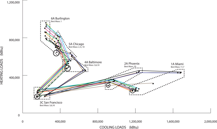
Figure 6.17 Chart of heating over cooling loads for 12 different buildings across six climates.
What one can observe in the graph is the behavior of each building form’s geometric properties across and within the climate zones. One way to describe the spread of results is to say that those with more variation (in Miami, for instance) have a higher sensitivity, whereas those with a smaller variation (e.g., those in San Francisco) have a lower sensitivity. Within those climates with higher sensitivity and a greater spread of results, it is easy to eliminate the poorly performing options, narrowing the range to those with better results. A city like San Francisco, on the other hand, has a lower sensitivity and a smaller difference between the heating and cooling results for different building forms. Simply viewing their energy performance alone does not provide a clear answer, however, so another metric such as daylighting may be a more useful factor in deciding which building mass may be ideal.
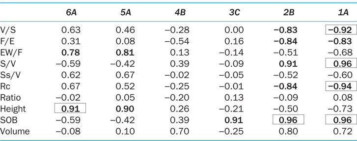
Another observation from the correlation of data, shown in Table 6.18, is that there is no single geometric variable clearly attributed to affecting the performance of this building type across the climates. Within the colder climates (6A and 5A), those masses with more exterior wall (EW/F) or height affect energy performance the most. Within the warmer climates (2B and 1A), however, it is compactness—higher S/V values, lower V/S and F/E values, and more surface area (SOB)—that has the greatest effect on energy performance. However, given another set of criteria in the BEM simulations or site conditions, these results might also vary.
Table 6.18 Statistical correlation of geometric indices and climate zones for the buildings in Figure 6.4.
Self-Shading Mass
Another design concept for reducing energy consumption in hotter climates or for internally loaded buildings would be to shade the building. A design concept known as a self-shading building form, the building’s specific geometry creates shadows on other parts, thereby reducing solar exposure by casting those building elements in shadow.
By using the aggregation of masses to achieve this effect, the design approach creates a self-shaded building form. One way of doing this is by stacking floor plates on top of one another to achieve the total building square footage. As the various plates overhang and overlap, they shade other plates, thus reducing the building’s overall EUI. The concept is relatively simple in that it minimizes the amount of the building’s surface area exposed to the sun at any given time over the course of the year or day simulated. The example shown in Figure 6.19 was submitted as part of an international design competition, and yielded an pEUI of 22, the lowest of any in the competition. Part of the iterative design process involved scripting the program and compositional approach in Grasshopper with the goal of reaching the minimal EUI while maintaining the total square footage. By maintaining the building’s material, operational, and mechanical system as constant, this script was able to produce the lowest EUI mass of any other design approach. Early experiments of the self-shading script are shown in Figure 6.20.
The core ideas within the self-shading of a building form have a history developed by Ralph Knowles’s academic work in the 1960s and 1970s. His studies on the geometric aggregation of spaces in the Native American community of Acoma Pueblo informed ideas involving structures that respond to the sun. His students manipulated different types of geometry based on seasonal exposure to the sun to create complex building forms and shapes. In Figure 6.21, the upturned surface on the left side faces south, with the other side facing east, and the geometry of the façade responds to solar insolation and orientation.
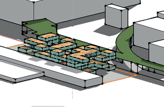
Figure 6.19 BEM example of a self-shaded building by co-author Kaveh Bandhosseini.
Figure 6.20
A range of scripted autonomously generated shading forms by co-author Kaveh Bandhosseini.
Figure 6.21
Ralph Knowles, Energy and Form: An Ecological Approach to Urban Growth, Figure 7.14, page 146, © 1975 Massachusetts Institute of Technology, used with permission of the MIT Press.
Architects in the 1985 text Design of Energy-Responsive Commercial Buildings continued to explore Knowles’s ideas. A case study of William Morgan Architects’ Federal Building in Ft. Lauderdale, Florida demonstrates self-shading in the formal response of the building form that shades the glass. All windows are located under broad overhangs or within notches carved from the building’s corners, and the exposed perimeter walls are solid and opaque.16
Daylight and Energy Optimization
Within fenestration, designers attempt to combine the material characteristics of the glazing, WWR, and shading device design. To illustrate this process, we follow with a BEM example of how the shading devices identified above affect interior daylighting and overall energy use (in most BEM tools, daylighting is a separate entity that doesn’t factor directly into energy consumption).
The sample we evaluate uses a 45-foot cube, a three-story office building placed within six climate zones. We vary the shading devices, as shown in Figure 6.16, on each side of this all-glass volume. At the outset we had an EUI of 91, with the daylighting metrics showing 100 percent sDA (great!) but also 100 percent ASE (bad). The goal was to maintain a high sDA value while minimizing ASE, simultaneously reducing energy consumption. Throughout the exercise, all other factors remained constant. Testing the different shading devices across a range of climates produced a best result of an ASE of 74 and an EUI of 77. While not dramatic, this process does demonstrate the effects shading devices have on reducing unwanted glare and conserving energy.

Figure 6.22
Visual comparison of the all-glass baseline sDA (left) against the best sDA result from shading devices (right).
Iterative testing of the shading devices used an instance of a shading device system from the design software reloaded into energy modeling software (Figure 6.23). This process allowed quick feedback to test different design considerations. Since the energy and daylighting metrics respond alongside the design decisions, we were able to reach easy and quick conclusions. There are ways to
Figure 6.23 Instance of shading device loaded into design software to simulate lighting and energy consumption.
further this exploration through variations in the depth and spacing of the shading devices to achieve an optimal minimum ASE or EUI.

Figure 6.24 Chart showing the percentage difference between sDA and ASE values for seven fixed shading devices across six U.S. locations.
Across all the examples, the sDA remained at 100 percent; Figure 6.24 shows the difference between the ASE and sDA values. Based on the results, almost all of the shading devices have some impact on reducing ASE, but the triangular shading device reduced glare the most. Since our baseline building is all glass, the next design step could evaluate the daylighting metrics alongside a reduction in the glazing amount to see how much more we can reduce the ASE and EUI values.