Objective 5.4—Configure and Manage Logical Routers
This chapter covers all or part of the following VCP6-NV exam blueprint topics:
Objective 5.4—Configure and Manage Logical Routers
Now that we know what a logical router is and how to deploy it, let’s see it in action by doing some packet walks. The packet walks are going to be for east-west traffic for virtual machines in different subnets, while in the same host and different hosts. We also have a packet walk where we see what happens when a virtual machine vMotions during an active flow.
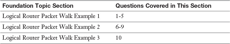
The “Do I Know This Already?” quiz allows you to assess whether you should read this entire chapter or simply jump to the “Exam Preparation Tasks” section for review. If you are in doubt, read the entire chapter. Table 8-1 outlines the major headings in this chapter and the corresponding “Do I Know This Already?” quiz questions. You can find the answers in Appendix A, “Answers to the ‘Do I Know This Already?’ Quizzes.”
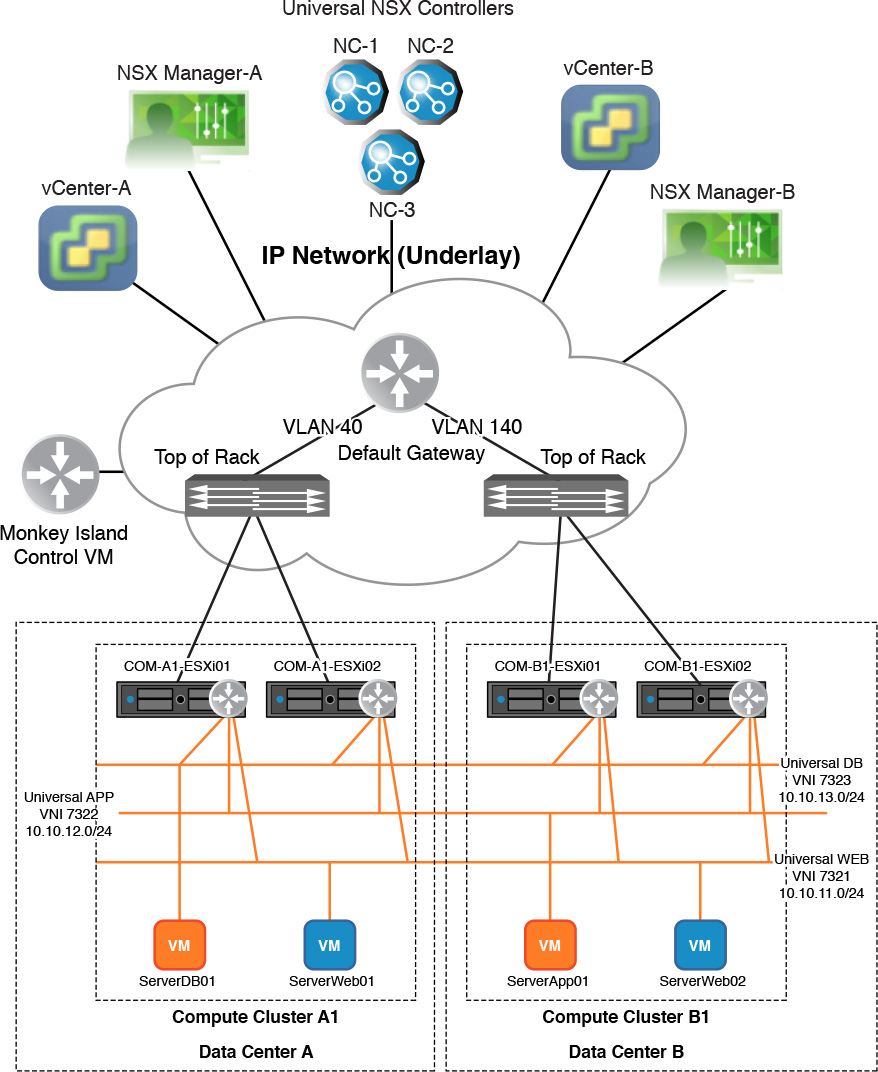
In Figure 8-1, COM-A1-ESXi01 and COM-A1-ESXi02 are part of Compute Cluster A1. Hosts COM-B1-ESXi01 and COM-B1-ESXi02 are part of Compute Cluster B1. Virtual machines SERVERWEB01 and SERVERDB01 are running in hosts in Compute Cluster A1. Virtual machines SERVERWEB02 and SERVERAPP01 are running in hosts in Compute Cluster B1. All virtual machines are connected to logical switches as depicted in the diagram. A universal logical router, named Monkey Island, is configured to have LIFs in all three logical switches and is the default gateway for each segment.
Figure 8-1 Reference diagram for “Do I Know This Already” quiz
Use Figure 8-1 to answer the following questions.
1. Virtual machine SERVERWEB01, running on ESXi host COM-A1-ESXi01, is powered off and SERVERWEB02 takes over the handling of web traffic. SERVERWEB02 is running in ESXi host COM-B1-ESXi02. SERVERDB01 is running in ESXi host COM-A1-ESXi01.
Based on the diagram, which statement describes the action that will be taken with the Monkey Island logical router?
a. The logical router Monkey Island moves the LIF connected to the WEB logical switch in ESXi host COM-A1-ESXi01 to the WEB logical switch in ESXi host COM-B1-ESXi02.
b. ESXi host COM-A1-ESXi01 loses its copy of the Monkey Island logical router.
c. ESXi host COM-B1-ESXi02 gains a copy of the Monkey Island logical router with LIFs connected to only the WEB and DB logical switches.
d. ESXi host COM-A1-ESXi01 and COM-B1-ESXi02 have the same copy of the Monkey Island logical router.
2. Virtual machines SERVERWEB02 and SERVERDB01 are both powered on and are running on the same ESXi host. SERVERWEB02 sends a packet to SERVERDB01.
Based on the diagram, what is the destination MAC address of the frame sent by SERVERWEB02?
a. It is a broadcast, FFFF.FFFF.FFFF.
b. The MAC address of SERVERDB01.
c. The vMAC address of the LIF connected to the WEB logical switch.
d. The pMAC address of the LIF connected to the WEB logical switch.
3. Virtual machines SERVERWEB02 and SERVERDB01 are both powered on and running on the same ESXi host. SERVERWEB02 sends a packet to SERVERDB01.
Based on the diagram, what is the destination MAC address of the first frame sent by Monkey Island using the LIF connected to the DB logical switch?
a. It is a broadcast, FFFF.FFFF.FFFF.
b. The MAC address of SERVERDB01.
c. The vMAC address of the LIF connected to the DB logical switch.
d. The pMAC address of the LIF connected to the DB logical switch.
4. Virtual machines SERVERWEB02 and SERVERDB01 are both powered on and running on the same ESXi host. SERVERWEB02 sends a packet to SERVERDB01. SERVERDB01 has not sent any frames of its own.
Based on the diagram, what is the destination MAC address of the first frame sent by SERVERDB01 as a result of the packet just received from SERVERWEB02?
a. It is a broadcast, FFFF.FFFF.FFFF.
b. The MAC address of SERVERWEB02.
c. The vMAC address of the LIF connected to the DB logical switch.
d. The pMAC address of the LIF connected to the DB logical switch.
5. Virtual machine SERVERAPP01 is running on ESXi host COM-B1-ESXi02.VMware Tools is not installed. SERVERAPP01 sends an ARP reply back to the Monkey Island logical router over logical switch APP.
Based on the diagram, what does the Switch Security module do with the ARP reply frame?
a. The Switch Security module snoops the ARP reply and hands the frame to the Monkey Island logical router copy running on ESXi host COM-B1-ESXi02.
b. The Switch Security module snoops the ARP reply and sends an IP report to the Primary NSX Manager.
c. The Switch Security module snoops the ARP reply and sends an IP report to the Universal NSX Controller Layer 2 Master.
d. The Switch Security module snoops the ARP reply and sends an IP report to the Universal NSX Controller responsible for logical switch APP.
6. Virtual machines SERVERWEB01 and SERVERAPP01 are both powered on.
Based on the diagram, how many LIFs will be configured on the Monkey Island logical router copy running on the same ESXi host where SERVERAPP01 is running?
a. 1
b. 2
c. 3
d. 4
7. Virtual machines SERVERWEB01 and SERVERAPP01 are just powered on. SERVERWEB01 sends a packet to SERVERAPP01.
Based on the diagram, which copy of the Monkey Island logical router sends the ARP request to SERVERAPP01?
a. The copy on the ESXi host where SERVERAPP01 is running, using the LIF connected to the APP logical switch.
b. The copy on the ESXi host where SERVERAPP01 is running, using the LIF connected to the WEB logical switch.
c. The copy on the ESXi host where SERVERWEB01 is running, using the LIF connected to the APP logical switch.
d. The copy on the ESXi host where SERVERWEB01 is running, using the LIF connected to the WEB logical switch.
8. Virtual machine SERVERDB01 receives a frame from SERVERAPP01 in Compute Cluster B1.
Based on the diagram, when SERVERDB01 sends a response packet, which logical switch’s VNI is included in the VXLAN frame back to Compute Cluster A1?
a. The APP logical switch.
b. The DB logical switch.
c. No VNI is included.
d. The WEB logical switch.
9. The Monkey Island logical router receives an ingress packet from the LIF connected to the APP logical switch. There are no security breaches and all virtual machines are operating as designed.
Based on the diagram, which statement is true regarding the ingress packet?
a. The packet indicates that SERVERWEB01 or SERVERWEB02 is communicating with SERVERAPP01.
b. The packet originated from either SERVERWEB01 or SERVERDB01.
c. The packet is not destined for SERVERAPP01.
d. The packet was received by the copy of the Monkey Island logical router running on ESXi host COM-B1-ESXi02.
10. Virtual machine SERVERWEB02 undergoes a vMotion migration while having an active conversation with SERVERAPP01.
Based on the diagram, what is the impact to the conversation with SERVERAPP01?
a. The destination ESXi host sends the NSX Controller an ARP query for SERVERAPP01’s IP.
b. SERVERAPP01 has to send a new ARP request for SERVERWEB02’s MAC.
c. The Monkey Island logical router on the source ESXi host forwards its ARP tables to the destination ESXi host.
d. The Switch Security module’s ARP entry for SERVERWEB02 on the source ESXi host is sent to the destination ESXi host’s Switch Security module.
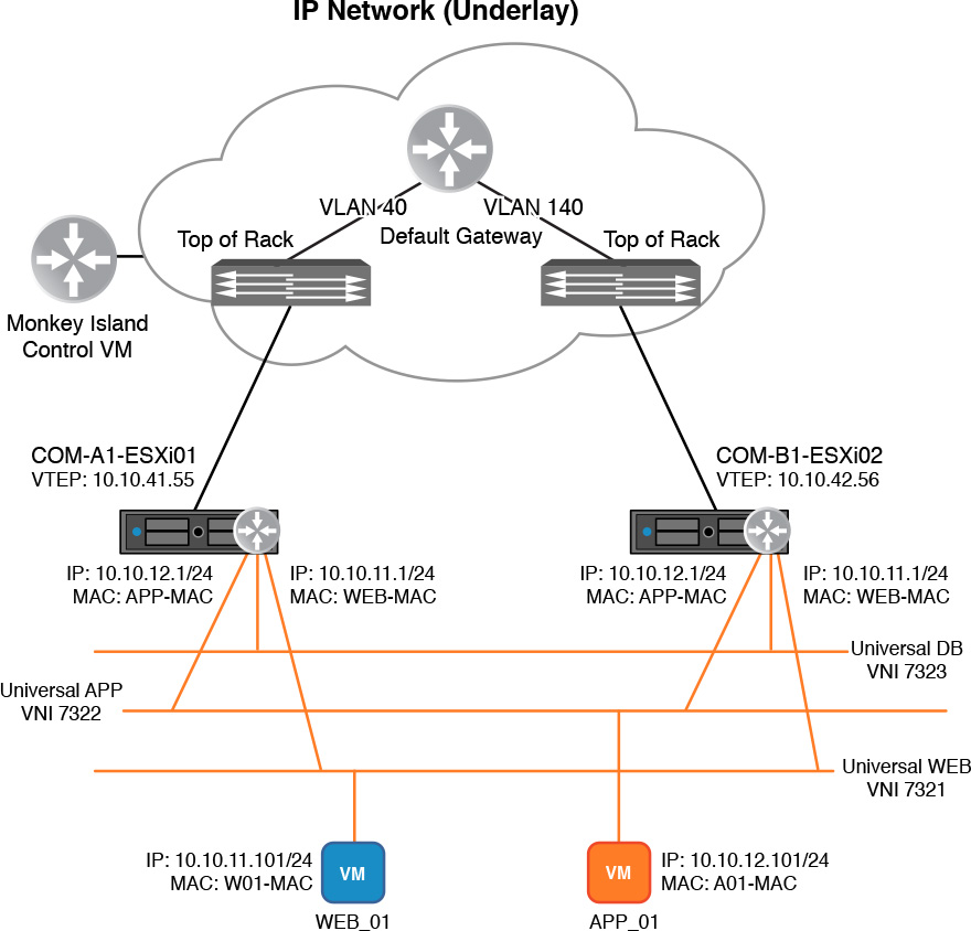
In this section we review some packet walks involving east-west communications among virtual machines connected to different subnets. Each packet walk shows a different aspect of the process the logical router follows to route packets. All packet walks reference a derivative of Figure 8-2, with some figures including different step numbers relevant to the packet walk.
Figure 8-2 has two ESXi clusters, in the same universal transport zone, all configured to support NSX.
Reminder: A distributed logical router and a universal logical router are functionally identical in the data plane. The steps in these packet walks would be the same if we were using a distributed logical router.
Two data centers.
Two vCenters, one per data center.
Two NSX Managers, one per vCenter.
Two ESXi host clusters, one per vCenter, with two ESXi hosts in each.
Each ESXi host cluster has its own vDS with a single dvUplink, which is also used for the portgroups backing the logical switches.
There are three universal NSX Controllers.
Each ESXi host has IP connectivity via the Management VMkernel port to all NSX Controllers, their corresponding NSX Manager, and vCenter.
Each ESXi host is shown with a single VMNIC to the physical network.
ESXi host management, vMotion, IP storage, and VXLAN encapsulated traffic traverses this interface.
ESXi host management traffic uses VLAN 10 in Santo Domingo Data Center and VLAN 110 in Tampa Data Center.
vMotion traffic uses VLAN 20 in Santo Domingo Data Center and VLAN 120 in Tampa Data Center.
IP storage traffic uses VLAN 30 in Santo Domingo Data Center and VLAN 130 in Tampa Data Center.
Cluster A1 uses VLAN 40 for VXLAN traffic encapsulation.
Cluster B1 uses VLAN 140 for VXLAN traffic encapsulation.
Web logical switch uses VNI 7321.
App logical switch uses VNI 7322.
DB logical switch uses VNI 7323.
The Monkey Island logical router is the default gateway for the Web, App, and DB subnets.
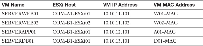
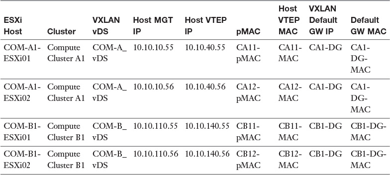
Table 8-2 shows where each virtual machine is running, its IP address, and its MAC address.
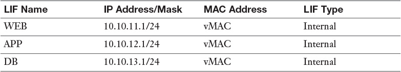
Table 8-3 shows the LIFs of the logical router Monkey Island.
Note
The MAC address for all three LIFs is the same, the vMAC 02:50:56:56:44:52.
Table 8-4 shows each ESXi host’s management IP address, VTEP IP address, and VTEP MAC address.
Note
The VXLAN vDS has a single dvUplink, thus each ESXi host has a single pMAC.
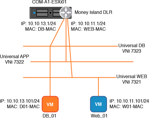
In this packet walk, virtual machine SERVERWEB01 sends a packet to virtual machine SERVERDB01, which then responds back to SERVERWEB01. Assume the following to be true:
SERVERWEB01 and SERVERDB01 have just powered on and have not sent any traffic.
SERVERWEB01 and SERVERDB01 are running on ESXi host COM-A1-ESXi01.
SERVERWEB01 and SERVERDB01 have a default gateway of .1 in their respective subnets.
Monkey Island is the default gateway for SERVERWEB01 and SERVERDB01.
SERVERWEB01 knows the IP of SERVERDB01.
Figure 8-3 shows the logical view of the scenario for Logical Router Packet Walk Example 1.
Step 1. SERVERWEB01 notices the IP of SERVERDB01 is in a different subnet from its own and sends an ARP request for its default gateway’s MAC address.
That is Monkey Island’s LIF in the web logical switch.
Step 2. As it is a broadcast, the ARP request is received by Monkey Island’s WEB LIF in VNI 7321 in COM-A1-ESXi01.
SERVERWEB01’s Switch Security module knows this ARP request is for the logical router thus the ARP request is not forwarded to all other VTEPs in the VTEP table. (I told you the Switch Security module plays nice with the logical switch...and the logical router, too.)
Step 3. Monkey Island in COM-A1-ESXi01 sends back a unicast to SERVERWEB01 with the ARP reply, with a source MAC of vMAC.
Step 4. SERVERWEB01 receives the ARP reply and uses the information to create the packet to send to SERVERDB01.
Source IP: 10.10.11.101
Destination IP: 10.10.13.101
Source MAC: W01-MAC
Destination MAC: vMAC
Step 5. Monkey Island receives the frame in the WEB LIF in COM-A1-ESXi01 and discards the Layer 2 header after confirming that the destination MAC address is the WEB LIF’s.
Step 6. Monkey Island, in COM-A1-ESXi01, then reads the destination IP and searches for the most specific match in the routing table.
The most specific route in the routing table matches the subnet in the DB LIF. This is commonly referred to as “directly connected” or “directly attached.”
Step 7. Monkey Island then looks in its local ARP table for an entry for IP 10.10.13.101.
By “local” ARP table I mean the logical router’s ARP table in ESXi host COM-A1-ESXi01.
Step 8. Not finding an entry, Monkey Island sends out an ARP request for IP 10.10.13.101.
Remember that SERVERDB01 has sent no traffic and therefore Monkey Island couldn’t have an ARP entry for it yet.
The ARP request is sent over the DB LIF in COM-A1-ESXi01.
Important: As of NSX 6.2, the source MAC for the ARP request is the vMAC (before it used to be the pMAC).
Step 9. SERVERDB01 receives the ARP request and sends back a unicast ARP reply to Monkey Island’s DB LIF in COM-A1-ESXi01.
The Switch Security module in SERVERDB01 snoops the ARP reply and sends an IP report to the universal NSX Controller responsible for the DB logical switch.
Step 10. Monkey Island receives the ARP reply and uses the information to forward the packet to SERVERDB01.
The packet is forwarded over the DB LIF.
Source IP: 10.10.11.101
Destination IP: 10.10.13.101
Source MAC: vMAC
Destination MAC: D01-MAC
Logical routers use the vMAC as the source of all packets sent over LIFs.
Step 11. SERVERDB01 receives the frame and processes it.
Note
Steps 12 through 14 only take place if the OS in SERVERDB01 does not add an ARP entry when it receives, and replies, to an ARP request. Most major OSes do not do this.
Step 12. SERVERDB01 wants to reply back to SERVERWEB01, notices that it is in a separate subnet, and sends an ARP request for its default gateway’s MAC address.
SERVERDB01 sends back an ARP reply to Monkey Island in Step 9, but it does not add DB LIF’s IP/MAC to the ARP table.
This is normal ARP operation of major operating systems to only add a new ARP entry to their ARP table only upon receiving an ARP reply to an ARP request they sent.
Step 13. Monkey Island receives the ARP request over the DB LIF in COM-A1-ESXi01.
Step 14. Monkey Island sends an ARP reply back to SERVERDB01.
Step 15. SERVERDB01 uses the ARP reply info to send the packet to SERVERWEB01.
Source IP: 10.10.13.101
Destination IP: 10.10.11.101
Source MAC: D01-MAC
Destination MAC: vMAC
Step 16. Monkey Island receives the frame in the DB LIF in COM-A1-ESXi01 and discards the Layer 2 header after confirming that the destination MAC address is the DB LIF’s.
Step 17. Monkey Island, in COM-A1-ESXi01, then reads the destination IP and searches for the most specific match in the routing table.
The most specific route in the routing table is directly connected to the WEB LIF.
Step 18. Monkey Island then looks in its local ARP table for an entry for IP 10.10.11.101.
Step 19. Not finding an entry, Monkey Island sends out an ARP request for IP 10.10.11.101 over the WEB LIF.
This is for the same reason as in Step 12.
Important: As mentioned in Chapter 7, “Logical Router,” the logical router’s LIFs are a special vDS port called vdrPort. The vdrPort does not have the Switch Security module, and thus does not enjoy the benefits of ARP suppression.
Step 20. SERVERWEB01 receives the ARP request and sends back a unicast ARP reply to Monkey Island’s WEB LIF in COM-A1-ESXi01.
Step 21. Monkey Island receives the ARP reply and uses the information to forward the packet to SERVERWEB01.
The packet is forwarded over the WEB LIF.
Source IP: 10.10.13.101
Destination IP: 10.10.11.101
Source MAC: vMAC
Destination MAC: W01-MAC
Step 22. SERVERWEB01 receives the frame and processes it.
Step 23. Subsequent traffic from SERVERWEB01 toward SERVERDB01 does not require ARP requests.
As long as the ARP entries don’t age out in SERVERWEB01, SERVERDB01 nor in the local ARP table copies of the logical router where the virtual machines are running. The virtual machines, the copies of the logical router, and the Switch Security module will not age out the ARP entries if they continue to see traffic sourced from the corresponding IPs before the aged-out timer expires, which is 180 seconds (3 minutes). Remember that if Switch Security module ages out an ARP entry, it sends an IP report to the NSX Controller.
You should know what I’m going to say: That was easy! This is your normal routing process taking place between two end systems that have the same entity as their default gateway. In the next example we do another packet walk between two virtual machines with the same router, Monkey Island, as their default gateway but running in different hosts.
In this packet walk, virtual machine SERVERWEB01 sends a packet to virtual machine SERVERAPP01, which then responds back to SERVERWEB01. Assume the following to be true:
SERVERAPP01 has just powered on and has not sent any traffic.
SERVERWEB01 is running on ESXi host COM-A1-ESXi01.
SERVERAPP01 is running on ESXi host COM-B1-ESXi01.
SERVERWEB01 and SERVERAPP01 have a default gateway of .1 in their respective subnets.
Monkey Island is the default gateway for SERVERWEB01 and SERVERAPP01.
SERVERWEB01 knows the IP of SERVERAPP01.
Figure 8-4 shows the logical view of the scenario for Logical Router Packet Walk Example 2.
Step 1. SERVERWEB01 notices the IP of SERVERAPP01 is in a different subnet from its own and sends a packet to SERVERAPP01 using the default gateway ARP entry in its ARP table.
The ARP table entry was created in Logical Router Packet Walk Example 1.
Source IP: 10.10.11.101
Destination IP: 10.10.12.101
Source MAC: W01-MAC
Destination MAC: vMAC
Step 2. Monkey Island receives the frame in the WEB LIF in COM-A1-ESXi01 and discards the Layer 2 header after confirming that the destination MAC address is the WEB LIF’s.
Step 3. Monkey Island, in COM-A1-ESXi01, then reads the destination IP, searches for the most specific match in the routing table, and concludes it is directly connected in the APP LIF.

Step 3 is critical to understanding the functionality of the distributed logical router. The copy of Monkey Island running in COM-A1-ESXi01 does not care in which host SERVERAPP01 is actually located. All that matters is that the IP for SERVERAPP01 is in the subnet directly attached to Monkey Island’s APP LIF.
Step 4. Monkey Island then looks in its local ARP table for an entry for IP 10.10.12.101.
Step 5. Not finding an entry, Monkey Island sends out an ARP request for IP 10.10.12.101.
The ARP request is sent over the APP LIF in COM-A1-ESXi01.
Source IP: 10.10.12.1
Destination IP: 10.10.12.101
Source MAC: vMAC
Destination MAC: FFFF.FFFF.FFFF
Step 6. APP logical switch in COM-A1-ESXi01 receives the ARP request and executes its configured Replication Mode to get the frame sent to all ESXi hosts that need it.
We covered a packet walk for Replication Modes in Chapter 6, “Logical Switch Packet Walks.” Take a few moments to review the different types (Multicast, Unicast, and Hybrid) of Replication Modes used by logical switches to forward BUMs.
Step 7. APP logical switch in COM-B1-ESXi02 receives the ARP request and forwards it to SERVERAPP01.
APP logical switch will not learn MAC address vMAC as coming from VTEP 10.10.40.55.
Little Secret: Before the logical switch processes the ARP request, the logical router Monkey Island in COM-B1-ESXi02 will see the ARP request with a source of the vMAC. Make a note of the ESXi host that sent it, and await for an ARP reply. The logical switch also coordinates with the logical router so it knows vMAC does not belong to a VM. That’s one reason the logical switch never advertises the LIF MAC to the NSX Controller.
Step 8. SERVERAPP01 receives the ARP request and sends back a unicast ARP reply to Monkey Island’s APP LIF.
Source IP: 10.10.12.101
Destination IP: 10.10.12.1
Source MAC: A01-MAC
Destination MAC: vMAC
Step 9. The APP logical switch in COM-B1-ESXi01 sees the ARP reply being sent to the vMAC, and gives it to the local copy of Monkey Island. Using the cached information from step 7, the local copy of Monkey Island in COM-B1-ESXi01 shares the ARP reply, via OOB communications, with the copy of Monkey Island in COM-A1-ESXi01.
Step 10. Monkey Island in COM-A1-ESXi01 receives the ARP update and uses the information to forward the packet to SERVERAPP01 over the APP LIF.
The packet is forwarded over the APP LIF.
Source IP: 10.10.11.101
Destination IP: 10.10.12.101
Source MAC: vMAC
Destination MAC: A01-MAC
Note
Before NSX 6.2, every non-ARP packet sent by a logical switch that would not stay local to the ESXi host used the pMAC as the source MAC address. The pMAC chosen depended on the dvUplink the packet would egress. As of NSX 6.2, all packets sent over a VXLAN LIF use the vMAC as the source MAC.
Step 11. SERVERAPP01 receives the frame and processes it.
Step 12. SERVERAPP01 wants to reply back to SERVERWEB01, notices that it is in a separate subnet, and sends an ARP request for its default gateway’s MAC address.
Review step 12 in Logical Router Packet Walk Example 1 if you are not sure as to why the ARP request is needed.
Step 13. Monkey Island receives the ARP request over the APP LIF in COM-B1-ESXi02.
Step 14. Monkey Island sends back an ARP reply to SERVERAPP01.
Step 15. SERVERAPP01 uses the ARP reply info to send the packet to SERVERWEB01.
Source IP: 10.10.12.101
Destination IP: 10.10.11.101
Source MAC: A01-MAC
Destination MAC: vMAC
Step 16. Monkey Island in COM-B1-ESXi02 receives the frame in the APP LIF and discards the Layer 2 header after confirming that the destination MAC address is the APP LIF’s.
Step 17. Monkey Island, in COM-B1-ESXi02, then reads the destination IP and searches for the most specific match in the routing table.
The most specific route in the routing table is directly connected to the WEB LIF.
Step 18. Monkey Island then looks in its local ARP table for an entry for IP 10.10.11.101.
Step 19. Not finding an entry, Monkey Island sends out an ARP request for IP 10.10.11.101.
The ARP request is sent over the WEB LIF in COM-B1-ESXi02.
Source IP: 10.10.11.1
Destination IP: 10.10.11.101
Source MAC: vMAC
Destination MAC: FFFF.FFFF.FFFF
Step 20. Web logical switch in COM-B1-ESXi02 receives the ARP request and follows Replication Mode to get the frame sent to all ESXI hosts that need it.
Step 21. WEB logical switch in COM-A1-ESXi01 receives the ARP request and forwards it to SERVERWEB01.
Monkey Island in COM-A1-ESXi01 notices the ARP request was sent from Monkey Island’s copy in COM-B1-ESXi02.
Step 22. SERVERWEB01 receives the ARP request and sends back a unicast ARP reply to Monkey Island’s WEB LIF in COM-A1-ESXi01.
Source IP: 10.10.11.101
Destination IP: 10.10.11.1
Source MAC: W01-MAC
Destination MAC: vMAC
Step 23. The WEB logical switch in COM-A1-ESXi01 sees the ARP reply being sent to the vMAC and gives it to the local copy of Monkey Island. Via OOB communications, the ARP entry is provided to the copy of Monkey Island in COM-B1-ESXi02.
Step 24. Monkey Island in COM-B1-ESXi02 receives the ARP update over its WEB LIF, and uses the information to forward the packet to SERVERWEB01.
The packet is forwarded over the WEB LIF.
Source IP: 10.10.12.101
Destination IP: 10.10.11.101
Source MAC: vMAC
Destination MAC: W01-MAC
Step 25. SERVERWEB01 receives the frame and processes it.
Step 26. Subsequent traffic from SERVERWEB01 toward SERVERAPP01 does not require ARP requests.
As long as the ARP entries don’t age out in SERVERWEB01, SERVERAPP01 nor in the local ARP table copies of the logical router.
There are a few points that we need to get from this packet walk. The first one is about routers and directly connected subnets. All routers need to find a match in the routing table matching a directly connected subnet so they can put a Layer 2 header in the packet before forwarding it. The logical router follows the same principle. In the case of Ethernet interfaces, once the router has forwarded the packet to the Ethernet switch, inside an Ethernet frame, it is the Ethernet switch’s job to decide the best way to get the frame to the owner of the destination MAC address.
Second, the logical router copy is sent to each ESXi host in the transport zone of the logical switches the LIFs connect to. Each logical router copy in the ESXi hosts has the same LIFs. If this were not the case, the logical router wouldn’t be able to reach all the VMs in the logical switches. For instance, if the copy of Monkey Island in COM-A1-ESXi01 did not have an APP LIF, there would be no way for traffic from SERVERWEB01 to reach SERVERAPP01.
Third, routing packets from VMs is always performed by the copy of the logical router in the ESXi host where the source VM is. In other words, the logical router’s routing is asymmetrical. This asymmetry is not a problem because all logical router copies are making decisions using the (mostly) same routing table.
Fourth, the logical router has little interest in what VXLAN or a VNI are, nor does it care much about them. The job of the logical router is to take ingress traffic, make a routing decision, and forward the packet. The logical switches are the only ones that deal with VXLAN directly. Because the local copy of the logical router performs routing, it means that any VXLAN overlays supporting a flow between two VMs will also be asymmetrical, with the logical switch where the destination VM resides handling the VXLAN encapsulation.
This example covers about every major point there is to know about the logical router. From the logical router perspective, traffic will ingress over one LIF and egress over another LIF. That’s its job and not much more. The part that can lead to confusion in understanding the functionality of the logical router is realizing that the local logical router copy makes the data plane decision using its local copy of its routing table, which it received from the NSX Controller responsible for the logical router. Although each logical router copy has the same routing table (almost always, more on that when we talk about local egress in Chapter 11, “Layer 3 Connectivity Between Virtual and Physical Networks”), each logical router copy is mostly unaware of the existence of the other logical router copies. We cover a bit more on logical router copies becoming aware of each other in Chapter 11 as well.
Let’s do one more packet walk, this time to understand what happens when a VM vMotions. We covered what transpires at Layer 2 during vMotion in Chapter 6. We build on that example to see what happens at Layer 3 when the logical router is the default gateway.
In this packet walk, virtual machine SERVERWEB01 has an active bidirectional traffic flow with virtual machine SERVERAPP01. Assume the following to be true:
SERVERWEB01 is running on ESXi host COM-A1-ESXi01.
SERVERAPP01 is running on ESXi host COM-B1-ESXi01.
SERVERWEB01 and SERVERAPP01 have a default gateway of .1 in their respective subnets.
Monkey Island is the default gateway for SERVERWEB01 and SERVERAPP01.
Monkey Island’s WEB LIF is an Internal LIF.
SERVERWEB01 knows the IP of SERVERAPP01.
Figure 8-5 shows the logical view of the scenario for Logical Router Packet Walk Example 3.
Step 1. DRS or a user initiates vMotion for SERVERWEB01 toward COM-A1-ESXi02.
Step 2. The moment vMotion completes, ESXi host COM-A1-ESXi02 sends an RARP over the WEB logical switch with SERVERWEB01’s MAC address.
Remember that after vMotion completes, COM-A1-ESXi01 sends an “I don’t have MAC address W01-MAC” update to the NSX Controller responsible for the WEB logical switch, while COM-A1-ESXi02 sends an “I have MAC address W01-MAC” to the same NSX Controller. This was covered in Chapter 6. Also, the Switch Security module in COM-A1-ESXi02 receives the ARP entry associated with the vMotioned VM, SERVERWEB01.
Step 3. Immediately after vMotion completes, SERVERWEB01 sends a packet to SERVERAPP01.
Source IP: 10.10.11.101
Destination IP: 10.10.12.101
Source MAC: W01-MAC
Destination MAC: vMAC
Step 4. The copy of Monkey Island in COM-A1-ESXi02 performs routing, determines the destination IP to be directly connected to APP LIF, and sends an ARP request over the APP LIF for 10.10.12.101.
Source IP: 10.10.12.1
Destination IP: 10.10.12.101
Source MAC: vMAC
Destination MAC: FFFF.FFFF.FFFF
Step 5. SERVERAPP01 receives the ARP request and sends a unicast ARP reply to Monkey Island.
SERVERAPP01 has an ARP entry for the vMAC in its ARP table with an IP of 10.10.12.1, thus it makes no changes to its ARP table.
Step 6. Monkey Island in COM-A1-ESXi02 receives the ARP update and uses the information to forward the packet to SERVERAPP01.
Source IP: 10.10.11.101
Destination IP: 10.10.12.101
Source MAC: vMAC
Destination MAC: A01-MAC
Step 7. SERVERAPP01 receives the packet from SERVERWEB01 and replies back to SERVERWEB01.
Source IP: 10.10.12.101
Destination IP: 10.10.11.101
Source MAC: A01-MAC
Destination MAC: vMAC
Step 8. The frame from SERVERAPP01 is received by the copy of Monkey Island in COM-B1-ESXi01, which does routing and concludes the destination IP is directly connected to WEB LIF.
Step 9. With the information in the ARP table, Monkey Island in COM-B1-ESXi01 forwards the packet out of WEB LIF.
Source IP: 10.10.12.101
Destination IP: 10.10.11.101
Source MAC: vMAC
Destination MAC: W01-MAC
vMotions had no impact in the copy of Monkey Island in COM-B1-ESXi01. Thus there should be an ARP entry for SERVERWEB01 in the ARP table.
Step 10. WEB logical switch in COM-B1-ESXi01 forwards the frame to VTEP 10.10.41.56, COM-A1-ESXi02.
WEB logical switch in COM-B1-ESXi01 would have been updated of the new location of MAC address W01-MAC as part of the vMotion process. This was covered in Chapter 6.
Step 11. SERVERWEB01 receives the frame.
During vMotion, the only impact to any active flows is that the local logical router copy in the vMotion destination host, COM-A1-ESXi02, has to send an ARP request. The vMotioned virtual machine’s default gateway MAC address is the same because it is the vMAC, 02:50:56:56:44:52.
This was our last logical router packet walk scenario for east-west traffic between VMs. In previous chapters we covered how logical switches can be used to allow and scale VMs to share an Ethernet broadcast domain even when the ESXi hosts where they are running are separated by Layer 3 boundaries. Now we are seeing how we can extend east-west traffic for VMs in different subnets, transparently to the underlay, and while also running in ESXi hosts separated by Layer 3 boundaries.
Our next step in our exam preparation journey is to discuss ways in which NSX can provide a mechanism to allow VMs to share an Ethernet broadcast domain when deploying VXLAN across a Layer 3 boundary is not an option, and to allow VMs to share an Ethernet broadcast domain with physical workloads. However, before we do this, we need to formally introduce the NSX Edge, which is the topic of the next chapter.
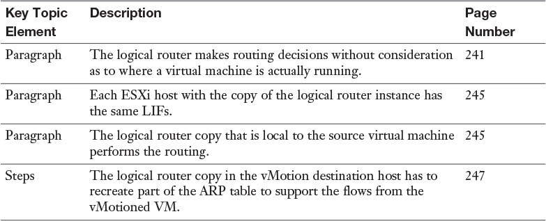
Review the most important topics from inside the chapter, noted with the Key Topic icon in the outer margin of the page. Table 8-5 lists these key topics and the page numbers where each is found.
Define the following key terms from this chapter, and check your answers in the Glossary: