Objective 5.4—Configure and Manage Logical Routers
This chapter covers all or part of the following VCP6-NV exam blueprint topics:
Objective 5.4—Configure and Manage Logical Routers
Objective 8.1—Differentiate single and Cross-vCenter NSX deployments
Objective 8.2—Determine Cross-vCenter Requirements and Configurations
Objective 10.3—Troubleshoot Common NSX Component Issues
We learned how NSX provides ways in which two virtual machines (VMs) can be in the same Ethernet broadcast domain regardless of the location of the ESXi hosts (where the VMs are running). In today’s data center, most of the traffic between VMs does not take place in the same broadcast domain, where the VMs are in the same subnet, but rather between VMs in different broadcast domains or subnets.
The traditional model of having an entity acting as the default gateway eliminates some of the benefits of using logical switches. Think about it: Without NSX all traffic that leaves a broadcast domain would have to be pinned back to the default gateway, wherever it is physically located. In this chapter, you learn about NSX’s logical routers. You learn how the logical routers can be leveraged to handle east-west traffic between VMs in different subnets.
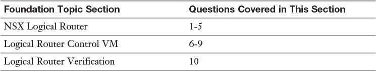
The “Do I Know This Already?” quiz allows you to assess whether you should read this entire chapter or simply jump to the “Exam Preparation Tasks” section for review. If you are in doubt, read the entire chapter. Table 7-1 outlines the major headings in this chapter and the corresponding “Do I Know This Already?” quiz questions. You can find the answers in Appendix A, “Answers to the ‘Do I Know This Already?’ Quizzes.”
1. In which plane does the logical router reside?
a. Management plane
b. Forwarding plane
c. Data plane
d. Control plane
2. How many distributed logical router instances are supported by an ESXi host?
a. 100
b. 1,000
c. 1,200
d. 2,400
3. How many universal logical router instances are supported in an NSX domain?
a. 100
b. 1,000
c. 1,200
d. 2,400
4. Which of the following interfaces is not supported by a universal logical router?
a. Uplink VXLAN LIF
b. Internal VXLAN LIF
c. Uplink VLAN LIF
d. vdrPort
5. Which two types of interfaces can be configured on a logical router? (Choose two.)
a. Internal
b. External
c. Downlink
d. Uplink
6. How many logical router control VMs are supported by the universal logical router?
a. 1
b. 2
c. 4
d. 8
7. In which plane does the distributed logical control VM reside?
a. Management plane
b. Forwarding plane
c. Data plane
d. Control plane
8. How much memory does the control VM have?
a. 512 MB
b. 1 GB
c. 2 GB
d. 4 GB
9. A universal logical router is deployed in a cross-vCenter NSX domain with three vCenter servers. How many universal logical router control VMs could be deployed in this scenario?
a. 1 control VM, to be deployed to any of the three vCenter servers
b. 3 control VMs, to be deployed one to each vCenter server
c. 2 control VMs in Edge HA mode, to be deployed to the vCenter server paired with the Primary NSX Manager
d. 2 control VMs in Edge HA mode, to be deployed to at least two of the three vCenter servers
10. Which entity does not have a copy of the logical router’s routing table?
a. ESXi host
b. NSX Manager
c. NSX Controller
d. Control VM
The NSX logical router, or just logical router for short, is a router whose data plane runs in the ESXi host kernel. We installed the logical router module in the ESXi host during host preparation in Chapter 4, “VXLAN, NSX Controllers, and NSX Preparation;” it is part of the VXLAN VIB. What makes the logical router different from your traditional router is that it is 1) distributed and 2) has a separate entity handling the control plane.
The logical router has a data plane running in the kernel of each ESXi host that has a copy of it. If two ESXi hosts are running a copy of the same logical router instance, it is still considered one router. The copies are almost identical to each other. We talk a bit about the exceptions to being identical later in this chapter. The logical router is similar to how two ESXi hosts have different data planes for the same logical switch or vDS.
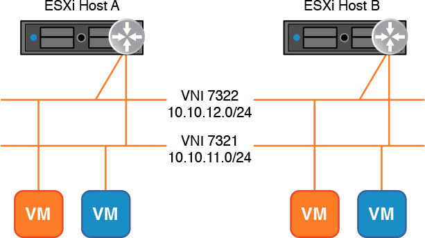
Figure 7-1 shows a logical router instance with two connections to logical switches 7321 and 7322. There are two ESXi hosts, each with a powered on VM connected to each logical switch. The logical router instance copies in each ESXi host are similar.

A single ESXi host can run 100 different logical router instances. Each logical router instance in the ESXi host is totally and completely independent and separate from all other logical router instances running in the same ESXi host. The closest analogy that comes to mind is a physical router with multiple Virtual Routing and Forwarding (VRF) tables. Each VRF table is independent of the other. An NSX domain can have a total of 1,200 different logical router instances running. Each logical router can also have 1,000 logical interfaces (LIFs).
Each logical router is assigned, by the NSX Controller Layer 3 master, to an NSX Controller to manage its control plane. The NSX Controller responsible for the logical router instance keeps a copy of the master routing table for the logical router. The NSX Controller pushes a copy of the routing table to each ESXi host running an instance of the logical router. All copies of the logical router in each ESXi host with the same Locale ID have the same routing table. We cover Locale IDs later in this chapter in the section “Locale ID.” If there is a change in the routing table, the responsible NSX Controller pushes the updated routing table to the corresponding ESXi hosts running the logical router.
A logical router’s LIF can connect to a logical switch or dvPortgroup. A logical router’s LIF can’t connect to a standard portgroup. Recall from Chapter 5, “NSX Switches,” a logical switch is represented by a dvPortgroup. Thus a logical router LIF can connect to a VXLAN backed dvPortgroup (logical switch) or a VLAN backed dvPortgroup.
Every ESXi host in the transport zone of the logical switch an LIF connects to gets a copy of the logical router instance. In the case of an LIF connecting to a VLAN backed dvPortgroup, but has no LIFs connected to a logical switch, all ESXi hosts that belong to the same vDS where the dvPortgroup is get a copy of the logical router instance.
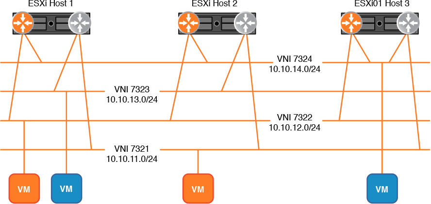
Figure 7-2 shows three ESXi hosts, four logical switches in the same transport zone, and two logical router instances. The four powered-on VMs connect to the four logical switches, one VM per logical switch. Regardless of the placement of the VMs, the NSX Controller places copies of both logical router instances on all three ESXi hosts.
The logical router can have two types of LIFs:
Internal LIF: Intended for connections to logical switches that have virtual machines. We refer to these Layer 2 segments with an Internal LIF as internal segments. No Layer 3 control plane traffic, such as OSPF hellos, should ever be seen in the internal segment.
Uplink LIF: Intended to connect to logical switches that have other routing entities connected to them, such as the NSX Edge Services Gateway, as well as entities participating in Layer 3 control plane traffic, such as the logical router control VM. We discuss the logical router control VM later in this chapter. A logical router can have up to eight Uplink LIFs. We refer to these Layer 2 segments with an Uplink LIF as uplink segments. No non-appliance virtual machine should be connecting to an uplink segment.
When connecting an LIF to a logical switch, the LIF is also referred to as a VXLAN LIF. When connecting an LIF to a VLAN backed dvPortgroup, the LIF is also referred to as a VLAN LIF. Both the Internal and Uplink LIFs can be connected to a VLAN backed dvPortgroup instead of logical switches. The benefits of having a VLAN Internal LIF are between minimal to none, and it is generally not a good idea as it constrains the egress points for Layer 3 traffic and would require all clusters in the same transport zone to use the same vDS. The VLAN Uplink LIF could be used so the logical router can do routing directly with the physical network. We review this design further in Chapter 11, “Layer 3 Connectivity Between Virtual and Physical Networks.”
Each copy of the logical router instance in the ESXi hosts gets at least two MAC addresses. One is called the vMAC, and it is the same MAC in all logical router copies. The vMAC is 02:50:56:56:44:52. The other MAC addresses are called the pMAC, assigned one per dvUplink based on the Teaming Policy selected during host preparation. Each pMAC is different in each copy of the logical router. The pMAC is generated by each ESXi host independently and has VMware’s Organization Unique ID (OUI) of 00:50:56. When the logical router sends an ARP request from an LIF or when it sends an ARP reply for an IP of one of its LIFs, it responds with the vMAC. Also, for egress traffic from any of its VXLAN LIFs, it uses the vMAC as the source MAC address. For all other traffic, including traffic over VLAN LIFs, it uses the corresponding pMAC. Chapter 11 covers pMAC over VLAN LIFs in more detail.
A VLAN LIF can only connect to a dvPortgroup configured with a VLAN number, other than 0 and 4095, and is present in all ESXi hosts that have a copy of the logical router instance. In other words, all ESXi hosts that have a copy of the logical router instance must be part of the same vDS where the dvPortgroup exists.
Not only do all copies of the logical router instance use the same vMAC of 02:50:56:56:44:52, but ALL logical router instances do as well. This is one reason why two LIFs, from the same logical router or from different logical routers, can’t be connected to the same logical switch.
There are two types of logical routers. A logical router can only connect to global logical switches or universal logical switches, but not both at the same time. If a logical router connects to global logical switches it is called a distributed logical router. If a logical router connects to a universal logical switch it is called a universal logical router (ULR). A ULR does not support VLAN LIFs, only VXLAN LIFs. The Primary NSX Manager in the Cross vCenter NSX domain is the only one that can deploy the ULR. At time of deployment you must select which type of logical router you are deploying.
Assume you have a VM connected to a logical switch, a logical router with an internal LIF in the same logical switch, and the VM has a default gateway of the LIF’s IP. When the VM sends an ARP request for its default gateway’s MAC, the logical router in the same ESXi host where the VM is running sends back an ARP reply with the vMAC.
In this case, when the virtual machine vMotions, the MAC address of the VMs’ default gateway will be the same at the destination host because it is the vMAC. The same is true if the VM is connected to a universal logical switch with a ULR for its default gateway.
The pMAC is the one of three differences that can be found in the copies of the logical router instances in each ESXi host. The other differences occur when using Locale IDs, in the case of universal logical routers, and when doing Layer 2 Bridging, in the case of distributed logical routers. We review Layer 2 Bridging in Chapter 10, “Layer 2 Extensions.” Everything else in the logical router instance’s copies is identical.
It is not possible to connect a logical router to logical switches in different transport zones, as there might be a cluster in one transport zone that is not a member of the other transport zone. Thus, it wouldn’t be possible to have the same identical copy of the logical router in all of the ESXi hosts in both transport zones.
For each logical router instance created, at least one virtual appliance called the Logical Router Control Virtual Machine, or Control VM for short, is deployed...if you want—more on this shortly. The Control VM’s job is to handle the dynamic component of the logical router’s control plane by making routing neighbor adjacencies and creating the forwarding database, or routing table, for dynamic entries. A Control VM does not perform control plane functions for more than one logical router instance; however, in the case of the ULR, you may deploy multiple independent Control VMs, one per NSX Manager in the Cross vCenter domain.
After the Control VM puts together the dynamic routing table, a copy of it needs to be given to each ESXi host that is running a copy of the logical router instance. The only entity that actually knows of all the ESXi hosts that are running the copy of the logical router is the NSX Controller responsible for the logical router instance. Thus the Control VM forwards the dynamic routing table to the NSX Controller, which would merge it with its copy of the static routing table to create the master routing table. A copy of the master routing table is forwarded by the NSX Controller to the ESXi hosts that are running a copy of the logical router instance. Future dynamic routing table updates follow the same communication path.
So I teased you by saying that you can choose whether to deploy a Control VM. The Control VM is a modified NSX Edge appliance that consumes compute and storage resources in an ESXi host somewhere. Chapter 9, “NSX Edge Services Gateway,” begins coverage of the NSX Edge. The Control VM has 1 vCPU, 512 MB of RAM, and 500 MB of thin-provisioned storage. If you are not interested in having the logical router do any dynamic routing, you don’t need the Control VM. However, once you deploy a logical router without a Control VM, you can’t go back and add the Control VM later. It is a “take it or leave it” kind of deal. If you choose to deploy a Control VM, the Control VM won’t do much, if anything, until you configure a dynamic routing protocol.
Do you recall the Uplink LIF? That’s the segment where all the routing control plane would be taking place, such as forming OSPF adjacencies. The logical router instance itself is a data plane entity and therefore can’t do any dynamic control plane, such as running BGP. To participate in the routing control plane process the Control VM automatically has one of its interfaces connected to the uplink segment of the Uplink LIF. When I say the Control VM would connect itself, I mean the NSX Manager selects one of the available Control VM interfaces to connect to the uplink segment and asks vCenter to make the connection. The Control VM should never have one of its interfaces connected to an internal segment, with one optional exception: You may connect the Control VM’s High Availability (HA) interface to an internal segment. Prior to NSX 6.2, the High Availability interface was called the Management interface.
Why, you ask, does the Control VM need to have one of its interfaces connected to the uplink segment? Because the Control VM needs a Layer 2 path to exchange control plane routing information with whichever device it needs to communicate with. For example, if you configure OSPF in the Uplink LIF, the Control VM needs to exchange Layer 2 OSPF LSAs over the uplink segment.
The Control VM, being that it is a virtual machine, has 10 interfaces, one of which must be reserved for the HA interface. The HA interface is used to get SSH access to the Control VM as well as for syslog. By accessing the Control VM via SSH or via the VM console in the vSphere Web Client, you can get CLI access to view the Control VM’s interfaces as well as the IPs of logical router interfaces, the routing table, and routing process neighbors. You can also perform control plane debugging from the CLI. You cannot make configuration changes for the logical router from the Control VM CLI.
Any routing peers the Control VM has will not be aware that the logical router and the Control VM are two different entities. We review how dynamic routing is achieved in Chapter 12, “Routing Protocols.”
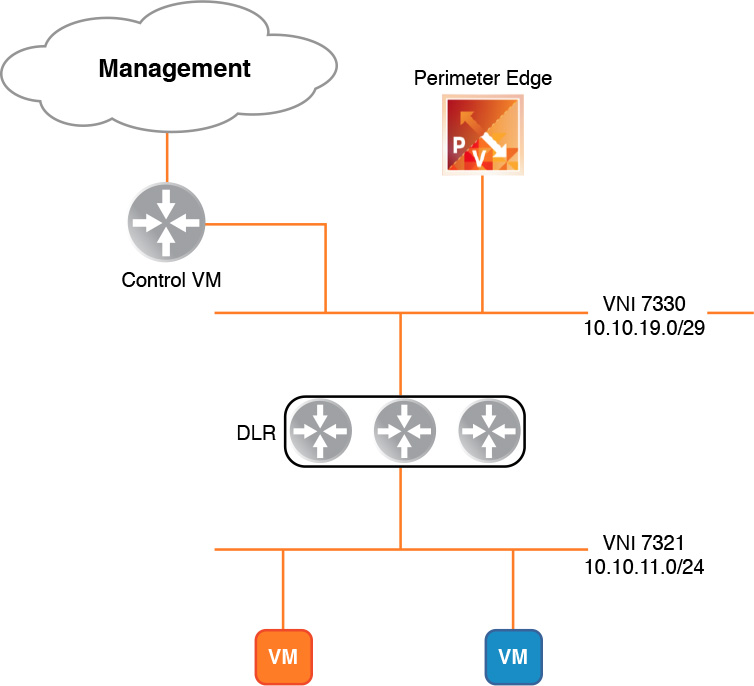
Figure 7-3 shows a logical view of the Control VM with an interface connected to an uplink segment, where an NSX Edge Services Gateway is connected, and the HA interface connected to a management segment.
The logical router is created by the NSX Manager, either by use of the vSphere Web Client or via the NSX APIs.
Before you deploy the logical router, you must have the following:
The role of enterprise administrator or NSX administrator.
The NSX Controller cluster must be up and available.
A VNI pool must have been created.
To deploy the logical router using the vSphere Web Client, follow these steps:
Step 1. From the NSX Home page select NSX Edges.
Step 2. In the NSX Manager drop-down menu, select the NSX Manager that will be deploying the logical router.
If you want to deploy a ULR, you must select the Primary NSX Manager.
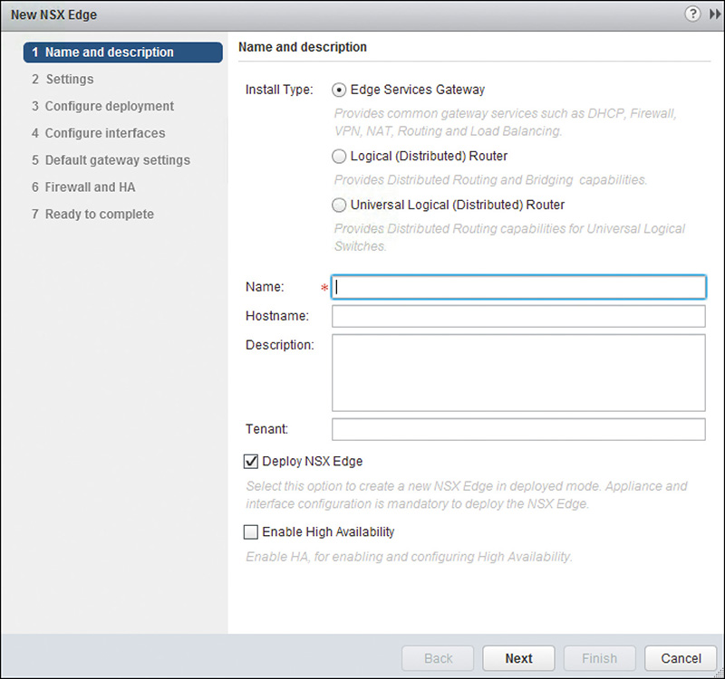
Step 3. Click the green + icon and wait for the New NSX Edge Wizard to open, as shown in Figure 7-4.
Step 4. In the Name and Description step, fill out these values:
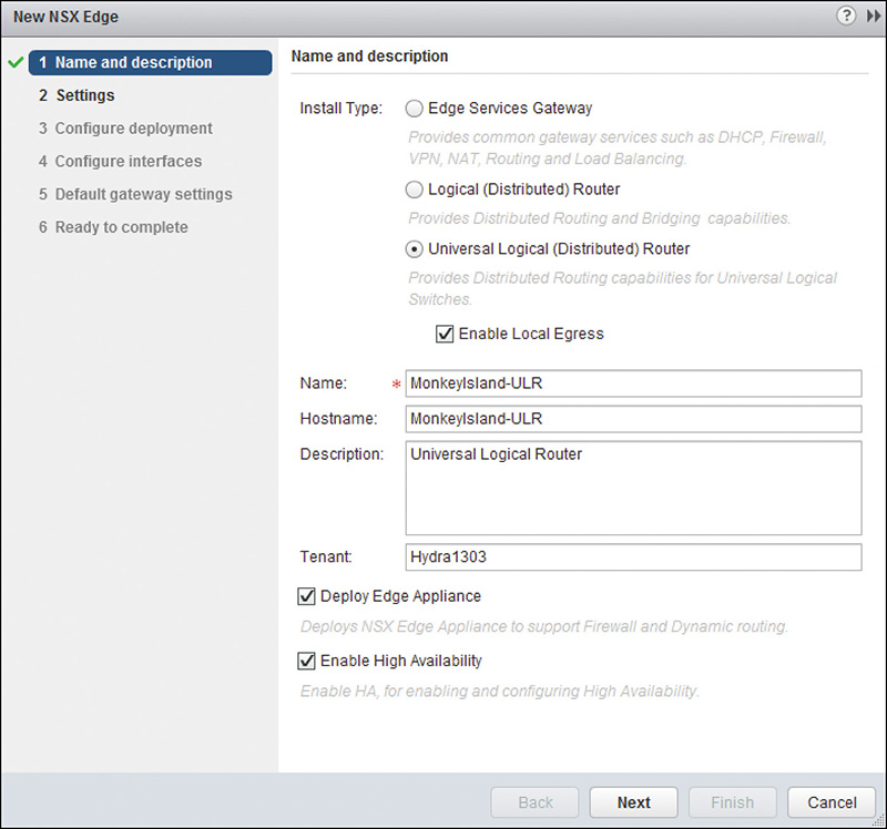
a. Install Type: Select whether to deploy an NSX Edge, a DLR, or a ULR. We select Universal Logical (Distributed) Router.
You will notice in step 6, the New NSX Edge wizard, Firewall and HA disappears.
You will also notice the box Enable Local Egress. This feature allows the ULR to send egress traffic to NSX Edges that are in the same location as the copy of the ULR sending the egress traffic. We learn about this feature later in this chapter when we learn about Locale ID.
b. Enter a name for the logical router.
This name will be used by vCenter to name the Control VM.
c. Optionally enter the hostname, a description, and a tenant name.
The Tenant field is used for management and naming of the logical routers. This field has no impact on the performance or functionality of the logical router.
d. Check the Deploy NSX Edge box if you want to deploy the Control VM.
If deploying an NSX Edge, this option allows you to configure the NSX Edge without actually deploying the appliance. This is handy for staging. If deploying a logical router, this option allows you to deploy the Control VM. Once the logical router is deployed, you can’t add the Control VM later.
e. Check the Enable High Availability box if you want to enable Edge HA.
This option deploys two NSX Edges or Control VMs, one in Active and one in Standby mode. Chapter 9 covers the NSX Edge HA feature in more detail.
f. After you have completed this step, it should look like Figure 7-5. Click Next to continue.
Step 5. In the Settings step, enter the administrator’s username and password, and click Next.
a. This credential is used when logging in, via SSH or the console, to the Control VM. The password must be 12 characters long containing:
At least one uppercase letter
At least one lowercase letter
At least one number
At least one special character, such as ! or $
b. You can enable SSH access to the Control VM here.
If you enable SSH access, the Control VM adds an internal Firewall rule allowing the SSH access.
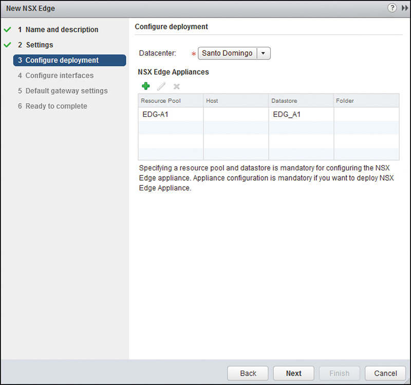
Step 6. In the Configure Deployment step, choose among the following options:
a. Datacenter: Select the data center where the Control VM will be deployed.
The data center options are for the vCenter paired with the NSX Manager from step 2.
b. NSX Edge Appliances: Select the resource pool or cluster and datastore where to deploy the Control VM. This is an optional field.
If configuring the logical router with NSX Edge HA, as mentioned in step 4e above, you can select where the second Control VM will be deployed.
c. After you complete this step, it should look similar to Figure 7-6. Click Next to continue.
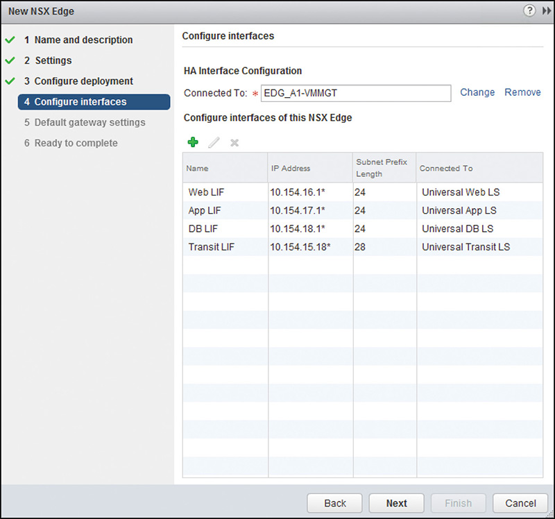
Step 7. In the Configure Interfaces step, you do two things. First, tell NSX Manager where to connect the Control VM’s HA interface. Second, tell NSX Manager the LIFs the logical router instance will have. You can always add, edit, and remove LIFs after the wizard is completed.
a. HA Interface Configuration: Select the dvPortgroup or logical switch the Control VM’s HA interface will connect to.
b. Configure Interfaces of this NSX Edge: These are the LIFs for the logical router. You can add up to 1,000 LIFs.
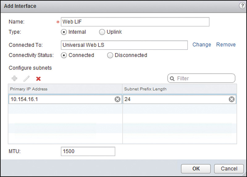
i. Clicking on the green + icon opens the Add Interface Wizard.
Give the LIF a name and assign it as an Internal or Uplink LIF.
Select the logical switch the ULR’s LIF will connect to. If this was for a DLR, you would have a choice to connect the LIF to a VLAN backed dvPortgroup.
ii. Add the IP address for each LIF.
Each LIF can be configured with multiple IPs.
iii. If you want the LIF to support MTU larger than the standard 1500 bytes, you can do so here.
The LIF MTU should match the MTU being used by the virtual machines in the same segment the LIF is connecting to.
iv. The LIF configurations should look as in Figure 7-7. Click OK.
c. After you complete step 7, the configuration should look similar to Figure 7-8. Click Next to continue.
Step 8. The Default Gateway Settings field allows you to enter the default gateway for the logical router and the outgoing LIF. This is optional and you can add a default gateway after deployment.
Step 9. In Ready to Complete, review your settings. You may go back to make any desired changes. Once you are satisfied click Finish.
After you click Finish, the following happens in the background:
a. The vSphere Web Client hands off the configuration to vCenter, which then passes it to NSX Manager.
b. NSX Manager reviews the configuration for any errors.
If NSX Manager finds any errors, an error message is displayed to the user in the vSphere Web Client.
c. If all checks out, NSX Manager hands the Control VM OVF to vCenter with instructions to deploy it per the configurations.
Remember that NSX Manager has an OVF for every type of NSX appliance that needs to be deployed.
d. Once the Control VM is powered on, vCenter notifies NSX Manager.
e. NSX Manager accesses the Control VM, finishes the configuration, and updates the Control VM about all the LIFs in the logical router and the NSX Controllers.
f. NSX Manager updates the NSX Controller with any relevant information, such as default gateway.
g. Once the Control VM has booted up, it communicates with the NSX Controller responsible for the logical router.
At this point the Control VM does not have a dynamic routing table to provide the NSX Controller since you have not yet configured a routing process such as BGP.
h. The NSX Controller determines which ESXi hosts need a copy of the logical router instance and pushes the logical router configuration, such as LIFs and IPs, as well as the routing table.
You can verify the logical router instance has been successfully deployed in a few ways.
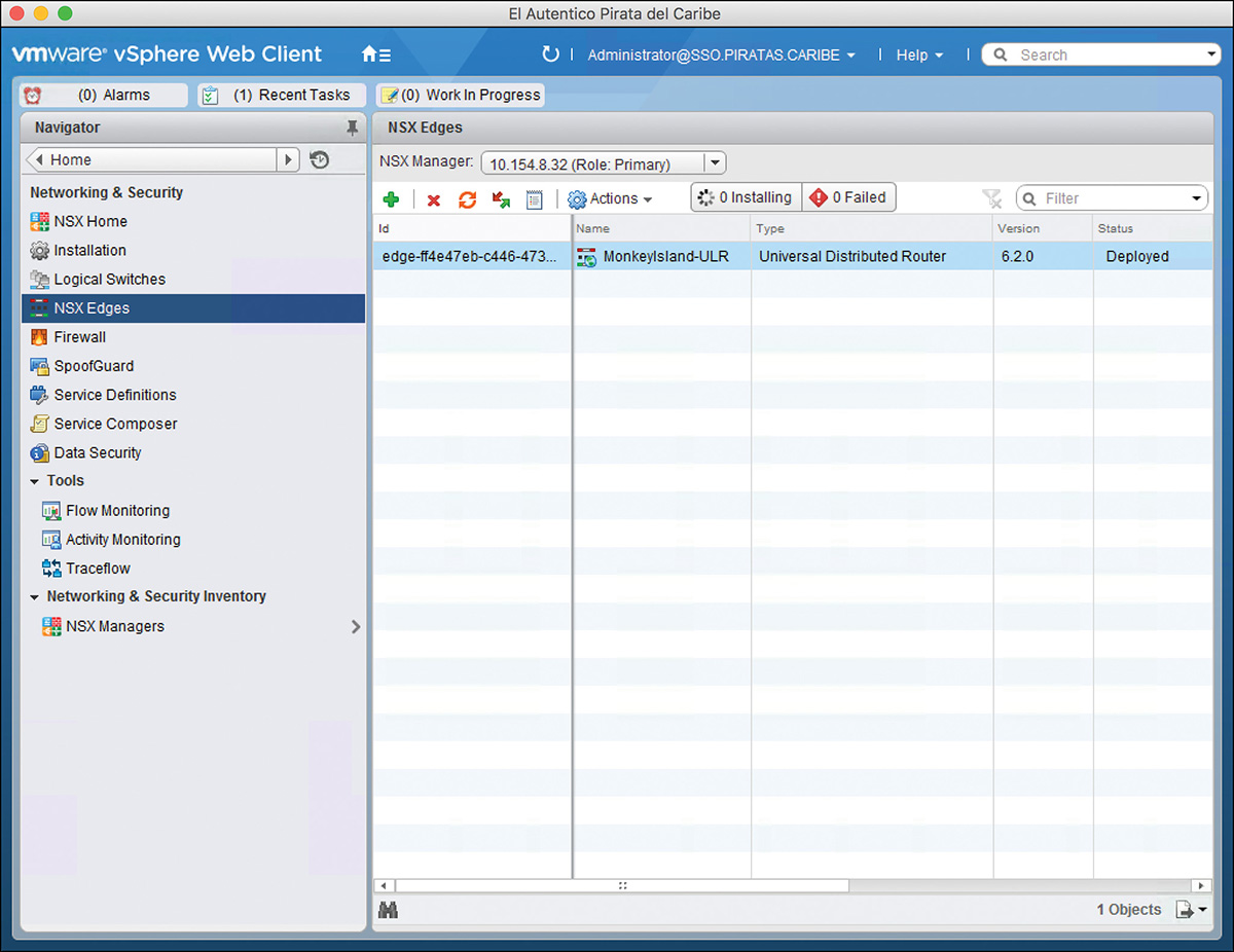
One way is to verify the logical router status directly from the NSX Edges view in the NSX Home page. Figure 7-9 shows the logical router instance has been created. Remember that a Control VM is simply a modified NSX Edge. From the NSX Edges view you can see both the logical router information and the NSX Edges.
The following fields can be inspected from this view:
Id: An NSX Manager provided tracking ID. It always starts with the word edge followed by a dash “-,” and a number. The ID is unique to each logical router and NSX Edge. For a DLR, the number starts at 1 and goes up. For a URL, the number is a UUID provided by NSX Manager.
Name: The name of the logical router assigned during installation. In vCenter, the Control VM’s name of a ULR will be the ID followed by this name.
Type: The type of router. In Figure 7-9 it states that this is a ULR. The other options for Type are NSX Edge and logical router (for a DLR).
Version: This version matches the version of the NSX Manager.
Status: The logical router can be Busy, Deployed, or Undeployed. If it states Undeployed it means the logical router configurations are saved in NSX Manager, but the actual Control VM has not been deployed by vCenter.
Tenant (to the right but not shown in Figure 7-9): This lists the name of the tenant you provided during configuration.
Interfaces (to the right but not shown in Figure 7-9): The number of interfaces configured in the logical router.
Size (to the right but not shown in Figure 7-9): The size of the Control VM. We review what the different size options are in Chapter 9.
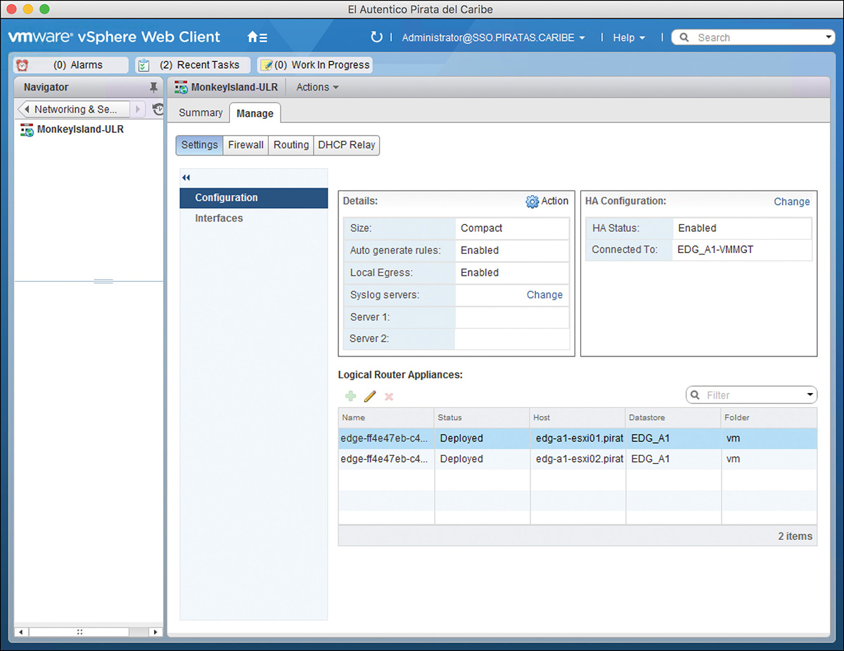
Double-clicking the logical router, from the Primary NSX Manager, opens the logical router Home view for the selected NSX Manager. Here you can verify additional configuration and some operation state of the logical router. Figure 7-10 shows the Manage > Settings > Configuration page. In this page, you can get a quick summary of the settings configured in the logical router and the number of Control VMs deployed by this NSX Manager and where they have been deployed. If the Control VM has not been deployed, you can deploy it here.
The ULR is visible from all NSX Managers in the same cross vCenter NSX domain. Earlier in the chapter, I mentioned that the ULR could have multiple Control VMs operating independently of each other. To add additional Control VMs, up to 8 total, go to the ULR Home page view from the Secondary NSX Manager you want to own the Control VM and add it from the Manage > Settings > Configuration page.
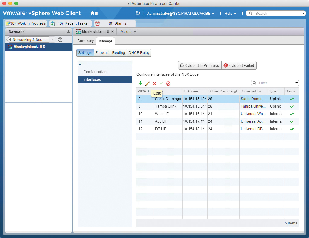
From the Interfaces page, as shown in Figure 7-11, you can see the LIFs, their IPs, the switch to which they connect, and their status. From here you can add new LIFs, edit the configuration of an existing LIF, disconnect it, or connect it. Only the Primary NSX Manager can make any changes to LIFs. The Secondary NSX Managers only have read-only access to the LIFs.
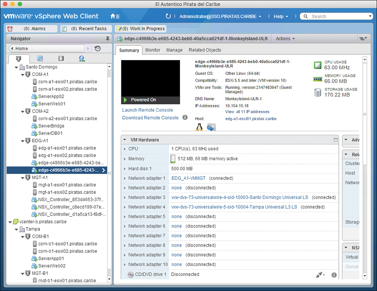
Another option to verify the status of the Control VM is to go to the Host and Clusters or VM and Templates views in the vCenter associated with the NSX Manager that deployed it and look for the Control VM. The name of the Control VM for a logical router matches the name you assigned it during installation followed by a number (0 or 1). The name of the Control VM for the ULR is the ULR ID followed by a number (0 or 1) followed by the ULR name. The number 0 means this is the first Control VM. If you have enabled Edge HA for the Control VM, the second Control VM has the same name as the first but with the number 1. Figure 7-12 shows the summary page of a Control VM after being deployed. In the figure you can see the following:
The number of vCPUs assigned to the Control VM, which is 1.
The amount of vRAM given to the Control VM, 512 MB.
The size of the HDD given to the Control VM, 500 MB.
The host where the Control VM is deployed.
In Figure 7-12, notice Network adapter 4 is connected to the uplink segment Universal Transit LS. This is where the uplink segment the ULR’s Uplink LIF Universal Transit is connected.
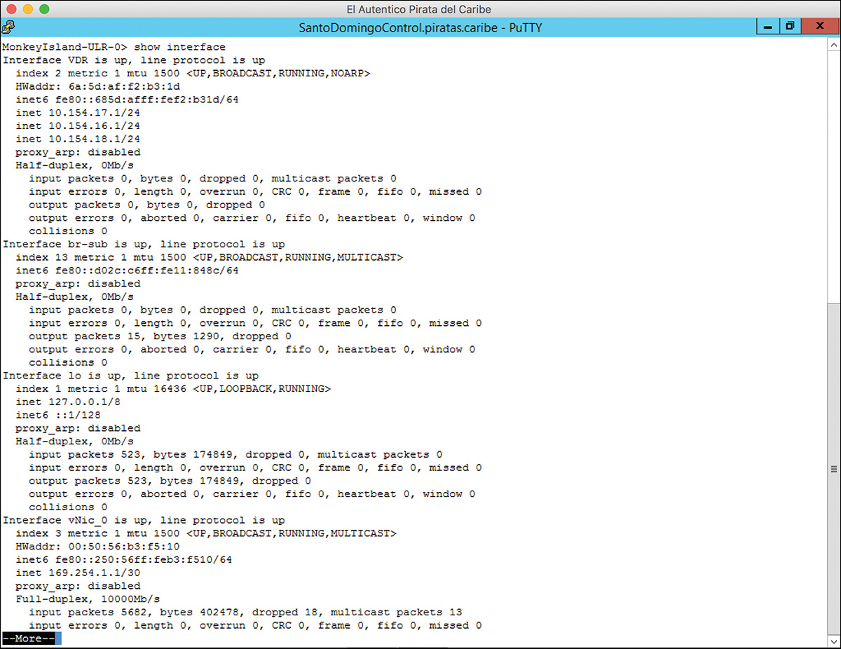
While in the Control VM Summary page, you can click Launch Remote Console to get CLI access to the Control VM. Optionally, if you have allowed SSH access to the Control VM, you can SSH to the Control VM to get the same CLI access. From the CLI you can execute commands to verify the configuration of the logical router. For example, as shown in Figure 7-13, you can execute the command show interface. The output shows all the Control VM interfaces, including the IP information per interface. Take a look at the first interface, Interface VDR, where VDR stands for Viva Dominican Republic (or is it virtual distributed router? I can’t seem to recall which one it is). That interface is the placeholder for the logical router interfaces, listing all the IPs configured in the logical router LIFs. You can also see the Control VM’s management interface, vNic_0. It includes the IP of the HA interface and the IP for the HA heartbeat since we have configured Edge HA. Remember that we expand on the HA heartbeat in Chapter 9. One more thing before we delve into Figure 7-13. Do you recognize the hostname of the Control VM? It is the hostname we gave it during the Name and Description step.
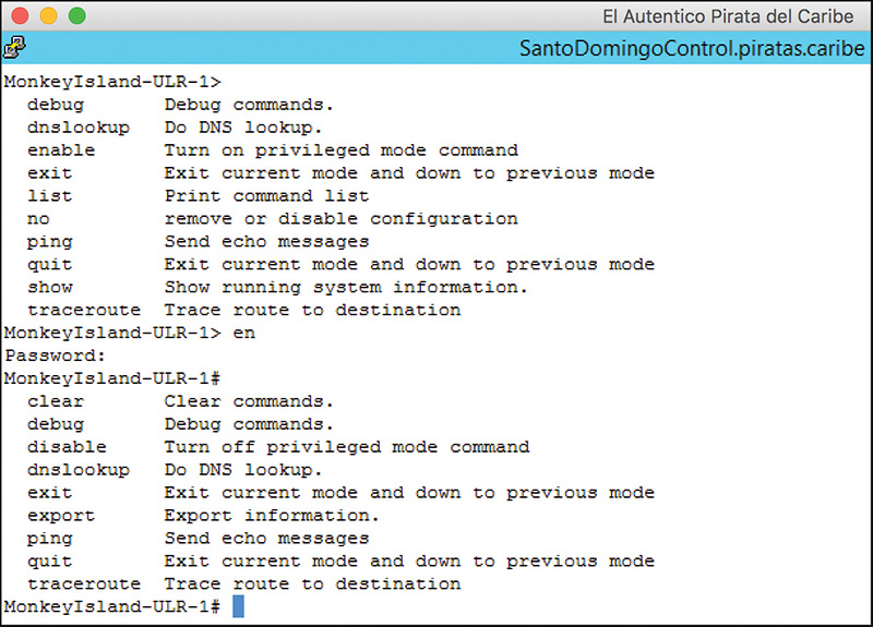
As a reminder, configuration changes can only be made via NSX Manager. You can’t make any configuration changes to the Control VM or the logical router instance from the CLI. Most commands are strictly for viewing current status, such as configuration and debugging. Figure 7-14 shows the available commands for the Control VM in user mode and privileged mode. As it is shown, there are no commands to make configuration changes.
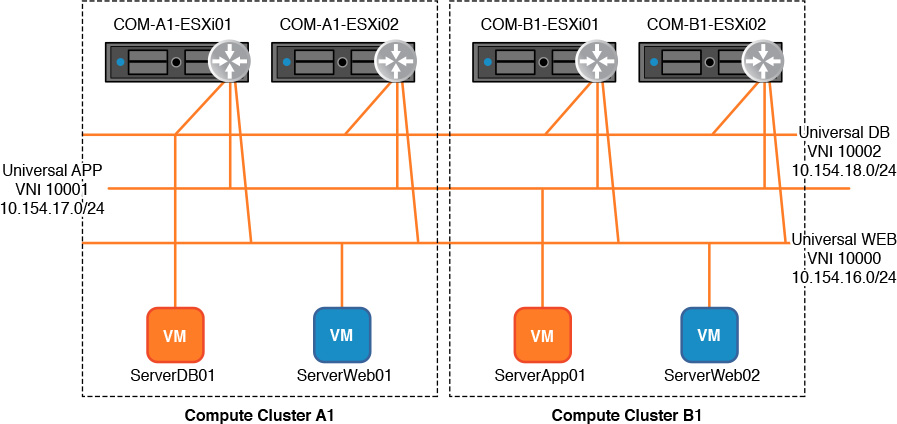
Let’s test our connectivity by doing some pings across some VMs. Figure 7-15 shows a logical diagram of our environment, which includes the ESXi hosts where each VM is running. The logical router has an LIF in each logical switch, and it is the default gateway for each VM. The default gateway of each segment is the 10.10.X.1 IP.
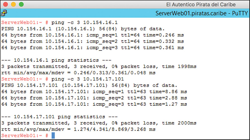
If our ULR is configured correctly, ServerDB01 should be able to ping its default gateway, 10.154.16.1, and ping any other virtual machine from the WebApp, such as ServerApp01. Figure 7-16 shows the results of the pings.
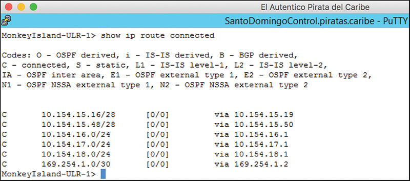
If we take a look at the MonkeyIsland-ULR Control VM, we can execute the command show IP route to see the routing table. As shown in Figure 7-17, the routing table only includes directly connected subnets and the default gateway we added during deployment of the logical router. In Chapter 12 we introduce routing protocols and see our routing table grow to include additional subnets.
If we go to the NSX Manager, we can determine which NSX Controller is responsible for our MonkeyIsland-ULR logical router, as shown in Figure 7-18. Figure 7-18 shows the output of the command show logical-router controller master dlr all brief (the NSX Controller equivalent command is show control-cluster logical-routers instance all). The fields shown are as follows:
LR-Id: Each logical router has a unique LR-ID.
LR-Name: NSX Manager assigns the logical router name. If the logical router was assigned a tenant, the tenant is part of the name. Otherwise, the word default is used.
Universal: If this is a URL or not.
Service-Controller: The NSX Controller responsible for the logical router.
Egress-Locale: If this logical router is doing local egress. All DLRs do local egress.
In-Sync: If the logical router is synchronized among the NSX Controller and the ESXi hosts.
Sync-Category: The category of the synchronization state.
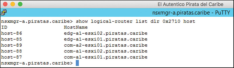
To see all the ESXi hosts that have a copy of the ULR, and their host-id, use the NSX Manager CLI command show logical-router list dlr dlr-id host. The equivalent NSX Controller command is show control-cluster logical-router connections router-id. Figure 7-19 shows the output of the command show logical-router list dlr 0x2710 host.
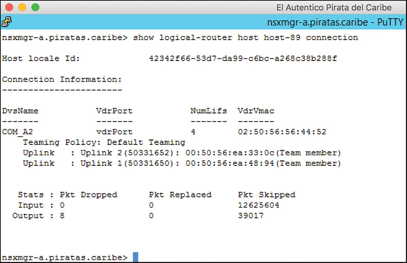
If we execute the command show logical-router host host-id connection, we can see some information regarding the ESXi host’s copies of the logical routers (the ESXi host CLI equivalent command is net-vdr -C -l). In Figure 7-20, we can see the output of the command using host-id host-89. The fields displayed by the command are as follows:
Host Locale Id: The Locale ID assigned to this ESXi host. More on Locale ID later in this chapter.
DvsName: The vDS used during host preparation.
VdrPort: The type of interface in the vDS used by the logical routers. All LIFs are assigned to a special interface in the vDS called vdrPort.
NumLifs: The number of VXLAN LIFs in this ESXi host.
VdrMAC: The vMAC.
Teaming Policy: The teaming policy selected during host preparation
Uplink: The uplinks, from the teaming policy, that are being used by NSX, the interface number, the pMAC assigned to each uplink, and if the uplink is participating in the teaming.
Yes, I said logical routers in plural. You should notice that there are only two pMACs in Figure 7-20, which tells us that all copies of logical routers running in the same ESXi hosts use the same pMACs. This is another reason you can’t connect two LIFs from different logical routers in the same logical switch.
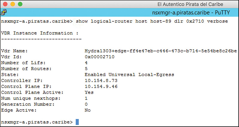
You can use the command show logical-router host host-id dlr dlr-id [brief | verbose] to see the status of the ULR in the ESXi host. The verbose version of this command is equivalent to the ESXi host CLI command net-vdr –I –l dlr-id. To get the brief version of the command, add --brief. Figure 7-21 shows the output of the command show logical-router host host-89 dlr 0x2710 verbose.
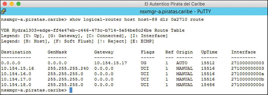
Finally, to see the routing table the ESXi host has for the logical router, issue the command show logical-router host host-id dlr dlr-id route, which is equivalent to the ESXi host CLI command net-vdr -l --route vdr-id, as shown in Figure 7-22.
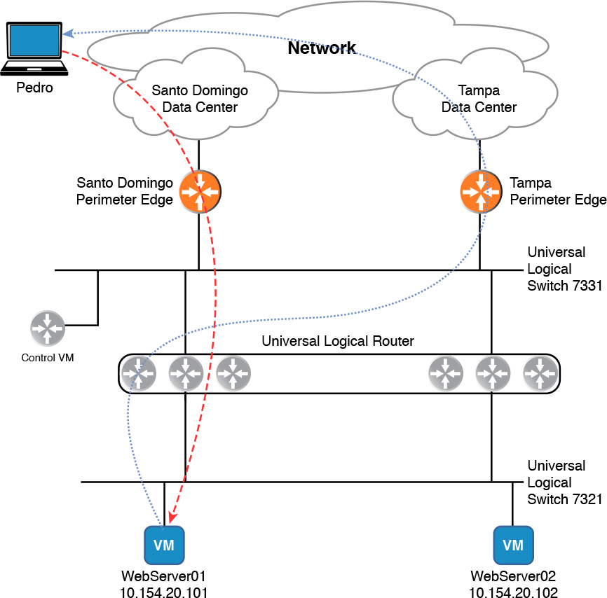
The universal logical router has one special feature not available to the distributed logical router. Before I explain the feature, have a look at Figure 7-23, which shows a ULR in two data centers. Virtual machine ServerWeb01 is in Data Center Santo Domingo, and ServerWeb02 is in Data Center Tampa.
Both the NSX Edge in Data Center Santo Domingo and the NSX Edge in Data Center Tampa are advertising the subnet of ServerWeb01 and ServerWeb02 to the physical world while advertising a default route to the ULR. A user in the city of Santo Domingo sends a web page request to ServerWeb01, which is routed via the Santo Domingo NSX Edge. The response from ServerWeb01 is received by the local copy of the ULR in Data Center Santo Domingo, which sees two default routes, one to each NSX Edge. About half the time the ULR forwards the traffic to the NSX Edge in the Tampa Data Center, which then sends the traffic over to the physical network in Tampa. If the user had requested the page from ServerWeb02, the reverse would be true.
This is an example of network tromboning. Network tromboning is defined as asymmetrical network traffic that does not use the best path to the destination, causing traffic to flow over nonoptimal paths. Network tromboning typically occurs when subnet location information is obfuscated by the stretching of Layer 2, such as when we use universal logical switches.
With Locale ID we can provide some locality information that is used by the ULR for egress traffic decisions, thus allowing for local egress. The Locale ID is a number in hex, 128 bits long, that is mutually shared by the Control VM and all ULR copies in the same location, such as a data center. When the Control VM sends routing table information to the NSX Controller responsible for the ULR, the NSX Controller only shares the route information with those ESXi hosts running copies of the ULR with the same Locale ID as the Control VM.
The NSX Controller does not use the Locale ID when it pushes routing updates to the ESXi hosts running copies of the DLR.
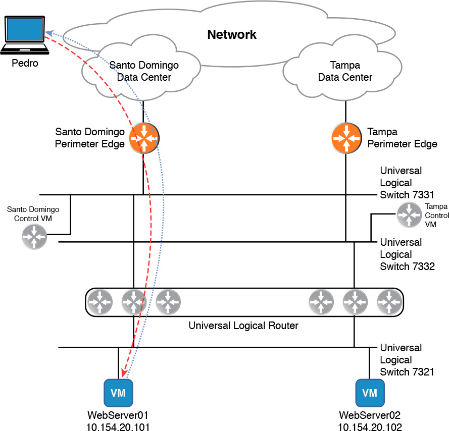
Do you recall that the ULR supports having multiple Control VMs? Have a look at Figure 7-24, which now has two Control VMs and the ULR has been configured for local egress. The Control VM in the Santo Domingo Data Center has the same Locale ID as the ESXi hosts in the Santo Domingo Data Center. The Control VM in the Tampa Data Center has the same Locale ID as the ESXi host in the Tampa Data Center.
The Control VM in Santo Domingo only exchanges routing information with the NSX Edge in Santo Domingo. The Control VM in Tampa only exchanges routing information with the NSX Edge in Tampa. Now when ServerWeb01 responds to the user, the ULR in Santo Domingo only knows of the routes advertised by the NSX Edge in Santo Domingo, thus it forwards all traffic to the NSX Edge in Santo Domingo.
All copies of the ULR, regardless of the Locale ID, have the same LIFs and directly connected subnets in the routing table.
By default, the Locale ID of the ULR is the UUID of the NSX Manager that deploys the Control VM. The Locale ID can be changed at the Control VM, the ESXi cluster, or individually at each ESXi host. To change the Locale ID at the Control VM, go to the NSX Edges view and select the Primary or Secondary NSX Manager that owns the Control VM, double-click on the ULR, and go to Manage > Routing > Global Configuration. Click Edit next to Routing Configuration, enter the 128-bit Hex Locale ID, and click OK. Don’t forget to publish the changes.
To change the Locale ID at the cluster or ESXi host level, go to Installation view > Host Preparation. To change the Locale ID for the cluster, click the cog in either the Installation Status, Firewall, or VXLAN columns and select Change Locale ID. This changes the Locale ID for all ESXi hosts in the cluster. To change the Locale ID for an ESXi host, select the cog in either of the three columns for the particular ESXi host that you want to make the change.
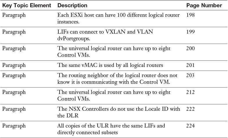
Review the most important topics from inside the chapter, noted with the Key Topic icon in the outer margin of the page. Table 7-2 lists these key topics and the page numbers where each is found.
Define the following key terms from this chapter, and check your answers in the Glossary: