Objective 5.3—Configure and Manage Layer 2 Bridging
This chapter covers all or part of the following VCP6-NV exam blueprint topics:
Objective 5.3—Configure and Manage Layer 2 Bridging
Objective 6.2—Configure and Manage Logical Virtual Private Networks (VPN)
Many applications have a network requirement of Layer 2 connectivity among tiers of the application. This requirement is easily met by extending a VLAN to the application tiers, but only if the tiers are within close physical proximity. You don’t need NSX to extend the VLANs in this situation. If the tiers are not within close physical proximity, it can be a challenge to extend the Ethernet broadcast domain. The problem can be more daunting if the application is partially virtualized.
NSX provides three ways to extend Ethernet broadcast domains to different tiers of an application. The first method is by using logical switches, which we covered in Chapter 5, “NSX Switches.” The other two methods are Layer 2 VPNs with the NSX Edge and Layer 2 Bridging with the distributed logical router (DLR). This chapter covers these two other methods and how to configure them.
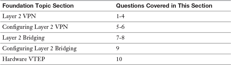
The “Do I Know This Already?” quiz allows you to assess whether you should read this entire chapter or simply jump to the “Exam Preparation Tasks” section for review. If you are in doubt, read the entire chapter. Table 10-1 outlines the major headings in this chapter and the corresponding “Do I Know This Already?” quiz questions. You can find the answers in Appendix A, “Answers to the ‘Do I Know This Already?’ Quizzes.”
1. How many concurrent Layer 2 VPN tunnels does a distributed logical router support?
a. 0
b. 1
c. 10
d. 16
2. What is the default port number used by NSX for Layer 2 VPN?
a. TCP 22
b. TCP 443
c. UDP 500
d. TCP 1723
3. Which two encryption algorithms are not supported in Layer 2 VPN? (Choose two.)
a. DES-CBC3
b. AES-128
c. 3DES
d. AES-192
4. Two NSX Edges form a Layer 2 VPN. Which encryption algorithm is used?
a. The encryption algorithm set on the first NSX Edge device that is configured
b. The encryption algorithm set on the Layer 2 VPN Server
c. The strongest encryption algorithm configured between the two NSX Edges as determined during tunnel negotiation
d. The weakest encryption algorithm configured between the two NSX Edges as determined during tunnel negotiation
5. How many interfaces are needed on an NSX Edge to configure a Layer 2 VPN?
a. One Uplink interface
b. Two Uplink interfaces
c. One Uplink interface and one Internal interface
d. One Internal interface
6. An NSX administrator has two available IPs, 10.154.17.10 and 10.154.17.11. The IPs are for use with the interfaces connecting to segments that will be extended via two NSX Edges using a Layer 2 VPN.
How must the IP addresses be configured on the interface of each NSX Edge?
a. The Layer 2 VPN Server must have the first IP in the range, 10.154.17.10.
b. Both NSX Edges must use the same IP.
c. Each NSX Edge can use either IP, but not the same IP.
d. The Layer 2 VPN Server is given both IPs and assigns them to the NSX Edges during tunnel negotiation.
7. Layer 2 Bridging supports which types of Ethernet extensions?
a. VXLAN-VXLAN
b. Layer 2 VPN
c. VLAN-VLAN
d. VLAN-VXLAN
8. What is the role of the Bridge Instance?
a. To coordinate the bridging among all the logical switches in the transport zone
b. To bridge between a logical switch and a VLAN
c. To provide a logical connection between two clusters in different transport zones
d. To back up the Layer 2 NSX Controller
9. Which of the following is not a requirement to configure Layer 2 Bridging?
a. A distributed logical router
b. An NSX Edge
c. A logical switch linked to the Control VM
d. A VLAN portgroup
10. In NSX 6.2, which NSX entity communicates with the hardware VTEP?
a. NSX Manager
b. NSX Controller
c. NSX Edge
d. Logical Router Control VM
The term Layer 2 VPN refers to mechanisms that can extend a Layer 2 domain, typically Ethernet, over an untrusted medium. The extension is normally done over a tunnel. Layer 2 VPNs have the capability of providing data security by using an encryption algorithm such as Data Encryption Standard (DES). Some sample uses of a Layer 2 VPN are as follows:
Extend a Layer 2 between a remote office and the main office.
Extend a Layer 2 between virtual machines in different data centers.
Extend a Layer 2 between a private and a public cloud.
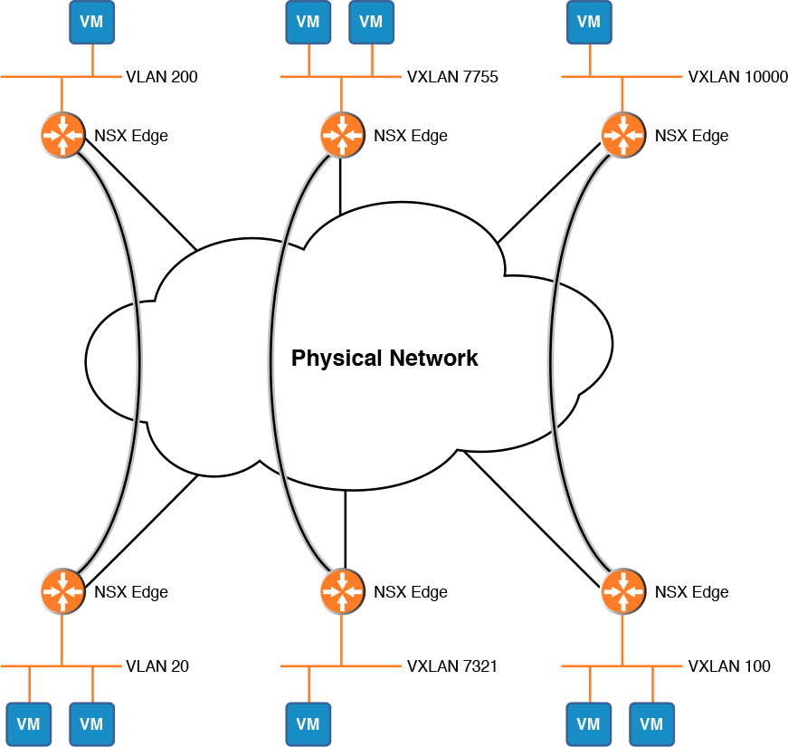
The NSX Edge supports Layer 2 VPN over Secure Sockets Layer (SSL), port TCP 443. If the NSX Edge is extending a VLAN, the VLAN must be configured in a distributed portgroup. Figure 10-1 shows a logical view of multiple pairs of NSX Edges creating a Layer 2 VPN between VXLANs, VLANs, and a VXLAN and a VLAN. If connecting to VLANs via Layer 2 VPN, the VLAN numbers can be different.
The NSX Edge can also be used to extend a VLAN between a private cloud and vCloud Hybrid Services, vCloud Air, as shown in Figure 10-2.

The NSX Edge supports Layer 2 VPN in a point-to-point deployment, and it must be with another NSX Edge in a server-client relationship. It does not matter which of the two Edges is the server as long as the other one is configured as the client. The NSX Edge can be used to extend a VLAN or VXLAN between two data centers even if the NSX Edges are managed by different NSX Managers or one of the Edges is a Standalone Edge.
If the NSX Edges are deployed in ESXi hosts with processors that support Advance Encryption Standard New Instructions (AES-NI), the NSX Edge can send up to 2 Gbps through the Layer 2 VPN tunnel. Of course, if the bandwidth in the path between the two Edges is less than 2 Gbps, the throughput would be less.
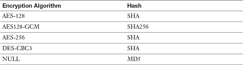
Table 10-2 shows the encryption algorithms supported by the NSX Edge for Layer 2 VPN. The Layer 2 VPN Server dictates the encryption algorithm upon tunnel negotiations with the Layer 2 VPN Client.
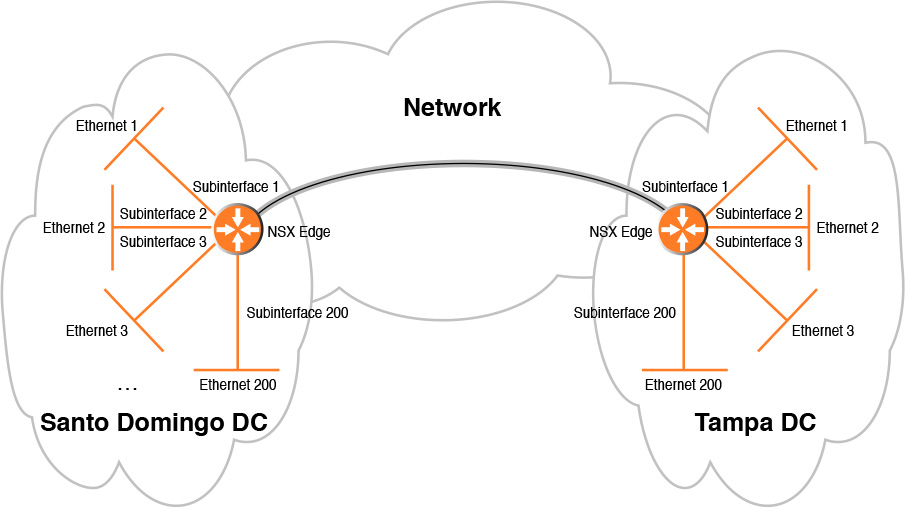
An NSX Edge can only support being either a client or a server at one time, but not both, and requires a Trunk interface with subinterfaces. A pair of Edges can only do a Layer 2 VPN for 200 pairs of Ethernet domains, as shown in Figure 10-3. The path from the Layer 2 VPN Server and the Layer 2 VPN Client must have an MTU of 1600 or higher.
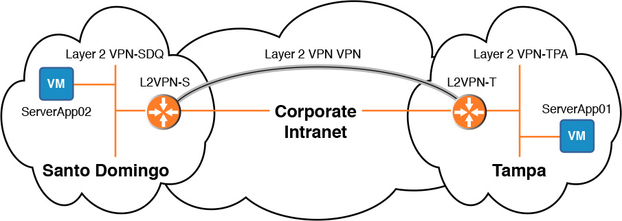
To configure a Layer 2 VPN, you must already have two deployed Edges, each one with an Internal interface connected to the Layer 2 segment that will be extended and an Uplink interface to be the tunnel endpoint. Figure 10-4 shows two NSX Edges, L2VPN-S and L2VPN-T, and two virtual machines, ServerApp01 and ServerApp02, in their respective data centers, Santo Domingo and Tampa.
We spend this section configuring a Layer 2 VPN between the two Edges in Figure 10-3. We assign L2VPN-T as the Layer 2 VPN Server and L2VPN-S as the Layer 2 VPN client. Figure 10-5 shows the logical diagram of how our Layer 2 VPN will look once we have completed our configuration.
Table 10-3 shows the IP configuration and Layer 2 connectivity for the NSX Edges and the virtual machines. Virtual Machine ServerApp01 is connected to logical switch Layer 2 VPN – TPA, and Virtual Machine ServerApp02 is connected to logical switch Layer 2 VPN – SDQ.
In Table 10-3 you should notice that both Edges have different IPs in the Layer 2 segment that will be extended. This is a VMware requirement for Layer 2 VPN.
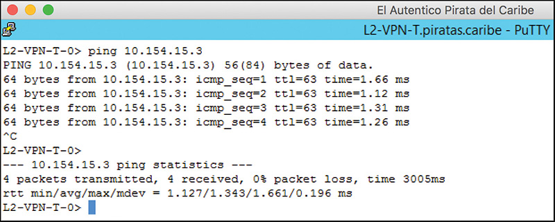
One thing that is implied but still worth mentioning: Edge L2VPN-S’s interface External-SDQ must have network reachability to Edge L2VPN-T’s interface External-TPA. Figure 10-6 shows a ping from L2-VPN-T’s External-TPA interface to L2-VPN-S’s External-SDQ interface.
Figure 10-7 shows the result of a ping from Virtual Machine ServerApp01 toward ServerApp02. The ping fails since we have not configured the Layer 2 VPN yet.
We are ready to start configuring a Layer 2 VPN. It does not matter which Edge we configure first, but it is not a bad idea to start with the server, so we start with the configuration of L2-VPN-T—the Layer 2 VPN Server.
Step 1. From the NSX Edges view, double-click the L2-VPN-T Edge.
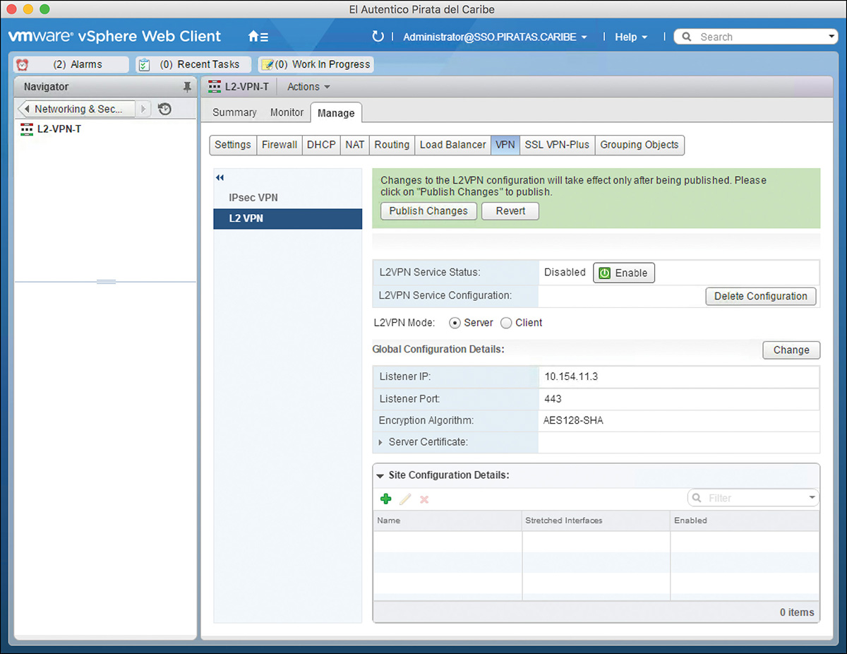
Step 2. Go to Manage > VPN and select the L2 VPN view.
Step 3. Select the dial next to Server and click Change.
Step 4. In Server Details enter the following configuration:
a. Listener IP: 10.154.11.3
This is the IP over which the Layer 2 VPN tunnels will travel, and it must belong to an Uplink interface. The incoming request from the Layer 2 VPN client to form a Layer 2 VPN needs to arrive over this interface.
b. Listener Port: 443.
The SSL port number is 443. Unless you have reasons to change it, leave the default. If you do change the port number, you must also change it at the Layer 2 VPN Client.
c. Encryption Algorithm: Select one of the options available:
AES128-SHA
AES128-GCM-SHA256
AES256-SHA
DEC-CBC3-SHA
NULL-MD5
Step 5. If the Edge has any certificates they will be listed in the Server Certificate table, and you can select one for the Layer 2 VPN. If the Edge does not have any certificates or you don’t want to use them, check the box Use System Generated Certificate (we cover how to add certificates to the Edge in Chapter 14, “NSX Edge Network Services and Security”).
Step 6. Your configuration should look similar to Figure 10-8. Click OK.
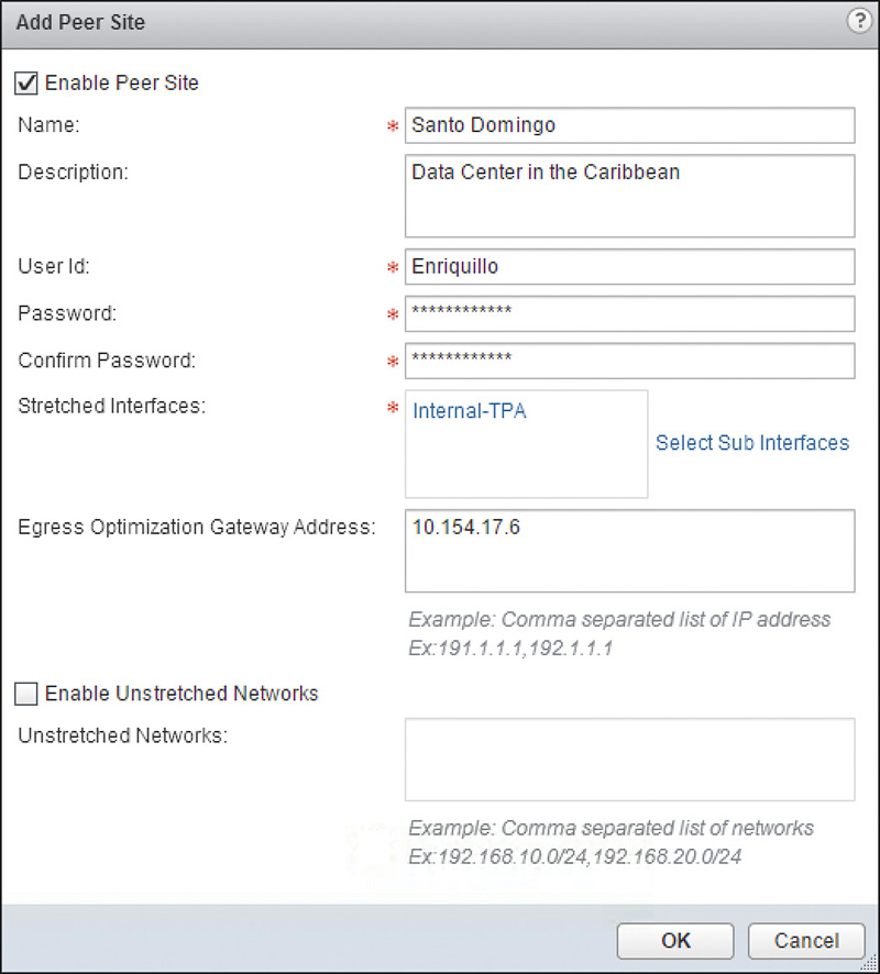
Step 7. In Site Configuration Details, click the green add icon and enter the following configuration:
Enable Peer Site: Check the box if you want to allow this Peer Site to establish an L2 VPN connection with this L2 VPN Server.
Name: Santo Domingo.
Description: Data Center in the Caribbean.
User Id: Any username you want. It must match the username configured at the Layer 2 VPN Client.
Password: Enter any password and retype in the next field.
Stretched Interfaces: Click the Select Sub Interfaces link to add all subinterfaces you want to stretch to this L2 VPN peer site. We will be adding the Internal – TPA subinterface.
This is where the Tunnel ID of the subinterface comes into play. When the L2 VPN Client for this Peer site we are configuring connects to this L2 VPN Server, the Tunnel ID is used to match the subinterfaces on both sides that belong to the same Layer 2 domain.
Egress Optimization Gateway Address: List all IPs for which this L2 VPN Server responds to ARP requests.
This is a long way to say default gateway, but in the form of a Virtual IP (VIP). Traffic received by the VIP is routed by this Edge and not sent over the L2 VPN tunnel. This VIP should match on the L2 VPN Client side.
Enable Upstretched Networks: Check the box and list any subnets that will not be sent over the L2 VPN tunnel.
Step 8. Your configuration should look like the one in Figure 10-9. Click OK if you are satisfied with the configuration.
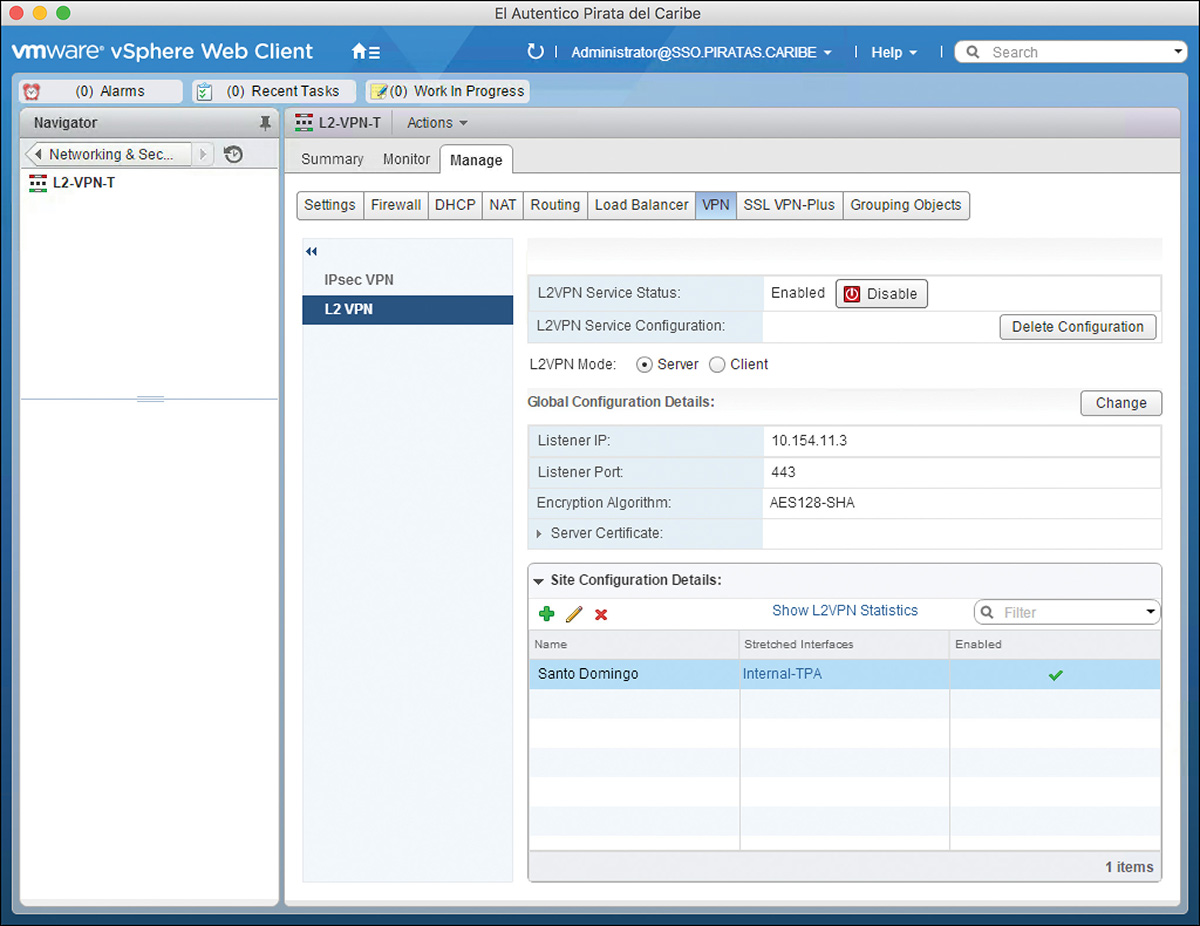
Step 9. Click the Enabled box, click Publish Changes, and you are done, as shown in Figure 10-10. This Edge is now listening for a client request from the peer sites to start a Layer 2 VPN.
The Enabled box turns to Disable.
Let’s configure the next Edge—L2-VPN-S—the one that acts as the Layer 2 VPN Client.
Step 1. Return to the NSX Edges view and double-click the L2-VPN-S Edge.
Step 2. Go to Manage > VPN and select the L2 VPN view.
Step 3. Select the dial next to Client and click Change.
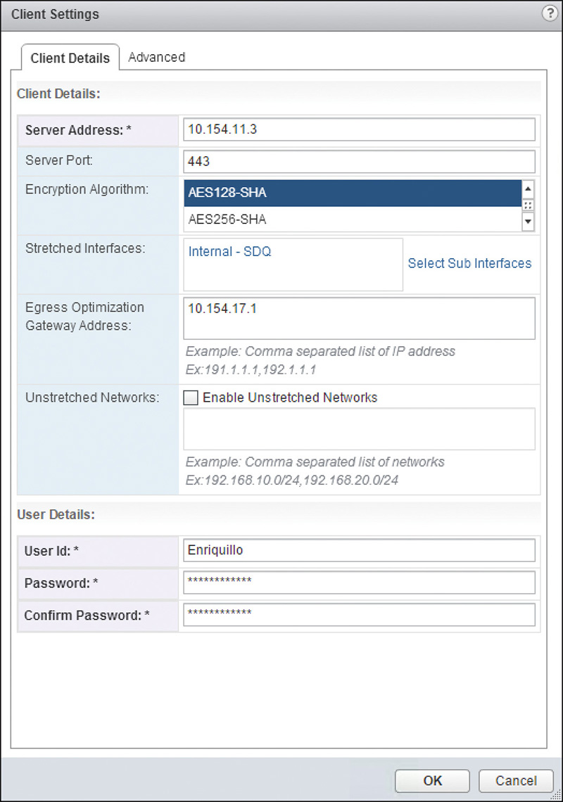
Step 4. In the Client Details tab, enter the following configuration:
a. Server Address: 10.154.11.3. This is the IP of the Layer 2 VPN Server.
b. Server Port: 443. Unless you have configured a different SSL port number at the Layer 2 VPN Server, leave this at the default value of 443.
c. Stretched Interfaces: Click the Select Sub Interfaces link to add all subinterfaces you want to stretch to this L2 VPN peer site. We will add the Internal – SDQ subinterface.
d. Egress Optimization Gateway Address: List all IPs for which this L2 VPN Client will respond to ARP requests.
e. Enable Upstretched Networks: Check the box and list any subnets that will not be sent over the L2 VPN tunnel.
Step 5. In User Details enter the following configuration:
a. User ID: Any username you want. It must match the username configured at the Layer 2 VPN Server.
b. Password: Enter the password configured in the Layer 2 VPN Server and retype it.
The configuration should look similar to Figure 10-11.
Step 6. In the Advanced tab’s Proxy Settings enter the following configuration if you want to use a proxy:
a. Enable Secure Proxy: Check the box to enable the proxy.
b. Address: The address of the proxy server.
c. Port: The port number for the proxy server.
d. User Name and Password: The credentials to have the Layer 2 VPN Client authenticate with the proxy server.
Step 7. If the Layer 2 VPN Server has any CA certificates and you want to have the Layer 2 VPN Client validate them, check the box Validate Server Certificate, select the certificate to validate from the certificate table, and click OK.
You would have to add the certificate in the Layer 2 VPN Client to use this feature. We cover certificates in Chapter 14.
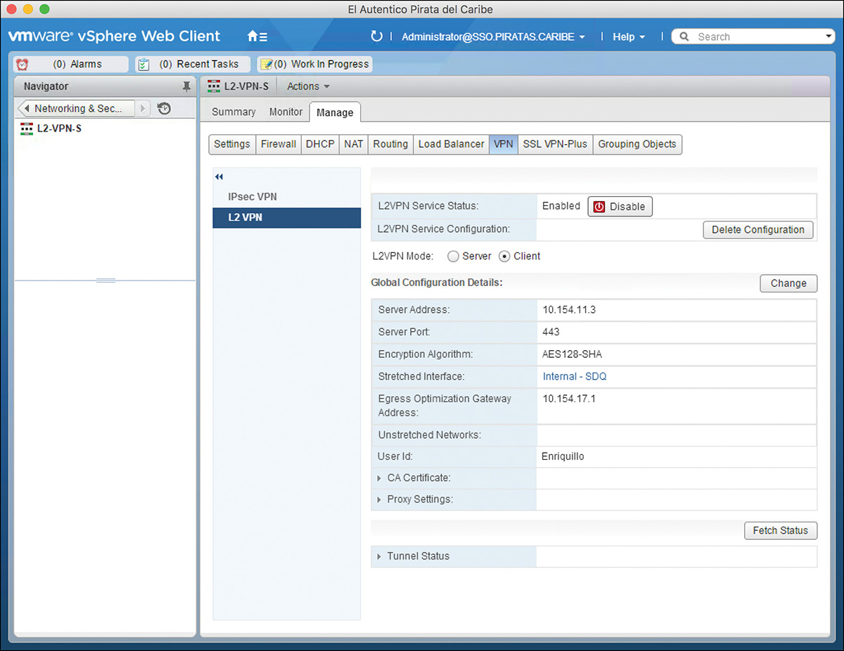
Step 8. Click the box Enabled and then click Publish Changes. Things should look as in Figure 10-12. This Edge is now trying to contact the Layer 2 VPN Server.
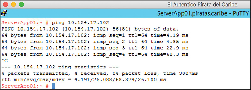
The best way to verify that your Layer 2 VPN is working is to send traffic, like a ping, across the tunnel. Figure 10-13 shows the ping test from Virtual Machine ServerApp01 toward ServerApp02. The ping is successful this time, meaning our tunnel is working.
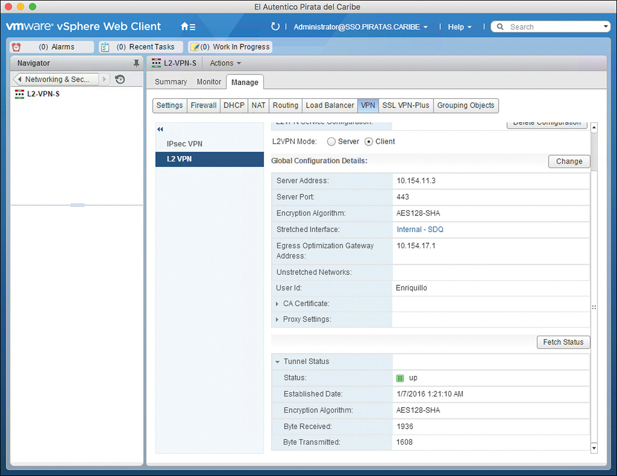
Another way to verify the tunnel status is to check the tunnel status in both the client and server sides. Figure 10-14 shows the tunnel status client sides. To show the status, click the Fetch Status button.
Figure 10-15 shows Figure 10-3 with the management plane entities and NSX Controllers added. We use Figure 10-15 to do a packet walk of the first ping sent from Virtual Machine ServerApp02 to ServerApp01.
We make the following assumptions for this packet walk:
Each data center has its own vCenter and NSX Manager.
Virtual Machine ServerApp01 is running in COM-B1-ESXi02.
Virtual Machine ServerApp02 is running in COM-A1-ESXi02.
NSX Edge L2-VPN-S is running in EDG-A1-ESXi02.
NSX Edge L2-VPN-T is running in COM-B1ESXi01.
ServerApp01 does not have an ARP entry for ServerApp02.
ServerApp02 does not have an ARP entry for ServerApp01.
Replication Mode for all logical switches is Hybrid or Unicast.
The NSX Controllers do not have an ARP entry for ServerApp01 or ServerApp02.
Step 1. ServerApp02 wants to send a ping to ServerApp01 but does not have an ARP entry for it.
Step 2. ServerApp02 sends an ARP request.
Step 3. Logical switch Layer 2 VPN – SDQ receives the request and processes it.
We covered in Chapter 6, “Logical Switch Packet Walks,” how ARP requests are handled by logical switches.
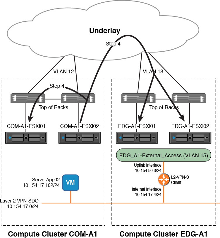
Step 4. Logical switch Layer 2 VPN – SDQ replicates the ARP request, as shown in Figure 10-16.
The number of VXLAN tunnels created depends on the Replication Mode configured.
Step 5. The ARP request is received by Edge L2-VPN-S’ Internal interface, Internal-SDQ.
The local copy of Layer 2 VPN – SDQ in ESXi host EDG-A1-ESXi02 learns the MAC address of ServerApp02.
Step 6. L2-VPN-S takes the ARP request, puts it in a Layer 2 VPN tunnel, and sends it to Edge L2-VPN-T.
The tunnel goes out of the Uplink interface External-SDQ, toward the physical network.
Step 7. Edge L2-VPN-T receives the tunnel traffic, over its Uplink Interface External-TPA, validates it, and decapsulates it.
Step 8. Edge L2-VPN-T takes the ARP request and sends it to logical switch Layer 2 VPN – TPA.
The traffic is sent out over the Internal interface, Internal-TPA.
Step 9. Logical switch Layer 2 VPN – TPA learns the MAC address of ServerApp02 and tells the NSX Controller.
If this had been a distributed portgroup instead of a logical switch, no MAC learning would’ve taken place.
Step 10. Logical switch Layer 2 VPN – TPA receives the ARP request and processes it.
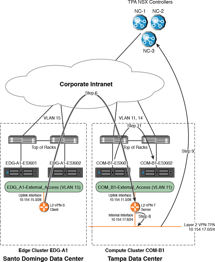
Step 11. Logical switch Layer 2 VPN – TPA replicates the ARP request, as shown in Figure 10-17.
The replication happens over VXLAN overlays.
Step 12. ServerApp01 receives the ARP request and processes it.
The local copy of Layer 2 VPN – TPA in ESXi host COM-A1-ESXi02 learns the MAC address of ServerApp02.
Step 13. ServerApp01 sends a unicast ARP reply to ServerApp02.
Step 14. Logical switch Layer 2 VPN – TPA receives the ARP reply, processes it, and sends it over to COM-B1ESXi01 over a unicast VXLAN overlay.
The logical switch learned the MAC address of ServerApp02 in step 12.
We covered how ARP replies are handled in Chapter 6.
Step 15. Logical switch Layer 2 VPN – TPA in COM-B1ESXi01 receives the ARP reply, processes it, and sends it to Edge L2-VPN-T’s interface Internal-TPA.
a. The logical switch learns ServerApp01’s MAC address.
b. The logical switch learned ServerApp02’s MAC address in step 10.
Step 16. Edge L2-VPN-T receives the ARP reply, puts it in a Layer 2 VPN tunnel, and sends it to Edge L2-VPN-S.
The tunnel goes out of the Uplink interface External-TPA, toward the physical network.
Step 17. Edge L2-VPN-S receives the tunnel traffic over its Uplink Interface External-SDQ, validates it, and decapsulates it.
Step 18. Edge L2-VPN-S takes the ARP reply and sends it to logical switch Layer 2 VPN – SDQ.
The traffic is sent out over the Internal interface, Internal-SDQ.
Step 19. Logical switch Layer 2 VPN – SDQ learns the MAC address of ServerApp01 and tells the NSX Controller.
Step 20. Logical switch Layer 2 VPN – SDQ receives the ARP reply and processes it.
Step 21. Logical switch Layer 2 VPN – SDQ forwards the ARP request in a VXLAN overlay unicast to COM-B1-ESXi02.
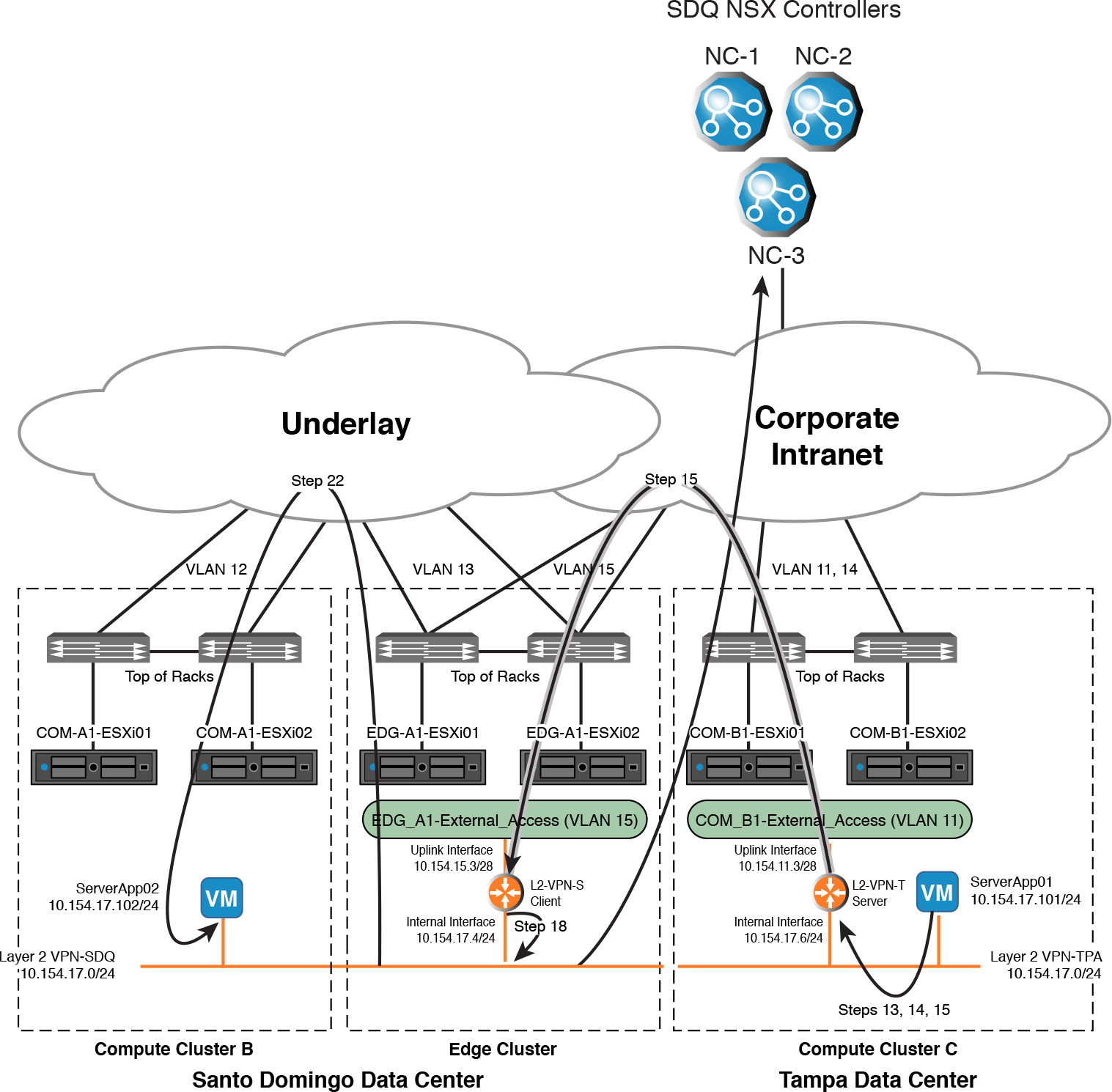
Step 22. ServerApp02 receives the ARP reply, adds the entry to its ARP table, and sends the first ping to L2-T-MV2, as shown in Figure 10-18.
Step 23. ServerApp01 receives the ping, but it doesn’t have an ARP entry in its ARP table for ServerApp02, so it sends out an ARP request for ServerApp02’s MAC.
Steps 1 thru 22 are repeated without the MAC learning by the logical switches.
This is a simple packet walk that has a lot of details (and many more that were left out because they were already covered in other chapters). As we continue our studying for the VCP6-NV exam you should expect some concepts to be a bit more involved as they will leverage a lot of the previous topics that we have already learned.
With Layer 2 VPNs we can extend Ethernet broadcast domains, whether VXLAN, VLANs, or both, over untrusted mediums. We can also extend the broadcast domain by bridging between virtual workloads, VXLAN, and physical workloads, VLAN. NSX does not provide an option to bridge between a virtual workload in a VXLAN and a physical workload in a VLAN. NSX does not support connecting a physical workload directly to a VXLAN (only VMs can be in an NSX VNI); therefore there is no option to bridge two VXLANs.
If a VM resides in the VLAN that is being bridged, that VM shares the same broadcast domain with the virtual workloads in the bridged logical switch.
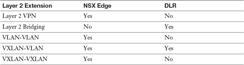
In NSX, the bridging of virtual and physical workloads is called Layer 2 Bridging. Layer 2 Bridging is done by the DLR, and it only supports bridging between VXLANs and VLANs. The ULR does not support Layer 2 Bridging. Table 10-4 shows the type of Layer 2 extensions supported by the NSX Edge and the DLR.
A typical use case for Layer 2 Bridging is for a mostly virtualized application. For example, an application has some or most of its tiers virtualized with the rest of the tiers continuing to run bare metal. The application has Layer 2 dependencies between some of the virtualized tiers and the physical tiers. Another use case is for physical to virtual migrations where the client does not want to change the IP of the application.
Layer 2 Bridging is done by selecting a logical switch and a distributed portgroup and telling a DLR to connect to each. These connections are LIFs but with connections to dvPorts in the vDS called sinkports. Remember that sinkports are special vDS ports that get a copy of all BUMs in the VLAN. Now, I know what you may be thinking “why is a router doing bridging?” It turns out that routers have been used as an inexpensive and quick way to do bridging for a long time. With the DLR, NSX is just honoring that tradition  .
.
You may connect a second LIF to the logical switch used for bridging and assign it an IP. This allows the DLR to be the default gateway for workloads connected to the logical switch or VLAN being bridged. Alternatively, workloads connecting to bridged segments may use an NSX Edge or a physical router as their default gateway. If the bridged LIF is not configured with an IP, the traffic in the bridge segment is kept completely isolated by the DLR doing Layer 2 Bridging from its other LIFs.
The function of Layer 2 Bridging is done in kernel, but it is not distributed. One of the ESXi hosts that has the DLR is selected to do all the bridging. That ESXi host is referred to as the Bridge Instance. The Bridge Instance is the only ESXi host that has the sinkport connections doing the bridging. None of the other ESXi hosts have the sinkport connections. This is the second setting (the pMAC being the first) where the copies of the DLR instances are not identical in each ESXi host. The Bridge Instance still does MAC learning and updates the NSX Controller responsible for the DLR. All MAC addresses learned by the Bridge Instance have a timer of 300 seconds, after which the entry is removed from the MAC table.
Figure 10-19 shows a DLR doing bridging between a VM in logical switch Santo Domingo Layer 2 Bridge and a physical server in VLAN 20.
The NSX Controller responsible for the DLR elects the ESXi host that will be the Bridge Instance. The selection is straightforward: Wherever the DLR Control VM is running, that ESXi host becomes the Bridge Instance. Thus you have control of which ESXi host becomes the Bridge Instance by choosing where the DLR Control VM runs. The NSX Controller provides a copy of the MAC table to the new Bridge Instance.
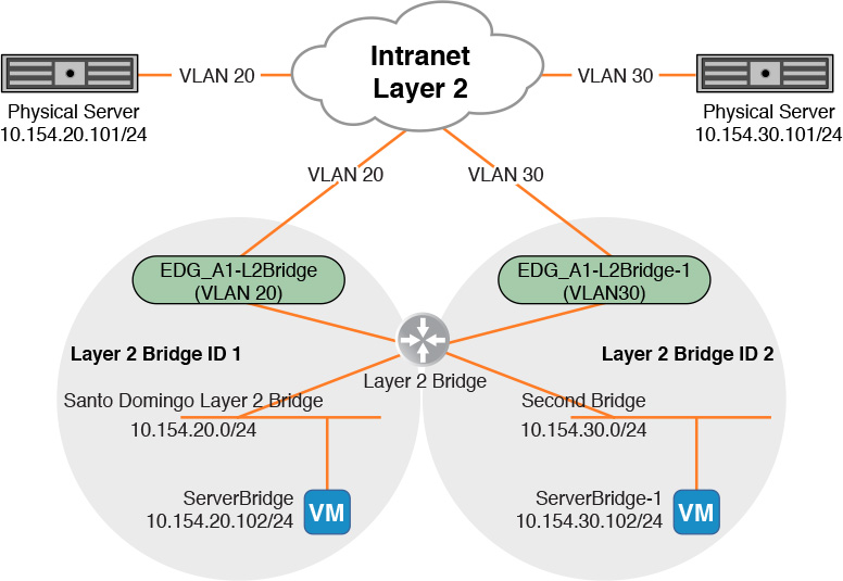
A single DLR can have multiple bridges as long as it always involves different pairs of VXLAN-VLAN LIFs; however, a DLR always has a single Bridge Instance. Multiple DLRs can be configured to do Layer 2 Bridging in different VXLAN-VLAN pairs. If you require having multiple Bridge Instances, you must deploy multiple DLRs to do Layer 2 Bridging. Figure 10-20 shows a single DLR doing Layer 2 Bridging for two different VXLAN-VLAN pairs. Traffic from one bridge pair is not seen by the other unless it is routed.
In the event that the ESXi host that is the Bridge Instance fails, a new Bridge Instance is selected. The selection follows the placement of the DLR Control VM, with the new ESXi host that runs the DLR Control VM becoming the new Bridge Instance. This implies that the VLAN that is being bridged must be presented to all ESXi hosts in the cluster(s) that might run the DLR Control VM. To be more specific, the same distributed portgroup that the VLAN LIF connects to must be present in all ESXi hosts that might run the Control VM.
All ESXi hosts in the cluster(s) where the Control VM might run must be part of the same vDS because they all need access to the same portgroup with the VLAN being bridged. Although you can configure the same VLAN in different portgroups in different distributed switches, vCenter does not support the same portgroup to exist in more than one vDS. Figure 10-21 shows a configuration with the Control VM restricted to the edge cluster and the DLR doing Layer 2 Bridging between the logical switch Santo Domingo Layer 2 Bridge and portgroup EDG_A1_L2Bridge.
The logical switch being bridged must belong to a transport zone that includes the Bridge Instance and all the ESXi hosts in the cluster where the DLR Control VM is.
Configuring Layer 2 Bridging is straightforward. First let’s go over the prerequisites:
A logical switch in a transport zone that includes the cluster(s) where the Control VM may run
A DLR
A VLAN portgroup in a vDS that has as members all the ESXi hosts from the cluster(s) where the Control VM may run
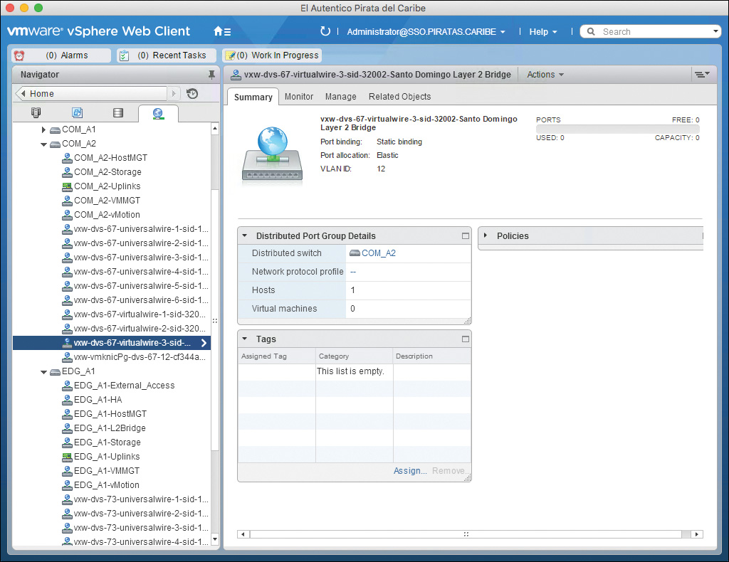
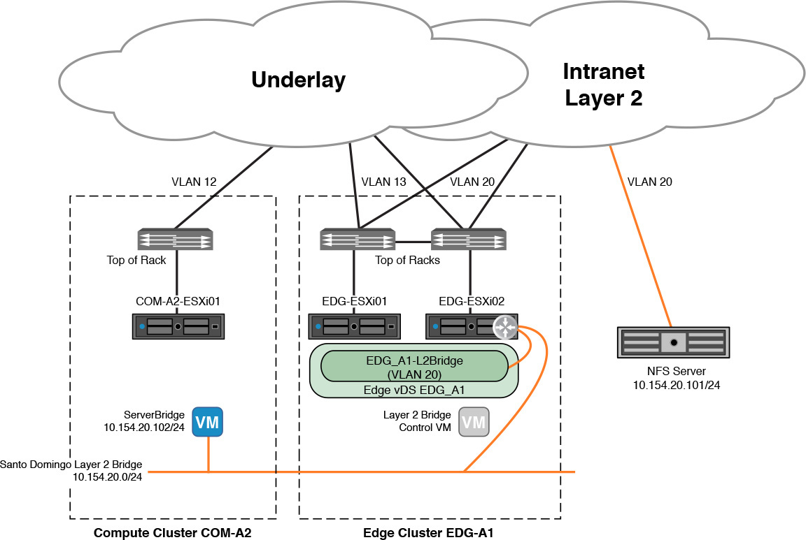
Figure 10-22 shows the logical switch Santo Domingo Layer 2 Bridge and a dvPortgroup EDG_A1_L2Bridge in vDS EDG_A1. Virtual Machine ServerBridge, not shown in Figure 10-22, is connected to logical switch Virtual Workload. The IP of ServerBridge is 10.154.20.102. For the DLR, we use DLR Layer 2 Bridge, acting as the default gateway with an IP of 10.154.20.1. An NFS share, with an IP of 10.154.20.101, is the physical entity.
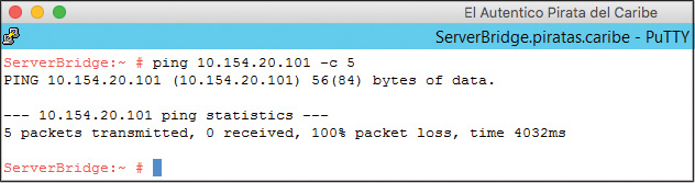
Before we start the configuration, let’s validate that there is no connectivity between Virtual Machine ServerBridge and the physical NFS server. Figure 10-23 shows the failed pings.
Step 1. From the NSX Edges view double-click the DLR Layer 2 Bridge.
Step 2. Go to Manage > Bridging.
Step 3. Click the green + icon.
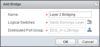
Step 4. In the Add Bridge Wizard, enter the following information:
a. Name: Assign the bridge a name.
b. Logical Switches: Select the logical switch where the virtual workload is connected.
c. Distributed Virtual Port Group: Select a portgroup that has the VLAN that will be bridged.
d. Your configuration should look similar to the one in Figure 10-24. Click OK.
Step 5. Click Publish.
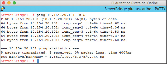
Just as with Layer 2 VPN, the best test you can do to verify that the Layer 2 Bridge is operational is to send traffic between the two sides. Figure 10-25 shows a successful ping from ServerBridge to the physical NFS server.
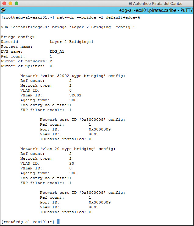
From the Bridge Instance we can run the command net-vdr --bridge -l vdrName to see the bridge configuration, as shown in Figure 10-26. The number 78798132 after the VDR name is the VDR ID.
In the Bridge Instance, we can also run the command net-vdr --bridge --mac-address-table vdrName to show the MAC table for the Layer 2 Bridge, as shown in Figure 10-27. The additional MAC addresses seen in the VLAN are a default gateway in the VLAN side and the MAC from which the Putty session was initiated.
Figure 10-27 Output of command net-vdr --bridge --mac-address-table default+edge-4 in the Bridge Instance
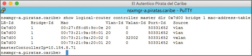
From the NSX Manger we can run the command show logical-router controller master dlr vdr-id bridge bridge-id mac-address-table (in the NSX Controller responsible for the DLR, we can run the related command show control-cluster logical-routers bridge-mac logical-router-id bridge-id) to see the MAC table provided by the Bridge Instance, as shown in Figure 10-28.
Figure 10-28 Output of command show logical-router controller master dlr 0x7d00 bridge 1 mac-address-table in the NSX Controller
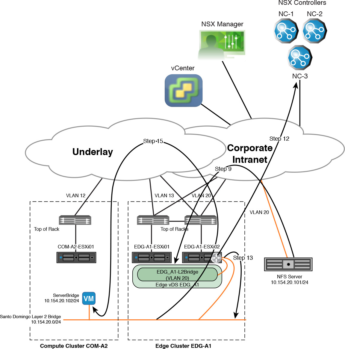
Now on to a packet walk. Figure 10-29 shows two clusters, a VM and a physical NFS server. Each cluster has its own vDS, and the NFS server is in the same subnet (10.154.20.0/24) as the virtual machine (ServerBridge). We do a packet walk of the first ping ServerBridge sends to the physical NFS server. EDG-A1-ESXi02 is the Bridge Instance.
Step 1. Virtual machine ServerBridge wants to ping the NFS server but does not have an ARP entry for the NFS sever in its ARP table.
Step 2. ServerBridge sends an ARP request.
Step 3. The ARP request is received by logical switch Santo Domingo Layer 2 Bridge in ESXi host EDG-A1-ESXi02.
The ARP request was replicated.
Step 4. Logical switch Santo Domingo Layer 2 Bridge in ESXi host EDG-A1-ESXi02, which is the Bridge Instance, broadcasts the frame locally, and a copy is received by the sinkport connected to the LIF of DLR Layer 2 Bridge.
Step 5. Layer 2 Bridge learns the MAC address of ServerBridge and tells the NSX Controller.
Step 6. Layer 2 Bridge forwards the ARP request out of the sinkport connected to the bridged VLAN LIF.
Step 7. The frame is received by vDS EDG_A1’s EDG_A1-L2Bridge dvPortgroup in VLAN 20 in EDG-A1-ESXi02.
vDS EDG_A1 does not learn the MAC address of ServerBridge.
Step 8. vDS EDG_A1 sends the frame out to the physical network, over VLAN 20, where every physical switch in the VLAN learns the MAC address of ServerBridge, as shown in Figure 10-30.
Bridged traffic is pinned to a single dvUplink in vDS EDG_A1.
The ARP request is a broadcast that will be processed by all switches in VLAN 20, including the local copy vDS EDG_A1 running in ESXi host EDG-A1-ESXi02.
Step 9. The physical NFS server receives the ARP request and sends back a unicast ARP reply to ServerBridge.
Step 10. The ARP reply is received by the dvUplink of vDS EDG_A1 in EDG-A1-ESXi02 to which the bridge traffic is pinned.
Step 11. vDS EDG_vDS forwards the frame to all of its interfaces in VLAN 20, including the sinkport connected to the bridged VLAN LIF of DLR Layer 2 Bridge.
Step 12. Layer 2 Bridge learns the MAC address of the physical NFS server and tells the NSX Controller.
Step 13. Layer 2 Bridge sends the ARP reply out of the sinkport connected to the bridged VXLAN LIF.
Step 14. Logical switch Santo Domingo Layer 2 Bridge in ESXi host EDG-A1-ESXi02 gets the ARP reply and learns the MAC address of the NFS server.
The logical switch will not tell the NSX Controller about it. This is where the close working relationship between the logical switch and the DLR comes into play.
Step 15. The ARP reply is forwarded to ServerBridge.
Step 16. ServerBridge adds the ARP entry in its ARP table and sends a ping to the physical NFS server, as shown in Figure 10-31.
If the physical NFS server sends an ARP request for ServerBridge before it can respond to the ping, the steps are similar to steps 1 through 15.
Packet walks could hardly get any simpler than this. A lot of the details were not included here, like the ARP replication, because we have covered them quite a bit. By now you should be familiar with what is happening at the logical switch.
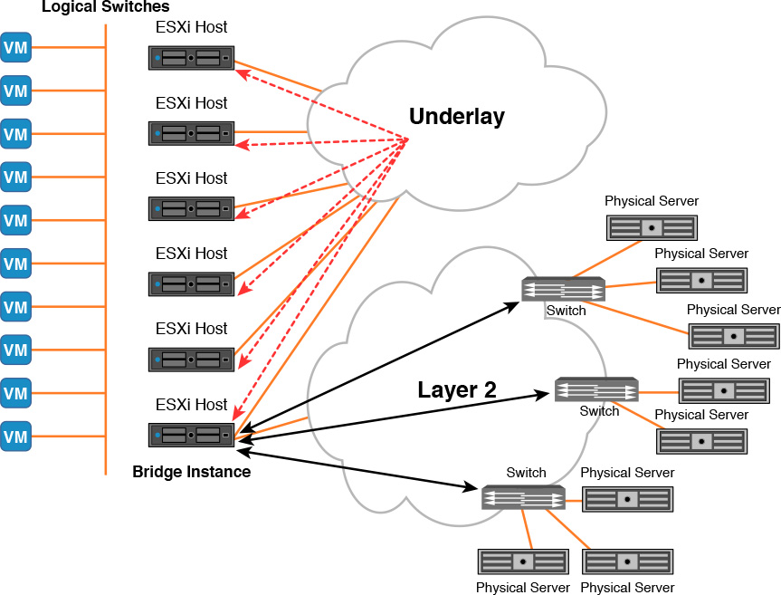
The Layer 2 Bridge is a great way to extend the Layer 2 of your logical switches to VLANs so as to allow virtual and physical workloads that can only communicate via Layer 2 to do so. However, a Layer 2 Bridge has some scalability challenges that may be hard to overcome in some use cases. In Figure 10-32, you can see a sample deployment where multiple physical workloads need to share the same Layer 2 domains with a number of virtual workloads in logical switches. All traffic to/from the physical workloads would go over the same VMNIC in the Bridge Instance. It is easy to see how this may be a bottleneck.
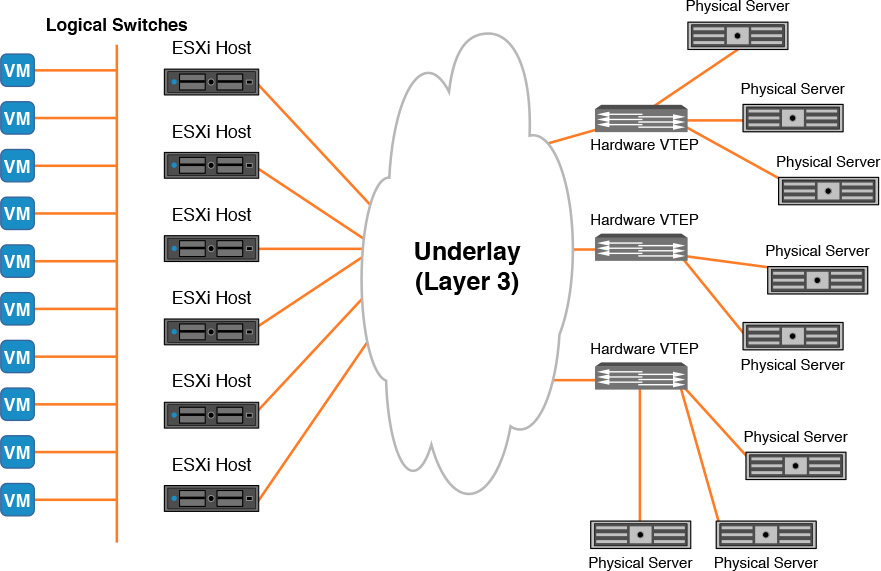
If instead of a Bridge Instance we could have a physical switch do the mapping of VXLAN to VLAN, we could have a deployment with increased available bandwidth and no single link acting as a bottleneck. A switch that can bridge VXLAN to VLAN traffic is called a hardware VTEP.
NSX supports deploying multiple hardware VTEPs to map a VXLAN to a VLAN. This is useful for cases where you have multiple physical workloads connecting to different switches; however, this comes with a big warning to avoid physical Layer 2 loops. Figure 10-33 shows multiple hardware VTEPs being used to extend VXLAN 7321 to VLANs.
Before NSX 6.2, the only option to add a hardware VTEP to the NSX environment was to have logical switches with Multicast Replication Mode. As of NSX 6.2, the hardware VTEPs can also be added to the NSX domain with both Unicast and Hybrid Replication Mode.
To add and verify a switch as a hardware VTEP to NSX, follow these steps. You must be an enterprise administrator or NSX administrator to add a hardware VTEP, the logical switch must already be created in NSX, and the VLAN must exist in the switch.
Note
The steps will reference a Brocade VDX 6740 as the hardware VTEP.
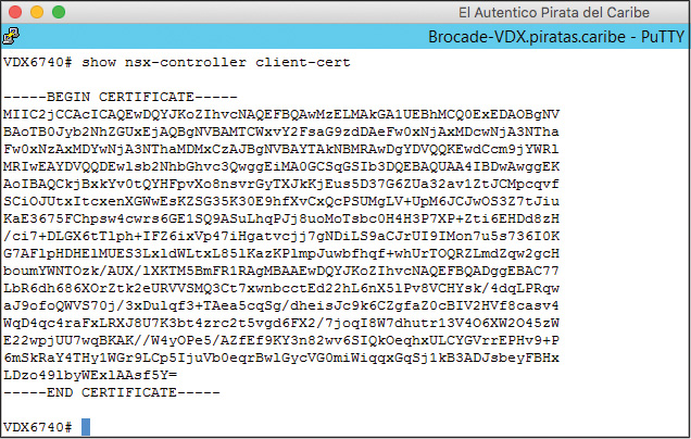
Step 1. In the switch, connect to and activate the NSX Controller API master.
Step 2. Copy the NSX Controller client certificate, as shown in Figure 10-34.
Step 3. In the Network and Security’s Service Definition view, select the Hardware Devices tab.
Step 4. Click the green plus sign to add the hardware VTEP.
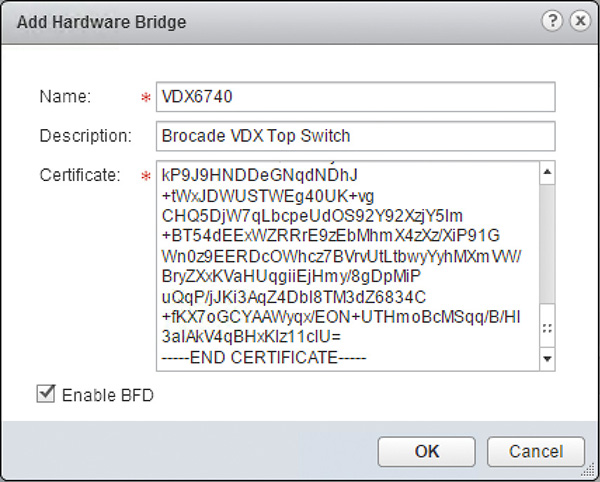
Step 5. In the Add Hardware Bridge pop-up window, assign the Hardware VTEP a name and paste the NSX Controller client certificate as shown in Figure 10-35. Then click OK.
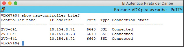
Step 6. Go back to the switch, type the command show nsx-controller brief to confirm the switch has a connection with all three NSX Controllers, as shown in Figure 10-36.
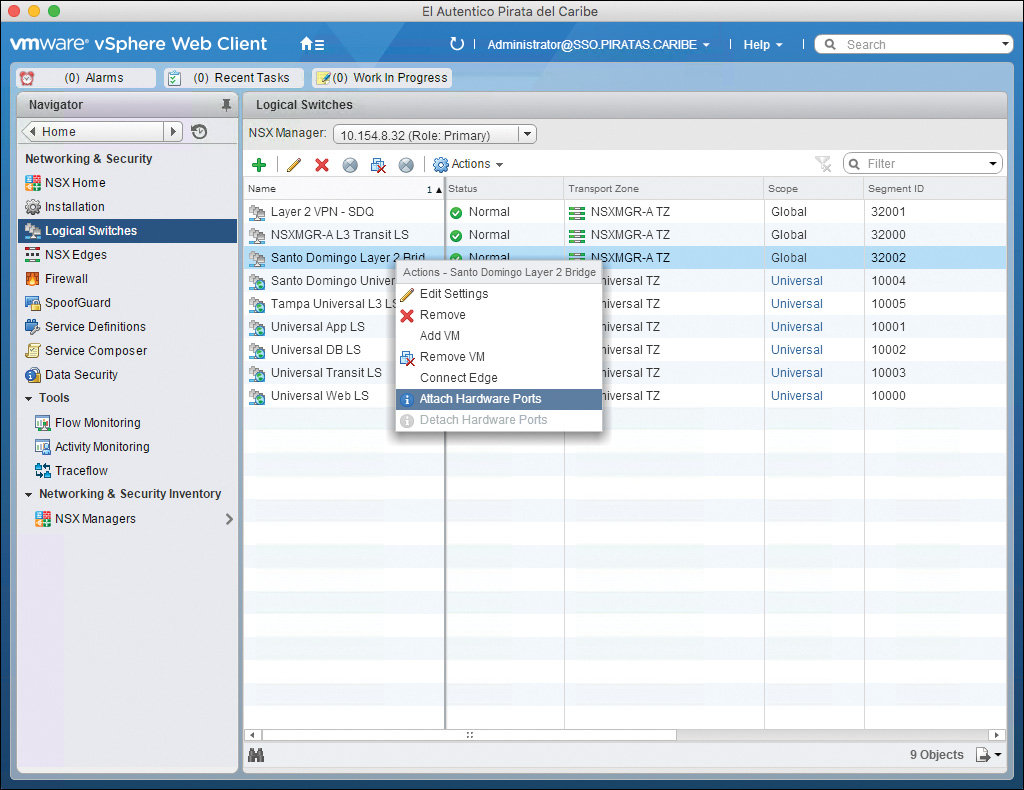
Step 7. From the Networking and Security’s Logical Switches view, right-click the logical switch you want bridged to VLANs and select Attach Hardware Ports, as shown in Figure 10-37.
Step 8. In the Attach Hardware Ports pop-up window, select the following values:
a. Hardware Devices: Select the Hardware VTEP from step 5.
b. Hardware Switch Ports: Click the green plus sign to add VXLAN to VLAN mapping.
i. Switch: Select the switch.
ii. Port: Select a port in the switch to assign the VXLAN to.
iii. VLAN: Enter the VLAN that will be bridged with the VXLAN and click OK.
Repeat step 8 to add more switches to this logical switch.
Step 9. Back in the switch, enter the command show vlan # to see the tunnels from the ESXi VTEPs.
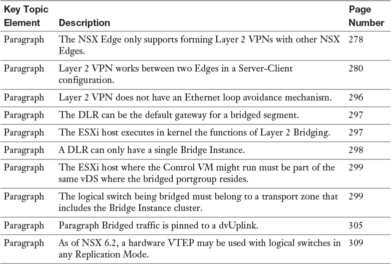
Review the most important topics from inside the chapter, noted with the Key Topic icon in the outer margin of the page. Table 10-5 lists these key topics and the page numbers where each is found.
Download and print a copy of Appendix C, “Memory Tables” (found on the book’s website), or at least the section for this chapter, and complete the tables and lists from memory. Appendix D, “Memory Tables Answer Key,” also on the website, includes the completed tables and lists so you can check your work.
Define the following key terms from this chapter, and check your answers in the Glossary: