10
Connecting Electronics
You can go a long way with the micro:bit just using its built-in sensors and display, but at some point you will probably want to attach some external electronics—maybe to produce sound, power the micro:bit from a battery, connect other types of sensors, or turn something on and off.
Battery Power
Powering your micro:bit is great while you are getting your program working, but sometimes you will need to unplug it from your computer and take your project wireless, for which you will need to power your micro:bit with batteries.
USB Power Pack
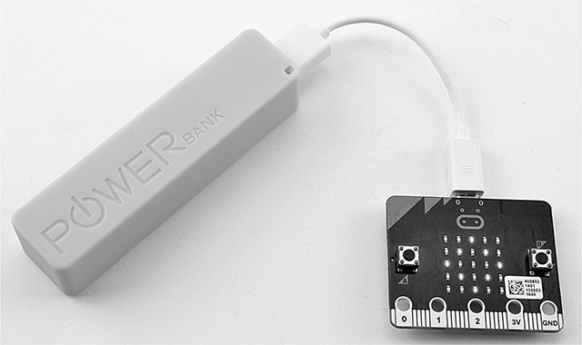
One quick, easy (and rechargeable) way to power your micro:bit with batteries is to use a USB power pack such as the one shown in Figure 10-1.
Figure 10-1 Powering a micro:bit from a USB power pack.
A WORD OF WARNING: The Microbit Foundation specifically advises against using USB battery packs (see www.microbit.co.uk/safety-advice). The foundation says that this is because it is possible to find USB power packs that supply more than the 5 volts (V) expected of them. The USB interface chip that regulates the USB input voltage from the nominal 5 V to 3.3 V (which all the other chips on the micro:bit require) is specified as allowing up to 6 V as its input voltage. In my experience, you would be extremely unlucky to exceed 6 V with a USB power pack because they have their own regulator chips to set their output voltage to a stable 5 V.
It is more risky to use USB phone chargers, especially really cheap ones. These have been known to produce a higher voltage than 5 V to allow for a voltage drop in the wires to the phone to be charged. A micro:bit consumes much less current than a phone being charged and so does not suffer the same voltage drop in the wires. Thus it could receive over 6 V, possibly destroying the micro:bit.
Assuming that you are happy to take the risk of using a USB power pack, the micro:bit uses very little electricity (more on this later), so the smallest USB power pack you can find will be just fine. In fact, the larger, more expensive power packs tend to have an automatic shutoff feature, which means that they turn off if not enough current is being drawn from them, and sometimes this means that they don’t detect the micro:bit and turn themselves off. The power pack in Figure 10-1 was bought for less than $5 and is charged from your computer or any USB power source (incidentally, I measured its output voltage as a very stable and perfectly acceptable 5.15 V).
Powering a micro:bit from a USB power pack actually provides a more stable voltage source to the micro:bit than using 3 V batteries, as described in the next subsection. This is so because the USB connection provides 5 V that is then regulated using a chip on the micro:bit to a precise 3.3 V supply, whereas when using a 3 V battery pack, the actual voltage will vary between 2.6 and 3.2 V depending on how fresh the batteries are.
3 V Battery Pack
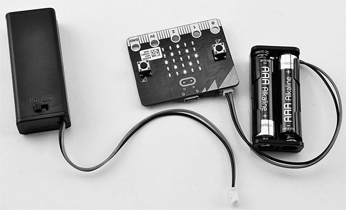
The micro:bit has a special connector to which a battery pack can be attached. Figure 10-2 shows a 2 × AAA battery pack powering a micro:bit. Next to it is a second type of battery pack that very usefully incorporates a switch so that you can turn the micro:bit on and off without having to plug and unplug the connector. The battery socket has a slot on one side, so it can only be connected the correct way.
Figure 10-2 3 V battery packs.
Note that when you are powering a micro:bit from its 3 V connector, the power LED does not light, so it can be difficult to detect whether your batteries are okay unless you have something being shown on the display.
Battery Life
A micro:bit consumes about 19 milliamperes (mA) of current with none of the display LEDs lit. It then consumes a further 1 mA for each LED. So if you assume that half the LEDs will be lit on average, then the micro:bit will consume a total of around 30 mA. If you use the micro:bit’s radio (see Chapter 11), you may use another 10 mA or so. Table 10-1 shows how long various power sources will power a micro:bit, assuming an average current consumption of 30 mA.
Table 10-1 Battery Life When Powering a micro:bit

micro:bit Operating Voltage
The means of powering your micro:bit—USB or AAA batteries—has quite a large effect
on the operating voltage of your micro:bit. This operating voltage is important because it will be the actual
voltage on the edge connector pin marked “3V” and also determines the logical HIGH output voltage when a general-purpose input/output (GPIO) pin is used as an output.
Table 10-2 shows the actual voltage appearing on the 3 V pin for various sources and conditions.
Table 10-2 The micro:bit Operating Voltage for Different Power Sources

All the voltages measured on the 3 V pin are measured at about 0.14 V less than you might expect. The USB supply is regulated down to a precise 3.3 V by the USB interface chip, so you would expect the operating voltage to be 3.3 V, but instead it’s 3.16 V. This is so because it takes 0.14 V for the circuit to allow automatic switching between battery and USB power.
GPIO Pins 0, 1, and 2
GPIO is short for “general-purpose input/output”—“general purpose” because such pins can operate in different ways:
 Digital output—turns something on or off
 Analog output—controls the amount of power going to something
 Digital input—detects an on/off signal such as a switch being pressed
 Analog input—measures a voltage
GPIO “pins” on the edge connector are clearly not very pin-like. They are gold-plated holes to which you can attach an alligator clip. The term pin comes from the fact that they are connected to pins on the micro:bit’s microcontroller chip.
In this section, we will concentrate on the three easily accessible pins 0, 1, and 2. Later in this chapter, you will learn about the other pins available on the micro:bit’s edge connector.
Alligator Clip Leads
Figure 10-3 show a lead terminated in alligator clips (also known as crocodile clips). These leads are really useful for attaching things to your micro:bit. Having a range of colors for your lead is also useful, and it’s a good idea to make leads to 3 V red (for positive); leads to ground (GND) black, blue, or green; and other leads various other colors.
Figure 10-3 A lead terminated in alligator clips.
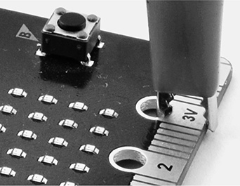
Alligator clips are so named because they resemble the jaws of an alligator. When you squeeze the back of the clip, the jaws at the front open and can be clipped onto the large hole connectors on the micro:bit edge connector to connect the micro:bit up to other devices. When you attach a clip to the edge connector of your micro:bit, it’s best to do it vertically, as shown in Figure 10-4. Otherwise, the clip can accidentally connect the big pad on the edge connector to the smaller pads on either side.
Figure 10-4 Connecting an alligator clip to a micro:bit.
Digital Outputs
If you use a GPIO pin as a digital output, your program can set the pin to be HIGH (3 V, but see the section “micro:bit Operating Voltage”) or LOW (0 V). If you then connect this output to one leg of a LED and the other end of the
LED to 0 V (via a resistor to limit the current), then when the pin is HIGH (3 V), there will be a difference in voltage across the LED and resistor that will
cause a current to flow, making the LED light up. (For information on buying LEDs,
resistors, and indeed any other components and hardware for your micro:bit, see Appendix B.)
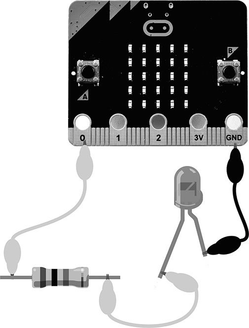
Figure 10-5 shows this arrangement built using alligator clips. The LED has a positive and a
negative end; the positive lead is slightly longer than the negative lead. The LED
will be controlled from pin0.
Figure 10-5 Connecting a LED to a micro:bit.
The reason that you should not just connect the LED directly between the GPIO pin and GND (0 V) is that the LED will draw more than the allowed (in the micro:bit’s specification) 5 mA from the pin without a resistor to restrict the flow of current to 5 mA. The value of the resistor must be 330 ohms (Ω) or more. You probably could “get away” with attaching a LED directly, but doing so may damage your micro:bit. It will not destroy it immediately, but the heating on the surface of the chip around the area responsible for the GPIO pins can shorten the life of the chip. In any case, using a resistor with a LED is a good habit to get into should you move on to using less forgiving boards.
The micro:bit’s GPIO pins are actually quite robust, so even connecting a high digital output directly to GND only causes a current of 15 mA to flow. This is still three times what the micro:bit specifications recommend, but as long as you recognize your mistake and remove the short circuit, your micro:bit should survive.
When it comes to modern high-brightness LEDs, they are so efficient that even if you use a 1 kilo ohm (kΩ) resistor limiting the current to 1.7 mA, they will still be plenty bright enough and be well below the 5 mA maximum.
If you have a LED, a resistor, and some alligator clips, connect them together as
shown in Figure 10-5. Flash the program ch10_blink.py onto your micro:bit, and the LED should blink once per second. If it doesn’t, check
that the LED is the right way around. Note that if it’s the wrong way around, no harm
will befall the LED or the micro:bit; the LED just won’t work.
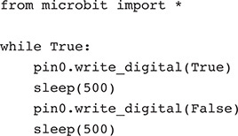
To use the micro:bit’s pins, you use variables defined in the microbit module for each pin. These are named pin0, pin1, and pin2 for the main alligator clip–friendly pins. Each is an instance of the class MicroBitTouchPin.
The write_digital method sets the output of the pin to 0 V if its parameter is False and to 3 V if its parameter is True. The two calls to sleep slow down the blinking of the LED to once per second.
If you have used an Arduino or Raspberry Pi, you may be expecting to have to set the
mode of the pin to input or output before using it. This is not necessary with the micro:bit; if you try to use write_digital on a pin, the micro:bit assumes that you are using the pin as a digital output, and
if you use read_digital with a particular pin, it sets that pin to be an input.
Because of the low current-handling capability of the GPIO pins (it’s not recommended
to draw more than 15 mA in total from these pins), digital outputs are usually used
as signals to other electronic devices that then handle the larger current. If you
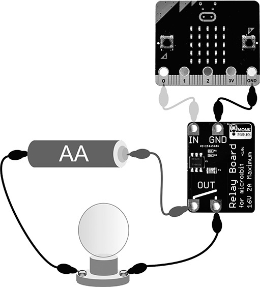
have a larger current to switch, then you can use a relay board such as the MonkMakes
Relay for micro:bit. Figure 10-6 shows one of these devices in action. A HIGH level at the IN connection makes an electronic switch integrated circuit (IC, called a solid-state relay) conduct so that the two connections marked OUT are connected together, completing a circuit to turn on a light bulb. The input signal
only needs to supply about 3 mA, but the output can switch 2 A at up to 16 V. The
input and output are not electrically connected.
Figure 10-6 Using a MonkMakes relay module.
Analog Outputs
In addition to simply turning a LED on and off, you can also control the brightness
of a LED by using the write_analog method instead of write_digital. Rather than simply accepting True or False for on and off, the write_analog method takes a value between 0 (off) and 1023 (full power).
Using the same arrangement of a LED attached to pin0 as in Figure 10-5, run the program ch10_brightness.py. Pressing button B will increase the brightness, and pressing button A will decrease
the brightness.
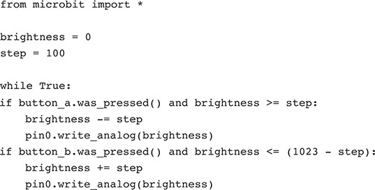
Two global variables are used. The variable brightness contains the current brightness (remember that the maximum is 1023), and the step variable is used to determine how much to increase or decrease the brightness each
time you press a button. The code just detects button presses and increases or decreases
the brightness while being careful not to go out of the allowed range of 0 to 1023.
The way that write_analog changes the brightness of the LED is not (as you might quite reasonably think) to
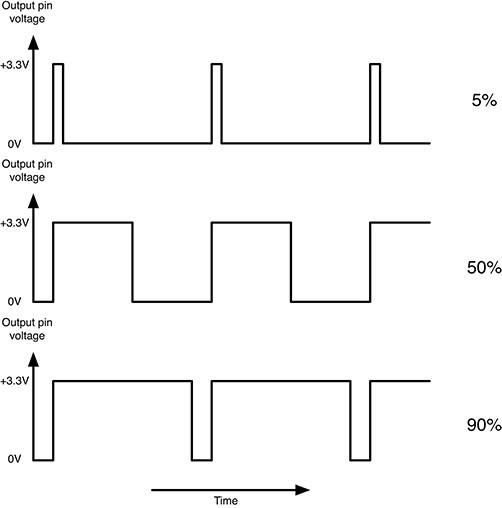
vary the voltage between 0 and 3 V, but rather it uses a technique called pulse width modulation (PWM). PWM (Figure 10-7) controls the power going to the LED by producing a continuous stream of pulses.
On the micro:bit, this is at a rate of 50.3 pulses per second, but you can adjust
it using set_analog_period or set_analog_period_microseconds.
Figure 10-7 Pulse width modulation.
If the pulse is only HIGH for a very short time (say 5 percent of the time), then only a small amount of power
is delivered to the LED, so it will be dim. The more time the pulse is HIGH, the more power is delivered to the LED, and the brighter it will be.
PWM also works for controlling the speed of motors, although motors use a lot more current than the 5 mA limit of a micro:bit’s GPIO pin, so do not try to connect a motor directly. You could use a MonkMakes relay board to control a motor using PWM. This is possible because the MonkMakes Relay uses a solid-state relay with no moving parts. You should not use an old-fashioned electromechanical relay for PWM.
Digital Inputs
A push switch is a good example of a digital input to the micro:bit. Such a switch is digital in the sense that it can only be either on or off. It cannot be anywhere in between. The two switches built into the micro:bit are connected to GPIO pins (5 and 11) used as digital inputs.
You can test digital inputs by using a crocodile clip to connect pin0 to either 3 V or GND. Flash the program ch10_digital_input.py onto your micro:bit, and then try connecting the alligator lead from pin0 to 3 V (Figure 10-8A) and then from pin0 to GND (Figure 10-8B).
Figure 10-8 Testing digital inputs on the micro:bit.
Be careful when connecting things to GPIO pins that are used as digital inputs because the voltage should not exceed 3.6 V, so connecting, say, 5 V to a digital input could destroy your micro:bit.
Analog Inputs
Whereas a digital input can only be on or off, analog inputs allow you to measure the voltage at a pin. The voltage must be between 0 V (GND) and the supply voltage (3V). Trying to measure higher voltages than this could destroy your micro:bit.
Flash the program ch10_voltmeter.py onto your micro:bit, and then try repeating the experiment of the preceding section,
connecting pin0 first to GND and then to 3 V. You will see the voltage reading on the display change.
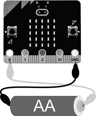
An AA or AAA battery has a voltage of around 1.5 V, so find yourself a battery, and use this project to measure the voltage of the battery. If like me you have a box full of batteries of indeterminate age and charge level, then you can use this as a battery tester. Connect the battery as shown in Figure 10-9.
Figure 10-9 Using a micro:bit as a battery tester.
WARNING: Be careful. If you connect the battery the wrong way around, you could destroy your micro:bit. The negative battery terminal must be connected to GND on the micro:bit.
Here’s the code for this project:

The function read_analog returns a number between 0 and 1023. A return number of 0 means 0 V, and if you are powering your micro:bit via USB, then a reading of 1023 would indicate 3.16 V (actually, the operating voltage). So if you get a reading
of 511 (about half of 1023), then that would mean about 1.58 V.
To convert a reading value of between 0 and 1023 to a voltage of between 0 and 3 V, you need to first multiply the reading by 3.16
and then divide it by 1023. Finally, the voltage reading is formatted to one decimal
place using the formatting string.
I mentioned earlier that if you are powering your micro:bit from its USB connector,
then a reading of 1023 would indicate 3.16 V, the implication being that if you powered it from batteries,
this would be something else. This is so because when you power your micro:bit powered
from a battery pack, its supply voltage can be anything from 2.6 to 3.2 V depending
on how fresh the batteries are. When your micro:bit is powered from batteries, a reading
of 1023 indicates the operating voltage of the micro:bit.
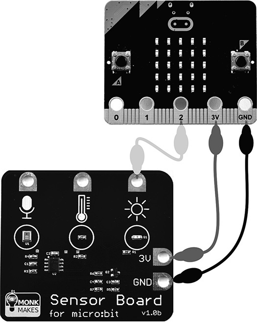
Analog inputs are often used as a way of connecting sensors to a micro:bit. The MonkMakes sensor board (Figure 10-10) has sound, temperature, and light sensors, each of which produces an output voltage between zero and the micro:bit’s operating voltage depending on the sound, temperature, or light level.
Figure 10-10 The MonkMakes sensor board for micro:bit light sensing.
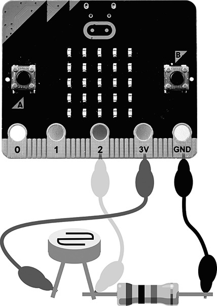
If you have a photoresistor and fixed-value resistor, you can also make a light-sensing
circuit if you connect them up as shown in Figure 10-11. Both this arrangement and the preceding one will work with the same program (ch10_voltmeter.py), with the voltage reading being an indication of the light level.
Figure 10-11 A light sensor using a photoresistor.
Power Out
When you power your micro:bit via USB, the regulator built into the USB interface chip on the micro:bit produces a steady 3.3 V for the micro:bit’s various processors and sensors. The regulator is capable of supplying 120 mA before it gets too hot and turns itself off. This means that after the micro:bit has taken about 30 mA from the regulator, up to 90 mA will be available on the 3 V edge connector for your projects.
Sound Output
There are various ways of giving your micro:bit the ability to make a noise. In this
section, we’ll start by looking at the various connection options, and then we’ll
look at how you can write code to play tunes and even make your micro:bit talk. The
micro:bit can produce an audio signal on one of its pins (by default pin0) by making the pin oscillate from LOW to HIGH hundreds or thousands of times a second. The faster the oscillation, the higher is
the pitch of the sound produced.
Alligator Clip to Audio Socket
The GPIO output cannot supply enough current to be safely connected directly to a loudspeaker, but it can drive a small in-ear headphone. However, first you would need to connect one.
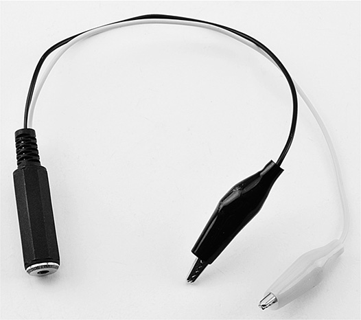
The easiest way to do this is to use an alligator clip to audio socket adapter such as the one shown in Figure 10-12. These adapters can be found on eBay or Amazon for a few dollars. Having a standard audio socket connected to your micro:bit also means that you can attach a powered loudspeaker to it such as the one shown in Figure 10-13.
Figure 10-12 An alligator clip to audio socket adapter.
Figure 10-13 Connecting a powered speaker to a micro:bit.
Amplifier Modules
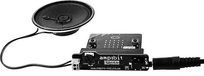
Another way to attach a speaker to your micro:bit is to use an amplifier module such as the MonkMakes Speaker for micro:bit (Figure 10-14) or Proto-PIC’s amp:bit (Figure 10-15).
Figure 10-14 The MonkMakes Speaker for micro:bit.
Figure 10-15 The Proto-PIC amp:bit.
The Speaker for micro:bit connects using alligator clips, whereas the amp:bit uses the micro:bit’s edge connector, and the micro:bit is plugged directly into the amp:bit. The amp:bit also provides a volume control.
Updating the Alarm Project
You may remember that I promised that the timer project would have an audible alarm added to it. Now that you have several ways of adding sound to your micro:bit, you can add this to the project.
Connect your chosen arrangement of speaker, and then upload the program ch10_timer_final.py. Try out the project, and when the timer completes, the alarm will sound with a pleasing
tone.
To play the sound, the music library must be imported at the top of the program. The other changes are to be found
in the handle_run_state and handle_alarm_state functions.
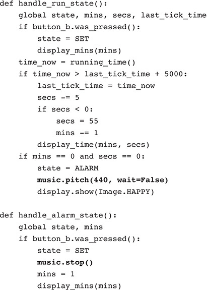
The music method pitch has a parameter of the pitch (frequency in hertz) of the tone to be generated. By
default, this would continue indefinitely, and we would not be able to cancel the
tone by pressing a button, so the optional wait parameter is set to False so that our code can detect a press of button B. To stop the music playing when the
mode is changed back to SET, the stop method is called. If you decide to use a pin other than pin0 to generate the sound, the play and stop methods must be supplied with an optional pin parameter.
Music
In addition to just playing a tone, the music module has a beautifully designed musical notation that lets you play tunes. A tune
is contained in a List of strings, with each string being one note. Only one note
can be played at a time. To get the hang of this notation, with your sound hardware
attached, open the REPL and try a few commands:

The first part of the string is the note letter. This can optionally be followed by an octave number.
The music module also allows you to specify note duration, sharps and flats, and even a time
signature. Rather than rewrite the already excellent documentation on this module,
please refer directly to https://microbit-micropython.readthe docs.io/en/latest/music.html.
Speech
Another useful module that you can import into your programs is the speech module. Note that although the official documentation for the module (https://microbit-micropython.readthedocs.io/en/latest/tutorials/speech.html) tells you to wire a speaker between pin0 and pin1, if you are using a powered speaker such as the MonkMakes Speaker for micro:bit or
a headphone adapter lead, you can connect up normally using pin0, as described earlier.
The speech generation sometimes requires some careful listening to hear the message properly, but it is a fun thing to add to a project. Try out the following commands in the REPL:

If you want to vary the pitch or timbre of the voice and even make your micro:bit sing, then take a look at the official documentation for this module.
Neopixels
In addition to simple LEDs such as the red LED used earlier in this chapter and the 25 LEDs that make up a micro:bit’s display, there are more advanced LEDs (often called neopixels) with built-in chips that allow you to control the color of the LED. These LEDs are designed to be daisy-chained so that you can have a long chain of neopixels, each one connected to the preceding one. A single data pin is used to specify the color each LED is to display by sending a long stream of information.
Fortunately, there is a MicroPython module for using neopixels, and so you don’t need to get involved in constructing the data. You can just specify a color for each neopixel in the chain. Figure 10-16 shows a very neat neopixel-based display that plugs into the micro:bit’s edge connector.
Figure 10-16 The Proto-Pic micro:pixel edge.
You can buy neopixel displays on a reel of tape that can be cut to the number of neopixels you want, as well as various arrangements of the neopixels, including grids of pixels, even when arranged in a grid on a board. The limitations of the micro:bit’s power supply mean that you can only power about eight neopixels from a micro:bit without having to use a separate power supply. You may also have problems powering this project with a 3 V battery pack because unless the batteries are really fresh, there will probably not be enough volts for the neopixels’ liking.
When powering neopixels directly from the micro:bit, one data pin is used; the GNDs of the neopixel display and the micro:bit need to be connected, as does the 3 V supply to the neopixels. Neopixels will work at 3 V, but for full brightness, they should be powered at 5 V via a separate power supply.
Flash the program ch10_neopixels.py onto your micro:bit. The display will produce a light-chasing effect.
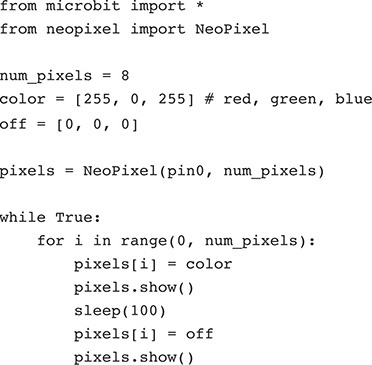
All the code for using the neopixels is contained in the class NeoPixel imported from the built-in module neopixel. When you create an instance of this class, you specify the number of pixels in your
display, which for convenience is kept in the global variable num_pixels, so you will need to change this if your neopixel display does not have eight LEDs.
A variable color is used to hold the color to be displayed on the LED. The color is represented as
a List of three values. Each value must be between 0 and 255 and represents the amount of red, green, and blue that will make up the color of
the LED. So the color [255, 0, 255] is maximum red, no green, and maximum blue, producing a magenta color. The variable
off contains the three zeros needed to turn the LED off entirely.
The loop steps over each pixel position in turn, lights the LED in the chosen color,
delays, and then turns the LED off again. Note that the change to any pixel pattern
is not actually shown until you call pixels.show.
The Edge Connector
In addition to the five alligator lead–friendly connectors on the micro:bit, you will have noticed the much smaller connectors in between the large connectors. These are only accessible by plugging the micro:bit into a socket, such as the one shown on the Proto-Pic micro:pixel edge shown in Figure 10-16.
There are many other types of expansion boards for the micro:bit, including motor controllers, various types of displays, and audio interfaces. You will find suppliers for these and some of their products listed in Appendix A.
In addition to connecting a ready-made expansion board to your micro:bit, if you acquire an adapter, you can gain access to all the pins of the GPIO connector for more advanced projects than are possible with just the pins 0 to 2. You can find a lot more detail about the edge connector at http://tech.microbit.org/hardware/edgeconnector_ds/.
Pinout
Although the edge connector has 25 connections, this does not mean that you get 25 GPIO pins to use. Quite a few of the connections are for GND and 3 V, and many of the connections are also connected to pins that are used to drive the display or for the buttons. Pins that are totally free to use for your own purposes are 0, 1, 2, 13, 14, 15, 16, 19, and 20. Figure 10-17 shows the pinout for the connector.
Figure 10-17 The micro:bit edge connector pinout.
Pins 0, 1, 2, 3, 4, and 10 can all be used as analog inputs. Pins 13, 14, and 15 can be used as GPIO pins (but not analog inputs) and also can be used for an interface called the serial programming interface (SPI), which some chips and modules use. Similarly, pins 19 and 20 can be used for a more common type of interface called I2C (pronounced “I squared C”), which also can be used by various types of modules and integrated circuits.
Breakout Boards and Kits
A solderless breadboard is a plastic block with holes in the top and metal clips behind the hole to make it easy to connect electronic components such as LEDs, resistors, and photoresistors. To be able to connect the pins from the micro:bit’s edge connector to the breadboard, you need an adapter such as the Proto-PIC bread:bit shown in Figure 10-18.
Figure 10-18 Connecting a micro:bit to a solderless breadboard.
Taking this a stage further, the Proto-PIC exhi:bit (Figure 10-19) provides a whole platform for connecting to the micro:bit in many ways, including adding alligator clip–friendly connectors for all the pins of the edge connector.
Figure 10-19 The Proto-PIC exhi:bit.
Appendix A provides links for other breadboard adapters as well as kits based on an adapter, breadboard, and some components.
Disabling Hardware
As you saw in Figure 10-17, many of the GPIO pins on the edge connector are used for the display and buttons. If you need to use these pins and don’t need the display, then you can turn off the display and free up the pins it uses with the command:

This will free up pins 3, 4, 6, 7, 9, and 10.
Summary
In this chapter, you have seen the various ways that you can add some extra electronics to your micro:bit. You will also find lots of project ideas on the Internet.
