9
micro:bit Sensors
One way that the micro:bit scores over rivals such as the Arduino is that it has a number of built-in sensors that you can use without having to attach any external electronics. It has an accelerometer that you can use to detect movement gestures and a magnetic compass as well as the ability to detect touch. In this chapter, you will explore these various sensors.
Buttons Revisited
Before we look at the real sensors, let’s look in a little more detail at the built-in
A and B buttons. So far we have used the was_pressed method to detect button presses, but there are some other methods:

is_pressed() returns True if the button is actually pressed at the time the method is called.

was_pressed() returns True if the button has been pressed at some time between when you last called this method
and the time you are calling it now. Using this method means that you can’t “miss”
button presses because the program was doing something else when the button was being
pressed.

get_presses() returns the total number of presses since the last time you asked.
Gestures
Gestures are the easiest way to use the micro:bit’s accelerometer. The most common use of the accelerometer is to check for the orientation of the micro:bit and sudden events such as the micro:bit being dropped, both of which can be done using gestures.
We first met gestures back in Chapter 5 in ch05_gesture_detector.py, which displays the orientation of the micro:bit as you tip it one way or another.
Other gestures detect the levels of shock (maximum acceleration exceeding 3g [three times gravity], 6g, and 8g) as well as freefall. Freefall is difficult to test without access to space travel
or a desire to drop your micro:bit onto the floor (both risky things to do). Similarly,
the acceleration gestures of 3g, 6g, and 8g are also quite hard to test without giving your micro:bit a good bashing.
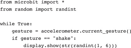
Perhaps the most useful of these other gestures is shake. As the name suggests, this just detects that the micro:bit has been shaken. You
can use it to make a very simple die that displays a random number between 1 and 6
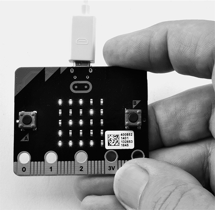
each time you shake the micro:bit (Figure 9-1). You can find this in ch09_dice.py.
Figure 9-1 A simple die.
Raw Accelerometer Data
In addition to using the micro:bit’s gesture detection, you can also gain access to
the raw data from the accelerometer if what you want to do can’t be done using gestures.
To get a feel for the type of data you get back from the accelerometer, run the program
ch09_accl_test.py with the REPL open so that you can see the output.

You should see output like this if your micro:bit is lying more or less flat:
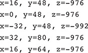
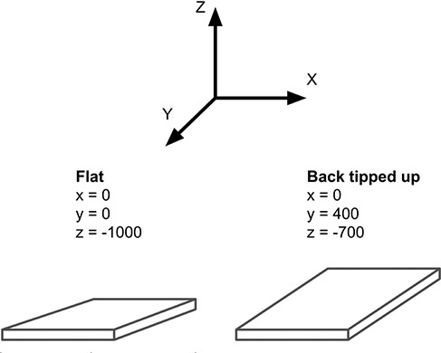
Try moving the micro:bit around to see how the readings change. Figure 9-2 shows how the accelerometer works.
Figure 9-2 How an accelerometer works.
The accelerometer actually measures the forces on a tiny weight contained in the accelerometer
chip. The constant (and biggest) force acting on the accelerometer is the force of gravity. With the micro:bit level, this force is in
the z dimension. This is vertical. The y direction is from front to back of the micro:bit, and the x direction is from left to right. Note that the x and y are the same as for the display. When you tip the micro:bit (and hence its accelerometer
chip) a little, some of the force of gravity starts to act on the other dimensions,
changing the x and y readings.
The program ch09_movement_detector.py monitors the acceleration on just the x axis, and if it changes by more than a certain threshold, a message is displayed.
Increasing the value of THRESHOLD will make the detector less sensitive. See if you can pick up your micro:bit without
triggering the alarm.
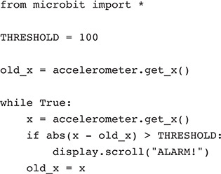
Although I picked the value of acceleration in the x dimension, any of the other dimensions would work equally well.
Note the use of the abs built-in function when checking whether the change in reading has exceeded the threshold.
The abs function returns the absolute value of a number, which is just a fancy way of saying that if it’s negative, it removes
the minus sign.
After reading Chapter 10, you might like to return to this project and add a buzzer or speaker that sounds when the micro:bit is moved.
Magnetometer
In addition to an accelerometer, the micro:bit also has a built-in three-axis magnetometer
(or digital compass) chip. This senses the strength of a magnetic field in each of
the three x, y, and z directions. This can be used as a compass, and at its simplest, you can just use
the method compass.heading, which returns the bearing as an angle between 0 and 360 degrees, where both 0 and
360 degrees are magnetic north. If your phone has a compass app and you’ve tried using
it, then you’ll have an idea of how useful it is as a compass. Generally speaking,
the results are not great with the micro:bit, and like a phone app, you will need
to calibrate the compass using the method compass.calibrate. The example ch09_compass.py shows a ^ on the display when your micro:bit is facing “northish” and a V when it is facing more or less south.
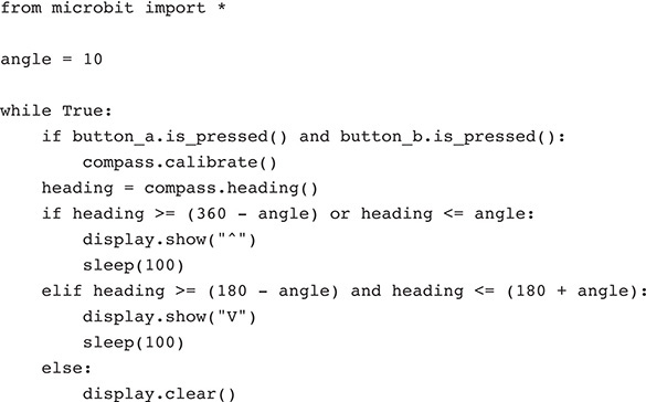
The compass knows whether it has been calibrated, and if it hasn’t—or a new program has been flashed onto the micro:bit—it starts a calibration routine that asks you to tilt the micro:bit so as to produce a circle of dots around the outside of the display. Once this is done, the calibration will be remembered, but you can force a recalibration at any time by pressing both micro:bit buttons at the same time.
In the same way as the accelerometer has a high-level gesture interface and also low-level
routines to read the raw data, the compass also has a low-level interface that allows
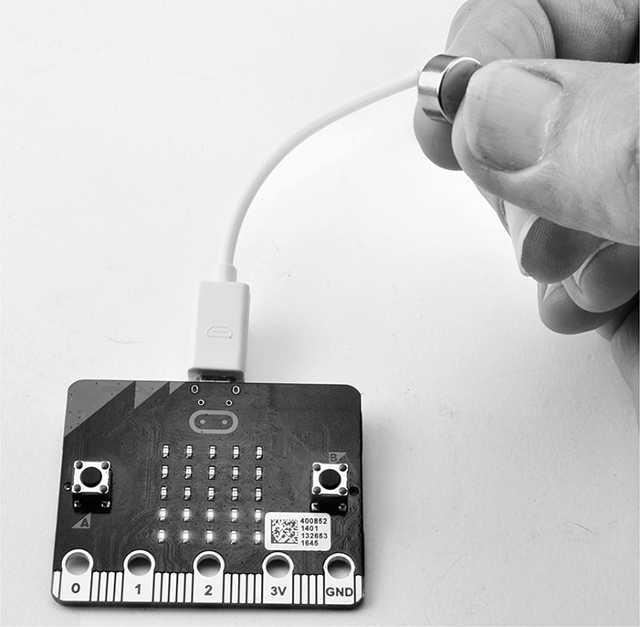
you to read the strength of magnetic field in the x, y, and z directions. You can use this low-level interface to detect a magnet (for best results,
use a “neo” neodymium magnet) and even to get an idea of how near or far the magnet
is from the micro:bit (Figure 9-3).
Figure 9-3 Detecting a magnet.
You will find the program for this in ch09_magnetometer.py. Try moving a magnet near button B (the magnetometer chip is close to button B on
the underside of the board), and you should see the number of bars change as you move
the magnet closer and further away.
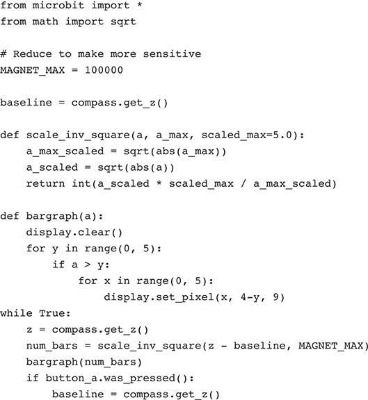
The global variable MAGNET_MAX is all in uppercase letters to highlight it as a constant. This is a value that won’t
change when the program is running, but you might want to change it before running
the program. It is used to scale the reading and control how many rows of LEDs will
be lit. As the comment above it suggests, reduce this value to make the meter more
sensitive.
The global variable baseline is used to hold the background field strength read before a magnet is placed near
the micro:bit. It is initialized to the z-axis reading of the magnetometer.
The strength of magnetic field at a certain distance from the magnet follows what
is called an inverse square law. This means that if you start out 2 inches from the magnetometer and take a reading x and then move to 4 inches away (the distance has doubled) and now take another reading
(y), y will not be one-half of x but one-quarter of x. The function scale_inv_square takes three parameters: a reading from the magnetometer, the maximum expected reading,
and the maximum value of result (scaled_max). The parameter scaled_max defaults to 5 to give five bars on the display. The function takes the square root
of both the measurement and the maximum expected readings (after removing the signs
using abs) and then returns the ratio scaled by scaled_max.
To display a number of rows between one and five for the reading, the function bargraph uses a for loop to count using y from 0 to 4, each time selecting a row. If the value supplied as the parameter a exceeds the current row number, then the whole row of pixels is lit by another for loop. Note that in the call to set_pixel, the y coordinate is 4-y to flip the display so that the bars start from the bottom of the display rather
than the top.
The main loop takes the magnetometer reading on the z axis and then displays the difference between it and baseline. It then checks for a press of button A, and if there is one, it resets the value
of baseline.
Processor Temperature
The micro:bit’s microprocessor has a built-in temperature sensor. You can access this to measure the temperature, but it will give a reading that is somewhat higher than the ambient temperature. You can try out this feature in the REPL as follows:

The temperature is reported in degrees centigrade; to convert to Fahrenheit, multiply by 9/5 and then add 32.
Touch
You will learn more about using the edge connector in Chapter 10 when you start to attach external electronics to your micro:bit. However, you can
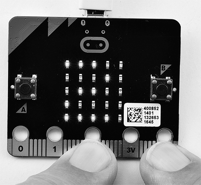
use the points on the connector labeled 0, 1, and 2 as touch buttons (Figure 9-4).
Figure 9-4 Using the edge connector as touch buttons.
Try out program ch09_touch.py to see how this works.
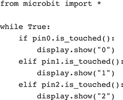
These “pins” are not true touch buttons; you generally need to have a connection to ground (GND) as well as the touch pin, as shown in Figure 9-4. When you touch one of the pins, its number should appear on the display. If this doesn’t work, it may be that your fingers are too dry.
Summary
In this chapter, you have seen some of the sensors that are built into the micro:bit’s circuit board. In Chapter 10, you will take this further and start attaching some other electronic items to the micro:bit.
