Integrated Design
This chapter shows you how to maximize the potential of your site’s water resources by integrating harvested water with sun, shade, and vegetation at your site to help passively cool buildings in summer, heat them in winter, allow for on-site solar power and solar hot water, and enhance plants and gardens. By doing so, you realize the seventh principle of water harvesting: Maximize beneficial relationships and efficiency by “stacking functions.”
Use the strategy of “integrated design” to provide onsite needs (e.g., water, shelter, food, aesthetics) with onsite elements (e.g., stormwater runoff, greywater, cooling shade, warming sun, vegetation, compost) by creating an efficient design that saves resources (e.g., energy, water, transportation, money) while improving the function and sustainability of the site.1 Integrated design helps turn “problems” into solutions. For example, erosive floodwater runoff harvested into basins can provide water to grow shade trees, helping control flooding and erosion. The key is to see, understand, and combine on-site elements—such as stormwater runoff, vegetation, and solar exposure—to maximize their beneficial use.
To help you do just that, this chapter helps you develop an integrated design for your site. Once again we start with observation, this time focusing on the sun’s path across your site, and mapping it along with the other observations you’ve plotted on the site plan you created in chapter 2. Why look at the sun in a water-harvesting book? That is so you can orient buildings, plantings, and more to maximize the degree to which they can produce resources, rather than consume them—by passively and freely heating, cooling, powering, growing, and maintaining themselves in a way that will make all your water resources (and time and money) go further. In that vein, seven basic patterns of integrated design are presented in this chapter to help you create a conceptual layout of water-harvesting earthworks, tanks, gardens, trees, and buildings that work off your observations and build on your site’s existing resources while helping mitigate its challenges. The more patterns you incorporate into your design, the more integrated it becomes. (Appendix 5 provides worksheets prompting you for information to go along with the following seven patterns.) The chapter ends with tips on how to further refine your site’s integrated conceptual design, and gives you an integrated plan example.
Many of you, especially story lovers, may want to skip ahead to chapter 5—the story of how my brother and I created and implemented an integrated plan for our urban lot using design patterns described in this chapter, then worked with others to expand this approach into our neighborhood. Chapter 5 shows you the power and fun of integrating the information and strategies in this book and will feed your hunger for, and understanding of, the important information in this chapter.
NOTE: All times used in this book and chapter are solar time based on the sun’s actual location in the sky, which changes throughout the year. In contrast, clock time is based on an imaginary sun location that results in dividing time into equal 24-hour days throughout the year.
Since solar or true noon—the time of day when the sun is highest in the sky and which divides the daylight hours for that day exactly in half—changes throughout the year, it can be more than an hour different from clock noon. Other solar hours of the day relate directly to solar noon. For example, solar 11 A.M. is one hour before solar noon. The exact date, your location in a time zone, and consideration of Daylight Savings Time will all affect the clock time of your local solar noon and other solar times.
Websites where you can look up solar noon are:
• SunriseSunset.com (United States & Canada)
• TimeAndDate.com (World locations)
• ESRL.noaa.gov/gmd/grad/solcalc
• or the Winter Solstice Shadow Ratio Calculator in the Sun & Shade Harvesting section of HarvestingRainwater.com
THE PATH OF THE SUN
We live on a planet with about a 23.5˚ tilt—(actually closer to 23.44˚) that travels completely around the sun each year. These characteristics result in a gradual shift throughout the year in the direction and time of day that the sun rises and sets, and the angle of the sun above the horizon. The degree of shift depends upon your site’s latitude on earth. (See figure 4.1.)
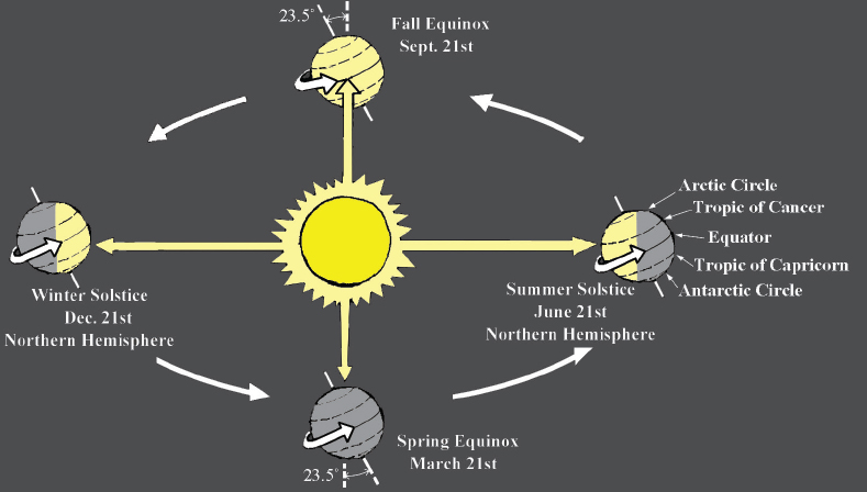
Fig. 4.1. The tilt of the earth’s axis results in gradually changing angles of the sun above the horizon throughout the year. These changing angles of the sun’s rays result in the changing seasons. The more directly overhead the sun is, the hotter it is. The more diffuse the angle of the sun, the cooler it is.
On the winter solstice in the northern hemisphere, the sun is low in the sky at noon and it does not even rise above the Arctic Circle. At the same time in the southern hemisphere, the noonday sun is directly overhead at the Tropic of Capricorn.
On the summer solstice in the northern hemisphere the sun is high in the sky at noon, the sun never sets within the Arctic Circle, and the noonday sun is directly overhead at the Tropic of Cancer.
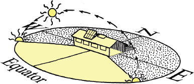
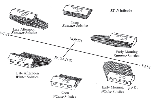
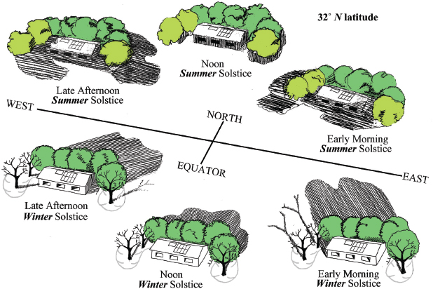
In the northern hemisphere, the sun rises south of due east and sets south of due west in the winter, while it rises and sets north of due east and west, respectively, in the summer. (See figures 4.2A and 4.2B.)
Fig. 4.2A. The winter solstice path of the sun at 32˚ N latitude. House shadow cast at noon. Dotted shading represents section of the sky the sun does NOT traverse.
See appendix 7 for images of the sun’s path at other latitudes.
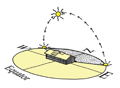
Fig. 4.2B. The summer solstice path of the sun at 32˚ N latitude. House shadow cast at noon. See figures 4.5A and B for shadows cast throughout the day and year.
For videos of these changing sun and shadow paths, and for illustrations of sun paths in the southern hemisphere, see SunAndShadeHarvesting.com.
In the southern hemisphere it is the opposite: The sun rises and sets north of due east and west in their winter (which occurs while the northern hemisphere is having summer), and it rises and sets south of due east and west in their summer. On the spring and fall equinox (March 21 and September 21 in the northern hemisphere; September 21 and March 21 in the southern hemisphere) the sun rises and sets due east and west.
Box 4.1. Don’t Show Your Underaware
Be “sun aware” not “sun underaware.” When I ask people in the United States which side of their house gets directly hit by the rising and setting sun in summer, the majority show me their “under-aware” by saying “due east and west” or “the south side.” In reality the summer sun rises in the northeast and sets in the northwest, directly hitting the north side of their house at those times, important information when planning where to grow cooling shade trees with harvested rainwater.
Observe how the sun affects your site. Go outside in early morning, late afternoon, and midday hours. Watch the sun’s position change throughout the year. How do shadows lengthen and shorten? Where are the warm and cold spots in winter? Where are the hot and cool spots in summer? What areas inside your house get direct sun in the morning and afternoon, in summer and winter? Do you get sun and shade on your garden and outdoor living areas when and where you want it? Create a map of your site’s hot and cold spots through the seasons.
For a simple tool that shows you exactly where in the sky the sun will be at any time of day, any day of the year, for any place on the world, see section two of appendix 7. And check out the Sun Seeker smart phone app.
ORIENT YOURSELF TO THE SUN’S “FLOW” THROUGHOUT THE YEAR
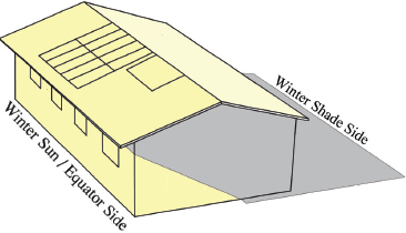
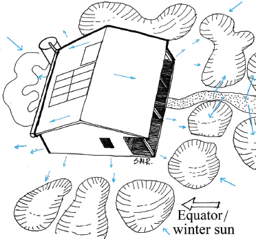
For those living in the northern hemisphere, the south-facing or equator-facing side of buildings, walls, and trees is the “winter-sun side” and the north-facing side is the “winter-shade side.” This is because the winter sun stays in the southern sky all day. Midday the sun’s angle off the horizon remains low (the angle gets lower the further north you are in latitude). (See figure 4.3 and figures A7.1A to A7.7B in appendix 7.)
Fig. 4.3A. Winter sun exposure and shade cast at noon on the winter solstice at 32˚ latitude. Solar hot water heater and solar panels on roof
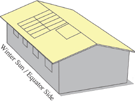
Fig. 4.3B. Summer sun exposure and shade cast at noon on the summer solstice at 32˚ latitude. Solar hot water heater and solar panels on roof
It is the opposite in the southern hemisphere. The north-facing or equator-facing side of the buildings, walls and trees is the “winter-sun side” and the south-facing side is the “winter-shade side.” The winter sun remains in the northern sky.
Identify the equator-facing “winter-sun side,” and the “winter-shade side” of your home now! The rest of this chapter continually refers to this orientation, so get ready and get oriented now!
In summer north of 23.5˚ N latitude (Tropic of Cancer), the sun rises and sets north of due east and west, but at midday the sun is in the southern sky (and higher off the horizon than in winter). So the “summer-shade side” of buildings, walls and trees is the south-facing side in the early morning and late afternoon, but midday it is the north-facing side (with a much shorter shadow than is cast in winter). The converse is true in the southern hemisphere. (See figure 4.2, box 4.2, and appendix 7 for sun angles by latitude and season, for the northern and southern hemispheres.)
Box 4.2. Approximate Sun Angles by Latitude for Northern Hemisphere in Summer (June 21) and Winter (December 21), and for Southern Hemisphere in Winter (June 21) and Summer (December 21)
Find the latitude of your site by looking at a globe, atlas, or topographical map, or web search “What is the latitude of (your town, state, and country)?” Note: The angles in this table have been rounded off for easier reading. See appendix 6, and appendix 7 for more resources on sun angles and passive solar design.
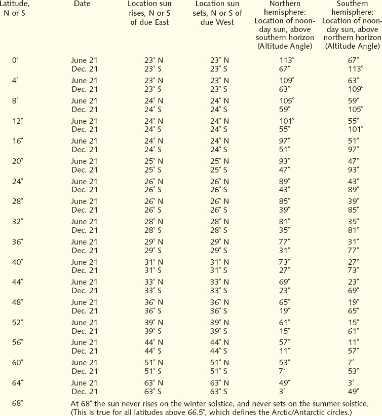
Note 1: Within the tropics (less than 23.5˚ latitude), in the northern hemisphere, on the summer solstice, the sun rises north of east and stays in the northern half of the sky all day long. In the tropics of the southern hemisphere, on the summer solstice, the sun rises south of east and stays in the southern half of the sky all day long. This is shown as a summer noonday sun location of greater than 90˚ in the chart on the previous page. (Note that this does not occur the whole summer, only for a period of time around the solstice, which varies with latitude.)
Note 2: The difference between the location of the noonday sun on the summer and winter solstice is shown as 46˚ for every latitude. This is about twice the Earth’s tilt of 23.44˚, upon which all figures in this chart are based.
Note 3: Noon is solar noon (the point at which the sun is highest in the sky on that given day), not clock noon.
NOAA Solar Calculator: Find sunrise, sunset, solar noon, and solar position for any place on earth at http://www.esrl.noaa.gov/gmd/grad/solcalc/
Residents of the tropics (from 23.5° N and S latitude to the equator) have a different situation. In summer in the northern tropical latitudes, the sun also rises north of due east and west, but unlike the non-tropic latitudes, the sun stays in the northern part of the sky all day. So the “summer-shade side” of objects in the tropics is the south/equator-side all day long. The converse is true in the southern tropical latitudes (see figures A7.1A and A7.2A in appendix 7).
Identify the “summer-shade side(s)” of your home now!
ADD THE LOCATION OR FLOW DIRECTION OF THE SUN AND OTHER OBSERVATIONS TO YOUR SITE PLAN
Map the location of the rising and setting sun on the summer and winter solstice; where you would like more shade or exposure to sun; the direction or location where prevailing winds, noise, or light come from; the foot traffic patterns of people, pets, or wildlife; and any other resources or challenges you may want to design for (fig. 4.4). By recording your site’s existing resources and challenges you can improve the layout and design of water-harvesting earthworks, tanks, gardens, shade trees, paths, and buildings so they harvest more resources and diffuse or divert the challenges.
Fig. 4.4. Map the resources to harvest, and challenges to divert or diffuse on your site, sample map. See appendix 5 for worksheets. Overlay these observations with those of water flow (fig. 2.4) then create an integrated plan that harvests multiple resources while diffusing multiple challenges (fig. 4.27).
SEVEN INTEGRATED DESIGN PATTERNS
Now use the following integrated design patterns to get ideas on how you can efficiently arrange elements of your design to the unique conditions and needs of your site. You will want to have your site map (and worksheets from appendix 5) handy on which to write any additional information. All “Action Steps” discoveries and calculations should be written on your worksheets for further reference. These patterns have a sequence, as you will see.
INTEGRATED DESIGN PATTERN ONE
ORIENTING BUILDINGS AND LANDSCAPES TO THE SUN
Integrate the orientation of buildings, living spaces, and water-harvesting earthworks/planting areas with the sun to maximize passive heating and cooling while reducing water and power needs. A year-long study in Davis, California, monitored temperatures in two identical apartment buildings with different orientations to the sun. No heating or cooling systems were operated during this year. The study found that apartment units in the building with an east-west orientation (long walls facing south and north) and with small roof overhangs were 17˚F (9.4˚C) warmer in winter and 24˚F (13.3˚C) cooler in summer than apartments in a similar building with a north-south orientation (long walls facing east and west).2 (See figure 4.5.) That is a huge difference! Building, buying, or renting a home with correct solar orientation costs nothing extra, yet it can drastically reduce utility costs and increase comfort by maximizing winter sun warmth and minimizing summer heat.
Fig. 4.5A. This orientation is warmer in winter and cooler in summer. Sun exposure on, and shade cast by, an east-west oriented building at 32˚ N latitude. View of building’s winter-sun/equator side.
Note how the winter-sun side is shaded by the roof overhang at the summer solstice, but not the winter solstice. This ideal building orientation and roof slope is perfect for the inexpensive clustered roof top installation of solar PV panels and a solar hot water heater without special mounting racks.
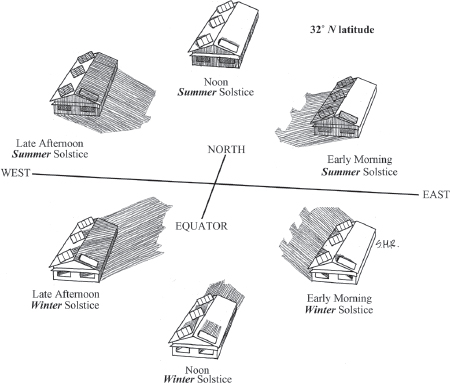
Fig. 4.5B. This orientation is colder in winter and hotter in summer. Sun exposure on, and shade cast by, a north-south oriented building at 32˚ N latitude. View of building’s winter-sun/equator side.
This poor building/roof orientation necessitates a more expensive spread out installation of solar PV panels and water heater so they do not shade one another in winter. In addition, special mounting racks are needed to angle solar panels and water heater correctly toward the sun. More PV panels are also necessary to meet increased power needs of the house’s mechanical heating/cooling system.
Upon hearing about this friends in Boulder, Utah changed the orientation of their mobile home from north-south (figure 4.5B) to east-west (figure 4.5A), resulting in more wall and window surface area exposed to the winter sun, with a resulting drop in winter heating bills from over $300 a month to under $50 a month. Inside temperatures also became cooler in summer due to less wall and window surface area exposed to the hot morning (east) and afternoon (west) sun, with year round comfort greatly increased.3
The buildings and trees in your landscape cast cooling shade during the day and the vegetation’s canopy reduces radiant heat loss at night creating a diverse array of microclimates. When planting within water-harvesting earthworks identify these microclimates, and select and place vegetation appropriate to these microclimates. Cold-sensitive plants go on the warm winter-sun/equator-facing side of a tree or building. Hardy drought- and heat-tolerant plants go on the west side where afternoon sun is hottest and evapotranspiration is greatest. Cold-tolerant plants go on the cool winter-shade side. Vegetation needing more water goes on the east side where plants will get sun on cool mornings and shade on hot afternoons.
Action Steps
• How is your site and/or your home oriented? If you don’t know, get a compass or ask the sun or the stars. The sun will orient you to the cardinal directions if you use the information in box 4.2 and appendix 7, and if you pay attention to where the sun is throughout the day. See the end of appendix 7 to find north using the sun and other stars. Put this information on your site map.
• When adding onto an existing building, try to orient the addition appropriately to the sun, even if the existing building is not ideally oriented. For example, a building with a north-south axis (fig. 4.5B) could have a room added to its east- or west-facing side (instead of its south- or north-facing sides) to lengthen/increase the building’s winter-sun-facing exposure without lengthening its east- or west-facing exposure.
• When you know your building’s orientation, and have a good grasp of where north, south, east, and west are in relation to your site, move on to the following patterns. They will help improve the performance of your home and landscape, even if their orientation is less than ideal.
DESIGNING ROOF OVERHANGS AND AWNINGS TO OPTIMIZE WINTER SUN AND SUMMER SHADE
Like a broad-brimmed sun hat, roof overhangs and awnings on a building can improve your comfort. Roof overhangs can improve a building’s passive cooling and heating performance regardless of orientation and increase roof area resulting in more roof runoff. Properly sized overhangs on a building’s “winter-sun” equator-facing side let in low angle winter sun while blocking overhead summer sun. Overhangs on the east, west, and winter-shade side of buildings boost summer shading. Combine overhangs with correct solar orientation and you’ll be even more comfortable and pay far less utilities. (See figure 4.6.)
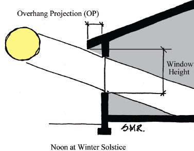
Fig. 4.6A. A winter-sun-side roof overhang allowing winter sun exposure for a window at 32˚ latitude
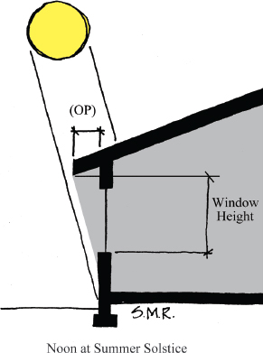
Fig. 4.6B. A winter-sun-side roof overhang providing summer shade for a window at 32˚ latitude
Given your latitude, how far should window overhangs extend out from a building’s winter-sun/equator-facing side? Here are two ways to figure it out.
One is with an equation. The other is with a to-scale drawing.
The equation way
The following equation is from The Passive Solar Energy Book by Edward Mazria.4 (Note that the equation only applies to equator-facing windows.)
window ÷ height F = Overhang Projection (OP)
Window height is determined by measuring the vertical distance from the windowsill to the bottom height of the overhang’s extension (see figure 4.6), while F is a factor selected from the table in box 4.3 according to your latitude and climate. (Note: If you will be installing gutters, be sure to include their width as part of the overhang’s extension, since they will extend the overhang and the shadow it casts.)
Box 4.3. Latitude and F factor
|
North or South Latitude |
F factor |
|
28˚ |
5.6–11.1 |
|
32˚ |
4.0–6.3 |
|
36˚ |
3.0–4.5 |
|
40˚ |
2.5–3.4 |
|
44˚ |
2.0–2.7 |
|
48˚ |
1.7–2.2 |
|
52˚ |
1.5–1.8 |
|
56˚ |
1.3–1.5 |
Using lower F factors provides more shade for more of the summer. Those living in a climate of hot summers and mild winters will likely want to use the lower number in the F factor range when calculating overhang length; those living in climates of mild summers and cold winters will likely want to use the higher number in the F factor range.
The to-scale drawing way
This method is my favorite because I can see more exactly where the sun and shadows will be any time of the year, and I can quickly adjust proposed overhang/ awning and window placements with pencil and eraser as needed.
Draw your building to scale.
Then look up your sun’s location above the horizon (known as its altitude angle or elevation angle) at solar noon on both the winter solstice and the summer solstice (see figures 4.7A and 4.7B). You can look up the sun’s altitude angle for your site based on the closest latitude to your site in box 4.2, the sun path diagrams in appendix 7, or you can calculate it using the following two equations (in which 23.44˚ is the earth’s declination or tilt):
• summer solstice noon altitude angle = 90˚ – (latitude + 23.44˚)
• winter solstice noon altitude angle = 90˚ – (latitude – 23.44˚)
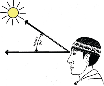
Fig. 4.7A. Altitude or Elevation Angle for the noonday sun’s location above the equator-side horizon on the winter solstice at 32˚ latitude is 35˚. (see box 4.2).
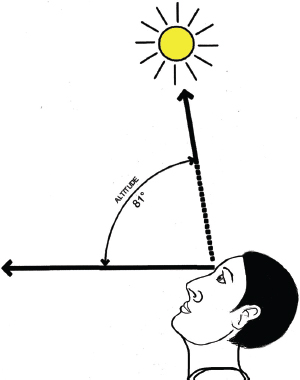
Fig. 4.7B. Altitude or Elevation Angle for the noonday sun’s location above the equator-side horizon on the summer solstice at 32˚ latitude is 81˚.
Conduct a web search for “latitude and longitude for your city and state” to find your site’s latitude in decimal format. For example, 32.22˚ is Tucson, Arizona’s, latitude.
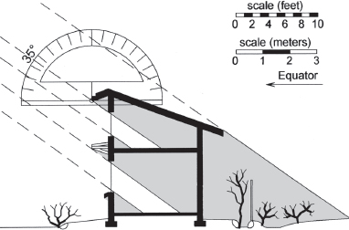
Use a protractor to draw those sun angles as they relate to key design elements (overhangs/awnings, window frames) that might block the direct sun (figures 4.8A and 4.8B). Aim for overhang/awning lengths and window sizes and placements that allow the maximum amount of direct sun through the equator-facing windows in winter (unless you’re in the hot, wet tropics where you don’t need winter heat), while shading out the sun in summer. Try moving different elements by extending, shortening, raising, or lowering the overhangs/awnings, and/or raising or lowering windows or making them taller or shorter to get the desired effect.
Fig. 4.8A. Winter solstice sun, heat, and light access illustrated with a to-scale drawing for 32˚ latitude. The lower awning is easier to access, is adjustable, and is retracted during the cold season to let in more sun and warmth.
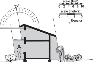
Fig. 4.8B. Summer solstice shade and cooling illustrated with a to-scale drawing for 32˚ latitude. The lower, adjustable awning has been extended to maximize shade for the hot season.
For video of this awning see SunAndShadeHarvesting.com
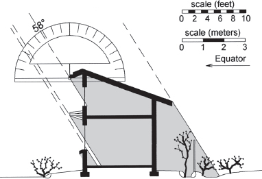
Fig. 4.8C. To-scale drawing for spring equinox. Temperatures are quickly warming up at this 32˚ latitude site, so less direct solar exposure is needed than in winter, but some direct passive heating is still provided by keeping the lower overhang retracted. Those in colder climates would want to design for more direct solar access.
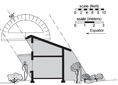
Fig. 4.8D. To-scale drawing for fall equinox. Temperatures are typically 20˚ to 30˚F (11˚ to 16˚C) warmer than at the spring equinox (see fig. 2.7 for equinox temperature fluctuations in Tucson, Arizona). This 32˚ latitude site experiences hot summers that linger into fall, so the lower awning is kept extended to provide needed shade and cooling.
For solar design software that does this, see the Sun Angles and Passive Solar Design section of appendix 6.
Refine your drawing/design further by adding the sun’s noonday altitude angle for the spring and fall equinoxes (March 21 and September 21).
You can use the following equation in which 0˚ is the earth’s equinox declination or lack of tilt:
• spring/fall equinox noonday altitude angle = 90˚ – your latitude
Aim to shade most or all of the equator-facing windows on spring and fall equinoxes in climates where ambient temperatures are hot on those days. Let most of the sun through the windows in climates where ambient temperatures are cold on the equinoxes.
Note that in many areas there can be up to a 30˚ F (16˚ C) difference in average temperatures between the spring and fall equinoxes, with the spring equinox much cooler than the fall (see figure 2.7 for an example of this in Tucson, Arizona). Retractable winter sun- or equator-side overhangs, awnings, or exterior sunscreens can be very useful to adjust sun exposure for the seasons. (See figures 4.8A, 4.8B, 4.8C, and 4.8D where the upper overhang is fixed because it is difficult to reach, but the lower overhang/ awning is seasonally adjustable.) Trellised winter-deciduous vines can be trained to approximate the same effect.
Passive heating and cooling ranges from low-cost to free. Overhangs, awnings, and vegetation screens consume no power or off-site water, create no pollution, and make no noise. They can be enhanced further with curtains or blinds opened when you want free daylight and heat, or closed if you want to deflect heat on hot days or to hold in warmth on cold nights. Likewise, fully operable windows can be opened or closed for ventilation and to function as inlets and outlets for indoor or outdoor warmth or cooling. These practices enable you to sail your home like a ship in winds of free on-site resources.
See the real life example in chapter 5 describing how my brother and I applied these features at our site. To maximize potential further, read box 4.4 to choose the right windows, and box 4.5 to size your windows for best performance in your climate. If you want still more, see the Sun Angles and Passive Solar Designs section of this book’s resource appendix 6 at HarvestingRainwater.com for information about additional strategies at the building, neighborhood, and city scale.
Box 4.4. Window Choices Dramatically Affect Passive/Free Heating and Cooling
The wrong window choice can dramatically diminish passive heating and cooling potential even if your building is oriented perfectly and has ideal overhangs. I’ve stood in the full winter sun on the inside of equator-facing windows and felt no heat. The problem is the use of inappropriate low-emissivity (low-E) windows.
Low-E glazing/windows have a transparent film that reduces heat flow through the glass by reflecting radiant heat back in the direction it came from. The enhanced insulation qualities of these windows can hold onto heat generated inside a building, but they also keep out radiant heat from the winter sun.
Some low-E windows are designed to allow higher solar heat gain for passive heating. However, these are hard to find because most manufacturers and builders focus on conserving energy by using higher reflection-value windows. This approach ignores the potential to integrate energy conservation and energy production through lower reflection-value, equator-facing windows that harvest winter heat.
Before installing any equator-facing window, check its National Fenestration Rating Council (NFRC) sticker, which lists its transmittance characteristics. Beware of salvaged windows that may no longer have NFRC stickers. If a window is being installed facing the equator with the goal of achieving passive solar heating, the window must meet the following criteria:
• A Solar Heat Gain Coefficient (SHGC) greater than 0.60. The higher the number (1 is the highest), the greater the solar gain.
• A U-factor rating of potential heat loss of 0.35 or less. The lower the number, the better the window keeps heat inside.
• A Visible Light Transmittance (VT) greater than 0.65.5 Below 0.40 is considered a tinted window.
To achieve maximum passive heating potential for my projects in the southwest U.S. that have well-designed overhangs, I’ve chosen operable, non-low-E, untreated, clear double-glazed or double-paned windows for all equator-facing windows. To achieve maximum insulation value for windows facing all other directions, I’ve chosen operable, double-glazed low-E windows. To reduce loss of heat on winter nights through the non-low-E windows I do not install an excessive amount of equator-facing glass (see box 4.5) and I close curtains over these windows nightly in winter then open the curtains in the morning.
Whatever the coating (or lack of it) on your glass, don’t overlook your window’s ventilation potential. Choose operable windows you can open and close to let in warmer or cooler outside air as needed. The window section of appendix 5 expands on this further, while appendix 8 shows you how you can direct or divert more air flow in and out through your windows.
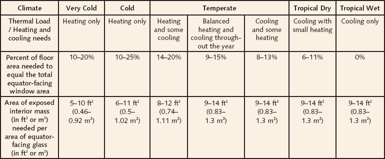
Box 4.5. Size Your Equator-Facing Windows to Maximize Free Heating and Cooling
For buildings in various climates using direct-gain/distributed mass systems, the table below gives you guidelines on optimal equator-facing window surface areas and optimal interior mass surface areas to reduce daytime overheating and nighttime overcooling.
Direct-gain buildings use the direct entry of winter sun coming through equator-facing windows to heat the interior space and the mass within. Thermal mass absorbs and holds heat, reducing interior temperature fluctuations.
Distributed mass is thermal mass that is distributed throughout a large interior area in the form of exposed concrete, masonry, earth, or stone floors (which work best if insulated from the earth below), walls, and plasters (which work best if insulated from the exterior). Low-mass gypsum plaster or wallboard can even be used as distributed mass when installed in two 5/8-inch (15-mm) thick layers, but due to its lower ability to store heat, divide that wallboard area by 4 when determining area of mass per area of equator-facing window (aperture) in the table below.6
Examples following the table illustrate how to use it.
Table reprinted with permission from Passive Solar Architecture: Heating Cooling, Ventilation, Daylighting, and More Using Natural Flows by David A. Bainbridge and Ken Haggard, Chelsea Green Publishing, 2011.
I redesigned an old 200 ft2 (18.5 m2) cinderblock one-car garage into a direct-gain/distributed mass “cottage” that I now call a “garottage.” Using the table above, I calculated its direct-gain/distributed mass window area as follows:
• I live in a climate where homes typically need cooling and some heating. According to the table, this requires a total equator-facing window area 8–13% of the floor area.
• My garottage floor area equals 200 ft2 (18.5 m2), and I used 12% of my floor area as my window area goal. So, 200 × 0.12 = 24 ft2 (2.2 m2) of needed equator-facing window area is needed.
I attained this using
- One 2.5’ × 3.5’ window = 8.75 ft2 (0.81 m2)
- One 1.5’ × 3’ door window = 4.5 ft2 (0.41 m2)
- Two 2.3’ × 2.3’ windows = 10.58 ft2 (0.98 m2)
- Total equator-facing glass = 23.83 ft2 (2.2 m2)
Note: I only measured the actual area of glass, and did not include any part of the windows’ frame or sash.
According to the table, the recommended area of interior mass for my site is 9–14 ft2 (0.8 –1.3 m2) of mass / ft2 (m2) of equator-facing window area. Within the range, I used 14 ft2 (1.3 m2) so my goal was 14 × 23.83 = 333.62 ft2 (in metric, 1.3 × 2.2 = 2.86 m2) of needed exposed interior mass.
I exceeded that with the interior exposed cinder block wall area minus the area of windows, doors, cabinets, etc. = 343 ft2 (3.8 m2) of mass. The cinder block wall was exsulated—insulated on the exterior.
A thermally exposed concrete floor slab (uncovered by carpet, closets, etc.) could count as more mass, but it would ideally be insulated from the ground below in my climate, and in colder climates must be insulated in order to count as thermal mass.
If I had installed 5/8-inch (15-mm) gypsum plaster or wallboard two-layers thick over framed insulated walls, I could have counted that 359 ft2 (33.3 m2) of exposed wallboard area as mass. However, due to its lower ability to store heat, I would have to divide the wallboard’s area by 4 (359 ÷ 4 = 89.75 ft2 [or 8.3 m2] of mass). That’s not enough mass by itself, but if I added 200 ft2 (18.5 m2) of thermally exposed concrete slab floor, I would attain 12 ft2 (1.1 m2) of exposed interior mass per 12 ft2 (1.1 m2) of equator-facing glass—well within the recommended range.
See more on the garottage in the Real Life Example of chapter 5.
Overhangs for Gardens
Here in the low desert of southern Arizona, living overhangs can allow entry of low-angle winter sun while creating diffuse summer shade, conditions that vegetable gardens crave. To accomplish this, dig sunken garden beds under winter-deciduous, nitrogen-fixing, native mesquite trees (Prosposis velutina) that allow winter sun into the garden and place your more sun-loving plants in the south and southeast beds. Using this layout, I can harvest salad greens, artichokes, herbs, snow peas, garlic, onions, potatoes, carrots, Jerusalem artichokes, and edible flowers throughout the fall, winter, and spring. In the extreme heat of summer when evapotranspiration rates increase, the diffuse shade of the mesquite’s overhanging branches keeps the chiles, tomatoes, basil, eggplant, squash, gourds, and summer greens from prematurely wilting from exposure.
Action Steps
• Shut off mechanical heating and cooling systems once in each season of the year to observe how direct solar exposure—or the lack of it—affects the comfort of your home. Don’t do this, however, when indoor pipes could freeze (perhaps due in part to poor winter sun exposure).
• Use the overhang projection calculation or to-scale drawing method to determine the appropriate overhang sizes for your area. Compare the existing overhangs to what the calculation or drawing recommends. Observe how the overhangs affect your comfort.
• When installing or extending an overhang, consider the following options:
- An overhang extending across the whole summer-sun-side (equator-facing side in latitudes above 23.5˚ latitude, or the side opposite the equator in latitudes below 23.5˚ latitude) of your building to benefit your wall as well as your windows.
- Awnings for your summer-sun-side windows and/or wall (fig. 4.9).
Fig. 4.9. Window awning shading/cooling windows and wall in summer
- A seasonally retractable/extendable summer-sunside awning (see figures 4.8A through 4.8D)
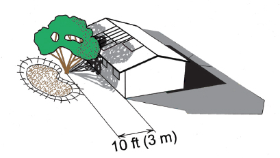
• Consider a very sparse trellis to support dense winter-deciduous vines which will provide leafy shade in summer. (See figure 4.10.) In the winter, remove and mulch the uppermost sections of the leafless vines so your windows get direct winter sun (see “Integrated Design Pattern Five: Maintaining Winter Sun Access”). Use rooftop runoff to irrigate the vines. (Note: While water-harvesting earthworks should be placed a minimum 10 feet (3 m) from the house, vegetation can be planted closer to a building. Just train the roots of the plants to find the water harvested in the more distant earthworks. Do this by applying irrigation water on the side of the plant closest to the earthworks. Then every month or two in the growing season move your irrigation emitter or hose a foot further from the plant and a foot closer to the earthworks, until you eventually end up watering the plant via its extended roots within the earthworks.)
Fig. 4.10A. Winter-sun-side trellis in summer
Fig. 4.10B. Sparse winter-sun-side trellis in winter
• Position exterior blinds or shutters on east- and west-facing windows to help block direct summer sun before it enters and heats the building (fig. 4.11).
Fig. 4.11. East-facing exterior blinds doubling as pollinator habitat. Beneficial carpenter bees live in the hesperaloe flower stalks of which the blinds are made. Note dappled shade from trees to east provides additional cooling!
• Install covered porches and/or shade trees on the east, west, and summer-sun sides of your building as presented in the next pattern.
• Aim to design, purchase, retrofit, rent, or use buildings in which equator-facing rooms have appropriately sized equator-facing window(s) (box 4.5) based on the building’s floor area and winter heating needs. In addition, make sure the rooms that are used most during the day are located on the winter-sun- or equator-facing side of the building for passive winter heating and lighting. Night-use bedrooms should be placed on the winter-shade-facing side of buildings, since blankets and others can warm you.
INTEGRATED DESIGN PATTERN THREE
SOLAR ARCS
A solar arc is created using a number of shading elements such as trees, cisterns, trellises, covered porches, and overhangs laid out in a C-shape, like that of a big open-armed hug that welcomes the full potential of the winter sun (fig. 4.12). At the same time, it deflects much of the summer sun using the arc’s “back, shoulders, arms, and hands.” Water-harvesting earthworks are the foundation of solar arcs when vegetation is used as the sheltering element (figure 4.13 shows the growth of the solar arc from basin to young trees to mature trees). Situate the earthworks and trees close enough to buildings to use roof runoff as the primary source of irrigation water and household grey-water as the secondary source. As the shade trees grow they beautify your yard, clean the air, and dramatically cool summer temperatures (see boxes 4.6 and 4.7).
Fig. 4.12A. Solar arc of trees with an east-west oriented building at 32˚ N latitude. View of building’s winter-sun side. Roof-mounted solar panels and solar water heater receive full sun all year round. Winter-deciduous trees on the east and west sides of building expose it to more winter morning and afternoon heat and light than evergreens would. Compare to figure 4.5A.
For video of this see SunAndShadeHarvesting.com.
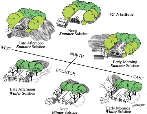
Fig. 4.12B. Solar arc of trees with a north-south oriented building at 32˚ N latitude. View of building’s winter-sun side. Solar panels are mounted on a special sun-tracking rack on south-side of trees to receive full sun all year round. Winter-deciduous trees on the east and west sides of building expose it to more winter morning and afternoon heat and light than evergreens would. Compare to figure 4.5B.
Fig. 4.13A. Water-harvesting basins placed to help grow a solar arc of trees, and one basin on the winter-sun side of the house to grow a sunken winter garden (32˚N latitude)
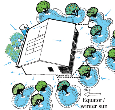
Fig. 4.13B. Young trees and the garden planted within the basins and irrigated with harvested roof runoff. Dotted lines represent supplementary greywater lines. Greywater is directed to fruit trees where people gather for convenient irrigation and fruit harvest.
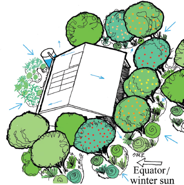
Fig. 4.13C. Trees at full size forming a living solar arc, and a thriving winter garden. Solar panels and solar water heater have full access to sun all year.
Box 4.6. “Cool and Clean” or “Cool and Polluted”
The generation of electricity used to mechanically air condition an average household causes about 3,500 lbs (1,587 kg) of carbon dioxide and 31 lbs (14 kg) of sulfur dioxide to be released from powerplant smoke stacks each year.7 Cooling solar arcs of trees consume carbon dioxide and produce oxygen—up to 5 lbs (2.2 kg) of oxygen per day per tree.8 According to the National Arbor Day Foundation, over a 50-year period, a well-placed shade tree can generate $31,250 worth of oxygen and provide $62,000 worth of air pollution control.8
Search “the value of trees” online for additional benefits.
Box 4.7. Growing Your Air Conditioner
A study conducted in Phoenix, Arizona found that water use in evaporative coolers averages 65 gallons (246 liters) per cooler per day, or about 13,400 gallons (50,725 liters) during the cooling season from March to October.9 That same amount of water could fulfill all the water needs of four native mesquite trees with 20-foot (6-meter) heights and canopies.10 If placed on the east, west, northeast, and northwest sides of a home, these shade trees could reduce summer temperatures around the building by as much as 20˚F (11˚C) compared to the same building without shade.11
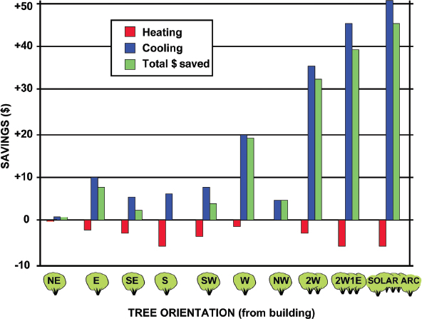
Another study found that just three winter-deciduous, 25-foot (7.6-m) tall and 25-foot wide trees (two west of a house, one on the east) reduced annual energy use for cooling by 10 to 50% and reduced peak electrical use up to 23%, without shading equator-facing windows and adversely increasing winter heating needs.12 A solar arc of trees can boost these benefits further (see figure 4.14).
Fig. 4.14. Place trees wisely. Graph illustrates annual heating, cooling, and total energy use differences (energy savings are positive, energy use increases are negative) for an east-west oriented building in Sacramento, California, based on placement of adjoining winter-deciduous trees. Savings are expressed as a percentage of energy (kWh) saved for a shaded building compared to an unshaded building, with single shade trees located at cardinal (E, S, W) and inter-cardinal (NE, SE, SW, NW) points around the building. Results are also given for two west shade trees combined with one east shade tree (2W1E), and for a solar arc of trees—one east, one northeast, one northwest, and two west, but NO trees to south (SOLAR ARC). Note how a misplaced shade tree on the south side can result in heating increases that offset cooling savings (this increases in cooler/colder climates). Adapted from “Potential of Tree Shade for Reducing Residential Energy Use in California” by James R. Simpson and E. Gregory McPherson, Journal of Arboriculture 22(1), 1996
Solar arcs shade buildings, gardens, and gathering spots in the yard from the summer’s northeastern morning and southwestern afternoon sun. Put trees that drop their leaves in winter on the east and west arms of the arc to allow filtered sun to penetrate the arc early in spring and late into fall. Evergreen trees work well on the northern band of the arc to block summer sun and deflect cold northerly winter wind. The same principle works in the southern hemisphere, only the directions change.
Action Steps
• See if you have any elements of a solar arc in place around your home or garden, such as an existing shade tree or building.
• Map where missing pieces of a solar arc should be located to complete it and benefit your home or garden. Create water-harvesting earthworks and/or install cisterns to sustain shade trees.
• Consider a design for layers of solar arcs. One layer can be close to the house to shelter the house. The next layer can be along the fence line of the yard to shelter the yard, you outside, tender veggies, or fruit trees planted within the arc. The further you are from the house and its resources (roof runoff, greywater, caregivers living in the home) the hardier (more drought-, heat-, and cold-tolerant) the arc’s plant species should be. Typically hardy native perennials are best for the peripheral arc.
INTEGRATED DESIGN PATTERN FOUR
SUN & SHADE TRAPS
A sun & shade trap creates a nice place to plant a garden or take an outdoor nap. Elements making up this trap can include cisterns, tall low-water-use vegetation, a house, trellis, shed, or other shading elements. A sun & shade trap is more open to the morning sun than a solar arc. In the northern hemisphere the L-shaped trap is open to the east and south, and closed to the north and west. In the southern hemisphere it is open to the east and north, while closed to the south and west. (See figure 4.15.) The sun & shade trap creates microclimates ideal for gardens, sensitive plants, cozy outdoor gathering areas, and hammock roosts.
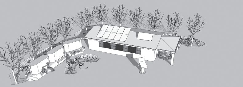
Fig. 4.15A. House, cisterns, and trees at 32˚ N latitude form a morning sun trap for the sunken garden, cistern benches, and solar oven; while house and trees form a second sun trap for the east-facing porch at 9 A.M. on the winter solstice when the sun’s warmth and light are desired. The solar oven is facing the sun.
Note how the building’s orientation to sun, and roof overhangs also optimize winter sun access to its equator-facing windows and trombe walls (square black sections of wall between the windows).
Illustration made with the free version of Sketch Up program, a handy tool for representing sun angles and shadow lengths for any inputted date and time.
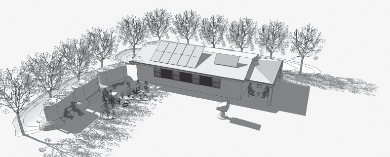
Fig. 4.15B. Same house, cisterns, and trees form an afternoon shade trap for the sunken garden and cistern benches; while house and trees form a second shade trap for the porch at 4 P.M. on the summer solstice when cooling shadows are desired on hot afternoons. The solar oven is facing the sun.
Note how the building’s orientation to sun, and roof overhangs also optimize summer shade access to its equator-facing windows and trombe walls.
The sun & shade trap effect illustrated in these two figures works every day of the year, with sun and shadow angles changing seasonally. In climates or situations where more shade is desired, particularly in the morning, the solar arc pattern could be used instead of the sun & shade trap pattern.
Box 4.8. Sun & Shade Trap Cisterns Acting as a Windbreak, Firebreak, Sun Screen, Privacy Screen, Property Fence, and Economic Stimulus
Creating myriad beneficial relationships (the seventh water-harvesting principle) make static cisterns dynamic. Thus the cisterns in figures 4.16A, 4.16B, and 4.16C were selected and placed to transform them into much more than water tanks. We selected and purchased locally made tanks to strengthen our local water-harvesting economy. Then we placed the tanks on our western property line to act as a section of property fence. In this location the tanks deflect hot, dry prevailing winds from the southwest; shade the garden and a seating nook from the hot afternoon sun; give our neighbors and ourselves a privacy screen; and serve as a sound-deflecting, concrete, water-filled firebreak.
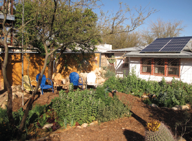
Fig. 4.16A. 9 A.M., garden sun trap, Lancaster residence, Tucson, Arizona, February 22. In cold morning hours, the winter garden and the home’s equator-facing windows and solar panels are in full sun to quickly warm up, grow crops, and produce energy.
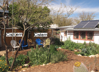
Fig. 4.16B. Noon, garden sun trap, Tucson, Arizona, February 22. As temperatures have warmed up, winter garden is still largely in direct sun, though the leafless winter-deciduous mesquite tree casts some diffuse shade over a third of the garden. The sun has set on the east face of the two 1,300-gallon (4,920-liter) ferrocement cisterns behind the chairs west of the garden.
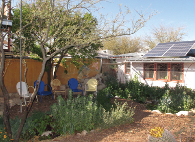
Fig. 4.16C. 3 P.M., garden shade trap, Tucson, Arizona, February 22. During the hottest hours of the day, the winter garden is in the cool shade cast by the sun & shade trap created by the cisterns, orange tree, and ramada/shade structure (the northeast corner of which is showing in the upper left corner of the photo) west of the garden. This shading reduces the plants’ heat stress and evapotranspiration, making the sole source of water—harvested rainwater—go further.
My sun & shade trap captures winter sun in the mornings to burn off frosts and warm things up, but shades out sun on hot afternoons. This extends the cool growing season of my low desert garden by two months. I can plant a month earlier and get an extra month of growth by keeping my vegetables from bolting (going to seed). The afternoon shade reduces plant evapotranspiration, heat stress and drought stress, and reduces pest problems. I enjoy hanging out in my sun & shade trap garden, because, like the plants, I get warmth in the morning when I want it, and shade in the afternoon when I need a break from the sun.
Action Steps
• Before you plant, identify and map the areas of your site where a sun & shade trap might make sense, and map any existing elements already in place.
• Harvest rainwater to support vegetative elements in the sun & shade trap. As Mr. Phiri says, “Plant the water before you plant the trees.”
• Determine if a new cistern could be placed to help create a sun & shade trap for a garden or patio.
INTEGRATED DESIGN PATTERN FIVE
MAINTAINING WINTER SUN ACCESS
Just as you harness the full potential of the rain, do the same for the winter sun in order to reduce your energy consumption and simultaneously reduce water consumed to generate that energy (as explained in appendix 9). Keep solar exposure open for winter sun-facing windows, gardens, solar water heaters, solar panels, and solar ovens. The Village Homes development in Davis, California, found that with winter solar access retained, simple solar homes can achieve 40 to 50% of their winter heating needs from the sun, while more sophisticated designs can meet 85% of their heating needs.13 I rely on south-/equator-facing windows for most of my home’s heating needs. A solar water heater provides all my hot water and ten solar panels provide all power needs. But misplaced trees could seriously cripple this performance since even the shadow cast by a leafless tree could block out over 50% of the potential heat and light (see figures 4.17A and 4.17B).14
Fig. 4.17A. Majority of winter solar access lost.
At 32˚ latitude from 9 A.M. to 3 P.M. on the winter solstice, a misplaced mature evergreen tree blocks winter sun exposure for winter-sun/equator-facing windows and rooftop solar water heater and solar panels. Shadows are shown as gray for 9 A.M. and 3 P.M.
Solar noon shadows are black.
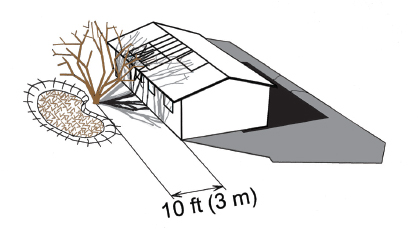
Fig. 4.17B. Over half of winter solar access lost. At 32˚ from 9 A.M. to 3 P.M. on the winter solstice, the bare branches of a misplaced mature deciduous tree shade out over 50% of winter sun exposure, increasing heating costs and severely hampering solar power production.
When planning where to place above-ground cisterns or trees, and the water-harvesting earthworks that will sustain them, be conscious of the shadows they will cast. Place them an appropriate distance from the house so they won’t block the winter-sun/ equator-facing side of your home, solar water heaters, and solar PV panels (figures 4.17C and 4.17D). Placed even farther from the house, they will allow access to all of the above plus to lower-elevation trombe walls, solar hot air collectors, solar ovens (figures 4.17E and 4.17F), winter gardens, and solar greenhouses/cold frames.
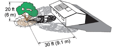
Fig. 4.17C. Winter solar access retained. At 32˚ latitude from 9 A.M. to 3 P.M. on the winter solstice, an evergreen tree planted sufficiently far from the house, so solar access is retained from the bottom of the winter-sun/equator-facing windows up to the equator-facing slope of the roof. See box 4.9 to estimate winter-shadow lengths.
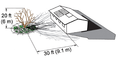
Fig. 4.17D. Winter solar access retained. At 32˚ latitude from 9 A.M. to 3 P.M. on winter solstice, a winter-deciduous tree lets more warming winter light onto the ground than an evergreen tree, while creating better growing conditions for a winter garden beneath the tree.
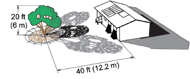
Fig. 4.17E. Winter solar access retained for entire winter-sun/equator-facing wall, solar oven, solar hot air collectors beneath windows, and roof at 32˚ latitude
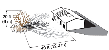
Fig. 4.17F. Winter solar access retained for entire winter-sun/equator-facing wall, solar oven, trombe walls beneath windows, and roof at 32˚ latitude. If you miscalculate the distance of the tree from the building, a winter-deciduous tree will not be as bad as an evergreen.
Winter solstice shadow ratio: determining shadow lengths
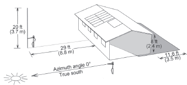
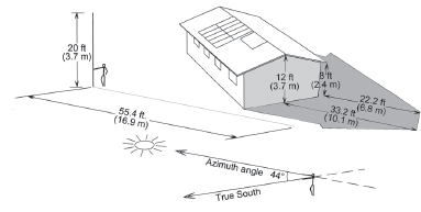
You can determine the longest shadow an object will cast on the winter solstice (December 21 in the northern hemisphere, June 21 in the southern) by looking up your latitude in box 4.9, and multiplying the object’s height by the associated factor of the winter solstice shadow ratio. For example, at 32˚ N latitude the solar noon ratio is 1:1.45, so for every foot (or meter) of an object’s height, the shadow cast at noon on December 21 will be 1.45 feet (or meters) long. Multiply the height of a mature 20-foot (6-m) tall tree by 1.45 to get 29 feet (8.7 m)—the length of the noonday shadow cast to the north at this latitude. (See figures 4.18A and 4.18B.)
Box 4.9. Winter-Solstice Shadow Ratios
Determine objects’ shadow lengths and direction on the day with the longest shadows of the year using the following shadow ratios and the sun’s azimuth angles for your latitude.
Use the ratio 1: × to get the length of the shadow cast by an object (tree, cistern, house) for each foot (or meter) of height. Multiplying the height of the object times × tells you the length of the shadow in feet (or meters). To get the direction of the shadow cast by an object, look at the Azimuth angle—the angle of the sun’s location east or west of True South in the northern hemisphere or of True North in the southern hemisphere. (See figures 4.19 and 4.20.)
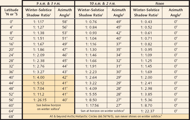
Noon is solar noon, 9 A.M. & 3 P.M. are 3 hours before & after solar noon, 10 A.M. & 2 P.M. are 2 hours before & after solar noon.
Azimuth angle: Degrees sun is east (A.M.) or west (P.M.) of due south (in northern latitudes) or due north (in southern latitudes) on winter solstice at given times. Azimuth angle is 0° at all latitudes at solar noon on all dates.
Winter-solstice shadow ratio: Ratio of an object’s height to the length of its shadow cast on winter solstice at given times.
Winter-solstice shadow ratios and azimuth angles for (10 A.M. & 2 P.M.) are more important at higher latitudes where shadows are longer, and 9 A.M. & 3 P.M. sun access is less likely to be practical compared to lower latitudes.
For shadow ratios and azimuth angles for every degree of latitude see Winter-Solstice Shadow Ratio & Azimuth Table on the Sun & Shade Harvesting page at HarvestingRainwater.com.
1. Shadow ratio = 14 tangent of altitude angle.
At noon on the winter solstice, the altitude angle = 90° – (latitude + 23.44°).
2. http://www.esrl.noaa.gov/gmd/grad/solcalc/, accessed 7/5/2012
3. http://en.wikipedia.org/wiki/Arctic_Circle, accessed 7/16/2012
Fig. 4.18A. Using the winter-solstice noon shadow ratio of 1:1.45 for 32˚ N latitude from box 4.9 to determine length of solar noon shadows cast, multiply mature tree height of 20 ft (6 m) by 1.45 = solar noon shadow length of 29 feet (8.7 m). Stand at proposed tree location (with or without a pole as tall as proposed tree height) and walk off its estimated shadow length to determine where the tree will or will not adversely shade the building.
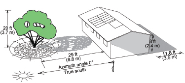
Fig. 4.18B. Shadows cast at noon on winter solstice at 32˚ N latitude once tree reaches mature size. For video of this see SunAndShadeHarvesting.com.
Shadow ratios for the benchmark times of solar 9 A.M. and 3 P.M. are given. Since the sun is much lower in the sky at these times, the shadows will be much longer than those at noon. The hours between 9 A.M. and 3 P.M. are ideal for winter sun access for passive heating, solar cooking, producing solar power, and solar heating of water. Before 9 A.M. and after 3 P.M. the potential use and efficiency of the sun is greatly reduced since the sun is lower in the sky, resulting in its rays traveling through more heat- and light-diffusing atmosphere.
Shadow ratios are also given for the hours of 10 A.M. and 2 P.M. in box 4.9 for higher latitudes with longer winter shadows where the challenge of maintaining solar access increases, particularly in dense urban settings. Due to this increased challenge, some solar rights requirements—such as the Living Building Challenge Imperative 18: Rights to Nature—only require direct solar access to be maintained between these winter solar hours.15 Interestingly, research has found that solar zoning maintaining this type of winter solar access does not reduce desired high urban densities.16
Azimuth: determining sun and shadow angles
The sun’s Azimuth angle—the angle of the sun’s location east or west of True South in the northern hemisphere or of True North in the southern hemisphere—is also given in box 4.9, since shadows are cast in the opposite direction of the Azimuth. For example, at 32˚ N latitude at noon, the Azimuth is 0˚, so the sun is due True South and the shadow will be cast due True North. While at 3 P.M., the sun is 44˚ west of True South, so the shadow will be cast 44˚ east of True North at that time. (See figures 4.19 and 4.20.)
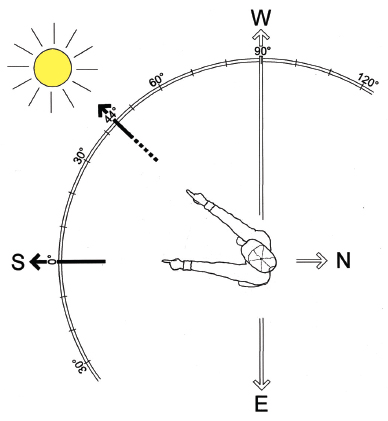
Fig. 4.19. Azimuth angle of the sun at 3 P.M. on the winter solstice at 32˚ N latitude. The Azimuth is the sun’s location in degrees east or west of True South in the northern hemisphere or of True North in the southern hemisphere.
Fig. 4.20A. Using winter-solstice 3 P.M. shadow ratio of 1: 2.77 from box 4.9 to determine length of shadow cast at 32˚ N latitude, and using Azimuth angle of sun’s location from True South to determine direction of shadow
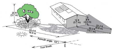
Fig. 4.20B. Shadows cast at 3 P.M. on winter solstice at 32˚ N latitude once tree reaches mature size
Using the shadow ratios and azimuth angles in box 4.9 you can determine how far away from your home in the direction of the equator and winter sun you need to place that tree (or an above-ground cistern or proposed building) so it won’t block needed winter solar access once it grows to mature size.
Action Steps
• Use the shadow ratio in box 4.9 to predict how existing vegetation and structures might affect your (and your neighbor’s) winter solar gain. Then observe what happens.
• Use the shadow ratio calculation to correctly place new structures or vegetation on the winter-sun side of your buildings or winter garden. Plan for plants’ sizes at maturity, not the size at planting time. Consult nursery staff and plant books for size information.
• Plan water-harvesting earthworks and cistern systems to support correctly placed vegetation.
Box 4.10. Solar Access, Easements, and Rights
Solar rights are the right to access and harness the rays of the sun.17 These rights must be maintained for our neighbors and ourselves so we can passively heat and light and freely power the spaces where we live, play, grow food, and work in regenerative non-polluting ways.
In 1977, the State of New Mexico enacted the Solar Rights Act, the first law in the country recognizing the natural resource of solar energy as a property right. The property owner who first claims solar rights can prevent neighboring property owners from encroaching upon the right or easements with new buildings or trees.
In Arizona, Solar Rights Law ARS 33-439 has banned any covenant, restriction, or condition from prohibiting the installation or use of a solar energy device.
The progressive communities of Village Homes in Davis, California, and Milagro Cohousing in Tucson, Arizona, state in their Declaration of Covenants, Conditions, and Restrictions (CCRs) that residents are prohibited from interfering with a neighbor’s solar rights. A homeowner is, however, allowed to infringe on his or her own rights.18, 19 Rather than banning the use of solar clothes dryers (clothes lines) as some CCRs do, they encourage their use.
See the Solar Access, Solar Easements, and Solar Rights section of the resource appendix on my website for more information, including how architect Ralph Knowles (through a solar zoning of “solar envelopes”) and others show how solar rights can be retained throughout whole cities without adversely reducing density.
See chapter 5 for how we maintained solar access for ourselves, and our neighbors (figures 5.12A and B), while practicing solar rights for the larger community.
Box 4.11. Pruning for Winter Sun
If you currently have mature trees blocking your winter heat and light you can prune them to regain winter solar access. Use box 4.2 to determine what part of the sun’s path you could reopen with pruning, then prune if appropriate; see also figure 4.21.
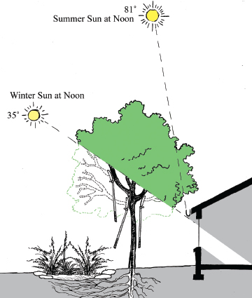
Fig. 4.21. A tree pruned to allow direct winter sun access through winter-sun/equator-facing windows, while shading out the summer sun at 32˚ latitude Adapted from Designing and Maintaining Your Edible
Landscape—Naturally by Robert Kourik, Metamorphic Press, 1986
INTEGRATED DESIGN PATTERN SIX
RAISED PATHS, SUNKEN BASINS
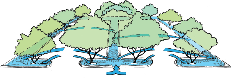
Keep access ways “high and dry” and planted areas “sunken and moist.” Always pair a raised path with a sunken basin to capture runoff and grow shelter and beauty for the path (fig. 4.22). Trees planted in these water-harvesting basins shade and beautify the adjacent roadways, paths, and patios. This reduces excessive solar exposure and in turn the risk of skin cancer, the fastest growing form of cancer in the United States,20, 21 while creating a comfortable place to drive, walk, ride a bike, or converse. In cold climates raised paths and roads also help keep them ice free.
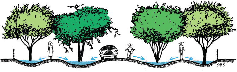
Fig. 4.22. Raise pathways, and sink mulched and vegetated basins.
Shade trees absorb much of the rain falling within the diameter of the tree canopy and runoff flowing around their bases. This creates a living flood control system and filters runoff-borne contaminants like nitrates, phosphorus, and potassium, which trees consider food.22
A parking lot can be planted with a “living carport” of flood-controlling, pollutant-filtering native shade trees irrigated solely by the parking lot’s runoff. If low-water-use food-producing trees such as the velvet mesquite are planted, it becomes a “parking orchard.” (See figure 4.23.)
Fig. 4.23. A parking orchard of low-water-use, food-producing shade trees passively irrigated by runoff from a raised parking area harvested within sunken, mulched basins.
Ideally, many perennial understory plantings are also included.
Action Steps
• Observe the relative height of paths, sidewalks, driveways and streets compared to adjacent planting areas in your home and community. Do you see the “raised path, sunken basin” pattern or a sunken path, raised planting area pattern? Is storm-water being directed to vegetation, asphalt, or storm drains?
• Observe undisturbed natural areas. You will most likely find the largest, densest vegetation in depressed areas and along drainages where water concentrates.
• Identify and map areas where you can develop the raised path, sunken basin pattern at home. Create water-harvesting earthworks by digging sunken basins, then use the newly available dirt to create the raised paths.
INTEGRATED DESIGN PATTERN SEVEN
REDUCE PAVING AND MAKE IT PERMEABLE
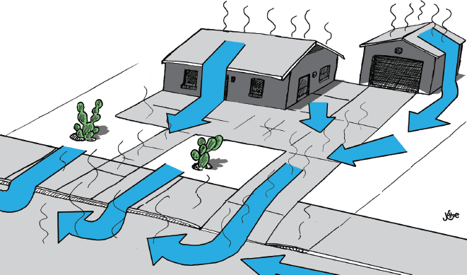
Rainwater is like a naked person—it won’t stick around if you put it on hot pavement in summer. So, we must reduce the amount of impervious paving on our sites and neighborhoods, while increasing shady vegetation (compare figures 4.24A and 4.24B).
Fig. 4.24A. A dehydrated and exposed residential lot dominated by impervious pavement, sparse vegetation, and bare compacted earth graded to drain all runoff to the street
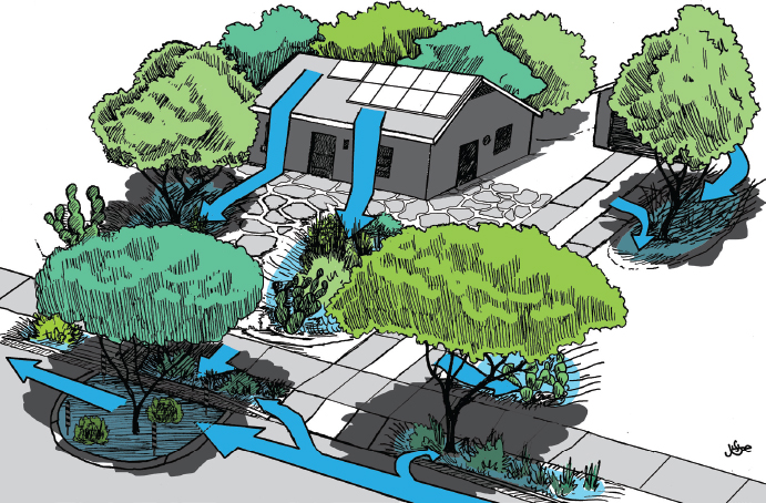
Fig. 4.24B. A hydrated and sheltered residential lot dominated by water-harvesting earthworks, native low-water-use vegetation, and permeable paving graded to minimize runoff and utilize it on-site. See figures 3.16 to 3.18 for more strategies.
Much of the heat stored in urban concrete and asphalt during the day is released in the late afternoon and evening, keeping temperatures high. Excessively wide, unshaded streets and dense unshaded development directly contribute to the heat island effect, and were found to raise maximum daytime temperatures by 10˚F (5.5˚C) in Davis, California.23 (See figure 4.25A for an example of a wide, tract-home street.)
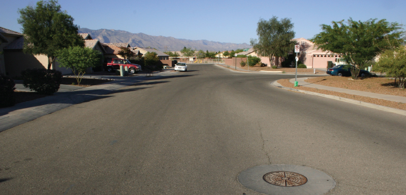
Fig. 4.25A. Creating the summer heat-island effect, which can increase temperatures by up to 10˚F (5.5˚C). A wide, exposed, solar-oven-like street in Tucson, Arizona. There are no trees in the public right-of-way.
Typical residential streets in the western U.S. are up to 40 feet (12.2 m) wide, but there are alternatives. At the innovative Village Homes housing development in Davis, California, streets are 20 feet (6.1 m) wide.24 By narrowing streets, using cul-de-sacs, and limiting driveways to the length of a vehicle, Village Homes made 15% more land available for community gardens, orchards, tree-lined walkways, and bike routes.25 Adjoining trees create a canopy over the narrow streets, shading 80% of the streets’ area, reducing summertime temperatures, reducing the need for buzzing air conditioners, and creating a much quieter and more pleasant neighborhood (fig. 4.25B).
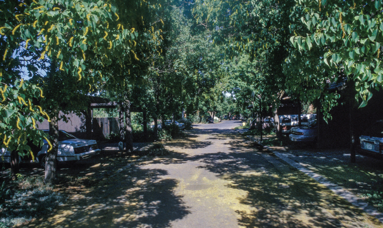
Fig. 4.25B. Creating the summer cool-island effect, which can reduce temperatures by up to 10˚F (5.5˚C). A narrow, mature tree-lined, and shaded street in Village Homes, Davis, California. Trees are planted in the public right-of-way just a couple of feet from street curb to shade more of the street. In winter these trees will drop their leaves to let in more heat and light when needed. See Fig. 3.17 for a narrow, tree-lined street in Tucson, Arizona. Compare to figure 4.25A
Direct street runoff to adjoining water-harvesting earthworks, try to reduce the amount of paving, and see if some of remaining pavement should/could be made permeable. In volume 2, the chapter “Reducing Hardscape and Creating Permeable Paving” features a number of permeable pavements that can reduce runoff by up to 90% and yield significantly cleaner stormwater compared to impervious pavements.26
Action Steps
• Look for examples of pervious and impervious paving around your home and community.
• Determine how you can reduce the paving on your site, and make remaining pavement more permeable. Implement these changes.
• Consider turning your driveway into a park-way by limiting its size to the length and width of your vehicle.
• Consider using porous brick, cobbles, or stabilized gravel in place of impervious paving materials.
• Plan water-harvesting earthworks and appropriate plantings in areas where paving is removed, and adjacent to areas where paving remains.
• Consider growing outdoor “rooms” of shade trees to replace or reduce the need for more buildings (fig. 4.26).
Fig. 4.26. Grow a classroom instead of building one, and grow an air conditioner instead of buying one. Admiring the birds in the canopy of oak trees forming a living, self-cooling outdoor classroom at the Wildflower Center in Austin, Texas
• Daylight or uncover buried waterways. Show the flow.
• In volume 2, read the chapter “Reducing Hardscape and Creating Permeable Paving.”
INTEGRATING THE ELEMENTS AND PATTERNS OF YOUR SITE TO CREATE A REGENERATIVE LANDSCAPE DESIGN
The preceding integrated design patterns should have you thinking about, mapping, and planning where you can lay out water-, sun-, and shade-harvesting strategies to create a more integrated, efficient, and productive design. These patterns are meant to give you a conceptual framework for creating “regenerative designs.” Regenerative designs arise from thoughtful integration of elements with natural local resource flows so they can enhance and recreate themselves without dependence on imported inputs such as piped-in fuel or pumped-in water. Once established, these regenerative designs do the bulk of the work, so you don’t have to. They maximize the return on your on-site resource-harvesting investments.
In order to continually progress your own understanding of what is possible through design, the following question and its three criteria are useful for assessing design success:
Are the elements, systems, and patterns of design relationships that you have created degenerative, generative, or regenerative? Compare their characteristics below, and apply these concepts to your thinking and design.
A degenerative investment:
• Starts to degrade or break down as soon as it is made;
• Requires ongoing investments of energy and outside inputs to keep it functional;
• Consumes more resources than it produces;
• Degrades the health of its surroundings and/or the world;
• Typically serves only one function.
• Examples include: ornamental lawns and landscapes dependent on chemical pesticides, fertilizers, and energy-consumptive irrigation water imported from wells, surface waters, or utilities—contributing to water extraction rates that exceed natural water recharge rates; mechanically heated, cooled, ventilated, and lit buildings powered by polluting imported energy; and conventional single-use parking lots.
A generative investment:
• Starts to degrade as soon as it is made, but can be used to make or repair other investments (as is the case with tools);
• Requires ongoing investments of energy and outside inputs to keep it functional;
• Produces more resources than it consumes;
• Conserves other resources;
• Typically serves multiple functions.
• Examples include: multi-use landscapes (producing multiple resources such as food, beauty, and wildlife habitat); passively heated, cooled, ventilated, and lit buildings; durable, renewable, non-polluting energy products such as solar, micro-hydro, and wind power systems (turning buildings and communities into clean energy producers, instead of dirty energy consumers); parking lots that grow a carport orchard of food-producing shade trees using harvested stormwater; and water-harvesting earthworks, cisterns, and gravity-fed greywater plumbing that increase the multiple cycling and accessibility of on-site water resources, while conserving overall regional waters and other resources.
A regenerative investment:
• Can repair, reproduce, and/or regenerate itself;
• Starts to grow or improve once it is made;
• Does not require ongoing investments of imported energy and outside inputs to keep it functional;
• Produces more resources than it consumes;
• Improves the health of its surroundings and the world;
• Typically serves multiple functions;
• Is alive or part of a living culture, that continually evolves/regenerates the investment.
• Examples include: multi-use landscapes living solely off natural rainfall and stormwater runon, and requiring no additional outside resources after establishment; self-regenerating natural mulches, soils, forests and ecosystems; infrastructure, laws, and cultures maintaining equal access and rights for (and stewardship by) all—to such natural resources as the sun, prevailing winds, rainfall, and surface waters; revolving community loan funds building the capacities of individuals, their community, and its watershed; saving seed from each year’s hardiest and most productive crops (then planting, and again saving seed year after year) to evolve a steadily hardier and more productive seed stock specifically adapted to the unique conditions of your land and climate; vegetative rainwater-harvesting structures that grow and repair themselves after establishment, and the songs and stories that help ensure the continuation of these progressing practices and investments.
Strive to make all your water-harvesting endeavors regenerative, and as the water farmer Mr. Phiri would say, “You’ll be rhyming with nature.” You may not get there right away, but just by passively harvesting water, sun, wind, and shade the way this book suggests, you’ll rise from the degenerative to the generative level.
TYING IT ALL TOGETHER: CREATING AN INTEGRATED DESIGN
Use your site plan, with its mapped resources and challenges, as the foundation for selecting and placing water-harvesting structures to create an integrated design that increases site efficiency and maximizes site potential (see figure 4.27 for an idealized site plan).
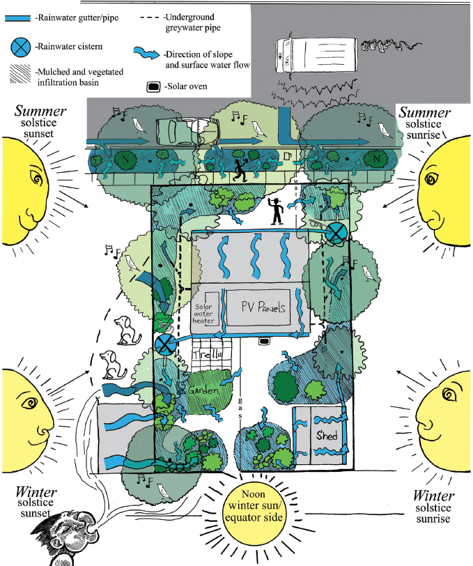
Fig. 4.27. An integrated rainwater- and greywater-harvesting landscape plan. Rain- and greywater-irrigated food-producing shade trees placed in a cooling solar arc around the home. Winter solar access retained for heating, cooking, power, and light. Impermeable hardscape reduced by removing driveway, planting a garden, and parking car on street. Garden placed in a sheltered sun & shade trap and irrigated by a cistern forming part of the trap. A wind- and noise-break of hardy, low-water-use, song-bird-attracting vegetation placed within basins on the perimeter to diffuse and cool the wind. The vegetation and a cistern also screen out the barking dog’s view so they stop barking. Pathways are raised to direct runoff to adjoining vegetation in basins. Greywater pipes and underground utilities are buried in raised pathways to prevent conflicts with vegetation. Greywater outlets into sunken basins. Roofs are guttered and sections of the land are regraded or bermed to utilize runoff flowing from off-site, and to retain all on-site rainwater on site. Street- and sidewalk-runoff irrigated shade trees buffer the home from the street. All of this invites friends to walk over and visit. Compare to pre-plan figures 2.4 and 4.4.
To make an integrated design:
1. Make multiple copies of your site plan (drawn to scale) to use as base maps for draft observations and ideas.
2. Play with different conceptual water-harvesting plan layouts. I recommend two options:
• Make cut-outs (in the same scale as your site plan) of the trees, cisterns, patios, gardens, and other elements you want to add to your site. Move these cut-outs around your site plan imagining how they will interact with the flows of your on-site resources (rainwater, greywater, sun, wind, etc.).
• Put tracing paper over your site plan and sketch where you could place various elements (trees, cisterns, patios, gardens, and other elements) you want to introduce to your site, and then see how they interact with on-site resource flows.
As you keep playing with various arrangements, ask yourself, “Where do I need water, where do I have it, how much do I have, and how/where can I best utilize it?” Remember, your goal is to increase site efficiency and maximize site potential. Refer to earlier sections of this chapter for conceptual ideas. See the resource appendix at HarvestingRainwater.com for more on integrated design patterns.
3. Refine your design by planning the water-harvesting details. After figuring out where you want to harvest water, it’s time to figure out how to do so. Re-read chapter 3 to determine what specific water-harvesting strategies are most appropriate for your needs, whether to harvest water in soil, tanks, or both. (Volume 2 provides a more thorough overview of water-harvesting earthwork strategies and their appropriate use, detailed implementation, and additional information incorporating greywater harvesting and use.)
Now, walk your land again, imagining how various strategies could work within the unique context of your site. Play more with ideas and layouts on paper—it’s much easier to make changes with a pencil and eraser than with a shovel. When you feel you’ve got your plan set, scratch out, stake, or otherwise mark locations of paths, trees, water-harvesting strategies, and other elements in the dirt at your site. Walk around your site, feeling what it would be like to inhabit this system. Are their adjustments that could make it more generative or even regenerative? Could you integrate any more sun and shade harvesting? Make any needed changes and if all feels good—go for it!