3Designing Software Architectures
In the previous chapter we presented the fundamentals of software architectures, and explained that the software architecture defines a design approach for the implementation of the functional and non-functional requirements defined by requirements engineering in a fully designed software system. Finding the right design approach or, in other words, the design of the software architecture, is what this chapter is all about.
As with the creation of a new algorithm for a complex, not completely formulated problem, architecture design is a creative process. The creation of a software architecture is much more than the work of an individual architect working alone, meditating until divine inspiration provides him with the right solution. This approach is doomed to failure, particularly in the case of complex software systems. You cannot expect an uncoordinated design to be accepted and implemented without contradictions by all the parties involved in the project. It is equally unrealistic to expect that a single person can keep track of all requirements and the consequences of his decisions. Communication between all involved parties is a significant success factor that must be taken into account during the design process.
In the first section, we provide an overview of the architecture design process. This is followed by proven design principles and heuristics, such as top-down and bottom-up, “divide and conquer”, and the simple-as-possible principle. In the sections that follow, we present a series of architecture-oriented development approaches that create links with existing and widely used methods and processes. We then address a series of techniques which, when appropriately applied, sustainably increase the quality of the design. Finally, we cover architectural and design patterns that offer a wealth of great ideas and solution building blocks for every architect.
3.1Integration with the iSAQB curriculum
An extract from the Designing software architectures section of the iSAQB curriculum [isaqb-curriculum] is provided below.
3.1.1Learning goals
 LG2-1:Select and adhere to approaches and heuristics for architecture development
 LG2-2:Design architectures
 LG2-3:Identify and consider factors influencing software architecture
 LG2-4:Decide on and design cross-cutting concepts
 LG2-5:Describe, explain and appropriately use important architectural patterns and architectural styles
 LG2-6:Explain and use design principles
 LG2-7:Plan dependencies between building blocks
 LG2-8:Design architecture building blocks/structural elements
 LG2-9:Design and define interfaces
3.2Overview of the architecture design process
As already explained in Chapter 2, the architect moves in at least two dimensions during the design process (see fig. 3-1): on the one hand with top-down and bottom-up changes to the levels of abstraction and, on the other hand, in a continuous iterative and incremental interplay between the individual architecture design activities.
We differentiate between the following four levels of abstraction (see also Chapter 2):
- Requirements and constraints
- Software architecture levels of abstraction:
- architecture style and technical infrastructure
- functional and technical architecture levels
- Program design and implementation
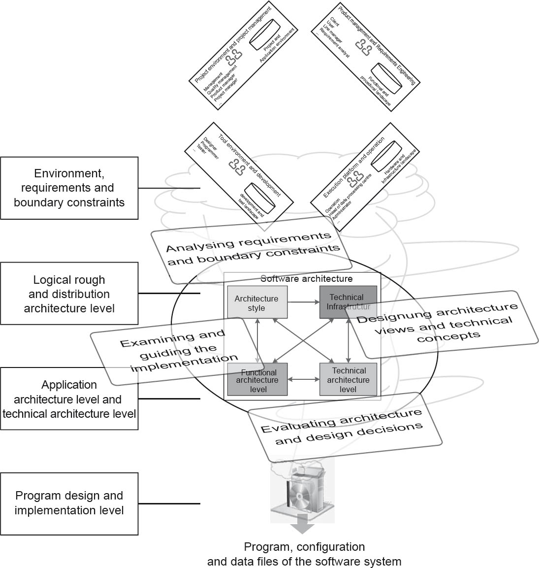
Figure 3-1Overview of the software architecture design process – iterative and incremental, top-down and bottom-up
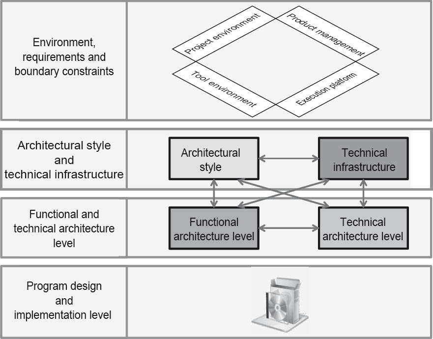
Figure 3-2The four levels of abstraction
It should be noted here that a different number and structure of levels of abstraction is possible. In particular, other approaches such as model-driven architecture (MDA) contain more extensively differentiated levels of abstraction (see also Chapter 2 and Section 4.3). However, the levels of abstraction proposed here provide a general top-level structure and usually permit projection onto these types of approaches.
As shown in figure 3-2, changes between these levels of abstraction are made on both a top-down and bottom-up basis. During the design process the architect moves from the requirements and constraints abstraction level via the levels of abstraction in the software architecture down to the lowest abstraction level, which consists of the software program itself, the program design, and implementation.
The topmost abstraction level (requirements and constraints) is the input for the architecture design. The functional and non-functional requirements or architecture standards to be followed can be found at this abstraction level. The software architecture itself can be found on the two levels of abstraction below this.
At the architecture style and technical infrastructure level, a three-layer architecture with rich internet deployment is defined. At the application architecture and technical architecture level the design of the specific functional and technical components and their interaction takes place.
The final abstraction level (program design and implementation) is located at the implementation level. It thus represents the final goal of the software architecture designed above it—in other words, a developed software system. The software architecture also defines the corresponding architecture requirements and rules to be followed by the programmers.
The creative and inventive nature of architecture design means that the design process itself has to be iterative and incremental: iterative to incorporate feedback and new information, and incremental to continuously move development forward. This is why the individual activities involved cannot be meaningfully arranged in a linear sequence. They are all areas with equal weighting that the software architecture has to devote sufficient energy to depending on the specific project situation. There is no defined sequence for the four activities of the design process shown in figure 3-3:
- Analysis of the requirements and constraints
- Development of architecture views and technical concepts
- Evaluation of architecture and design decisions
- Support and review of the implementation
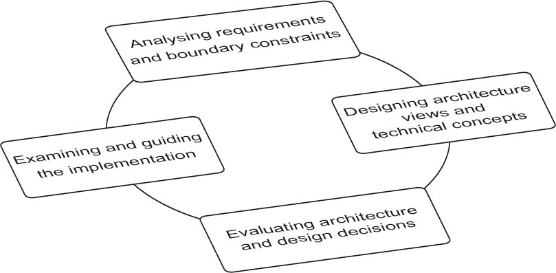
Figure 3-3The four major activities involved in the design process
During the architecture design process the software architect carries out these four activities virtually simultaneously, but in a sequence appropriate for the context of the project and its needs. However, the sequence should adhere to the following fundamental principle:
During the first activity (analysis of requirements and constraints), the available input is normally analyzed from the next higher abstraction level, with the aim of creating central decision criteria for the design to be developed—for example, the criteria for the decomposition of the system into individual building blocks.
In the next activity (development of architecture views and technical concepts), the actual design work takes place. The design process essentially involves making decisions. Building blocks have to be identified for the solution, overall solutions then have to be developed for the addressed abstraction level, and the best possible solution has to be selected based on the decision criteria established during the initial analysis.
Next, the architecture and design decisions are evaluated. This is where previously defined requirements scenarios can be played out to test the architecture.
The final activity covers the support and review of the architecture implementation at the next lower abstraction level. An architect can of course actively support the implementation and is permitted to program too, if required.
The architecture design process is thus a continuous top-down and bottom-up flow within the levels of abstraction, associated with a continuous change of activities performed interactively and incrementally. The architect steadily and continuously moves in two dimensions (abstraction level and area of activity) during the design process. The moves within these dimensions are not chaotic, erratic steps, but rather deliberate actions on the part of the architect.
During this process the software architecture, the system, and overall organization influence and stimulate each other continuously. The iterative/incremental and top-down/bottom-up procedures assist in coping with uncertainties associated with the design, making it simpler to detect design issues at an early stage. It is therefore important to take central views, levels of abstraction, functionalities, and non-functional requirements into account as early as possible.
Due to the changes of abstraction level, the architect also comes into contact with different stakeholders. If he is in the requirements and constraints area, he will increasingly talk to the customer and the requirements engineer. At the program design and implementation level, the appropriate dialog partners are programmers and testers. One of the architect’s tasks is thus to make full use of the central communication interface during the design process.
An architect who is currently in the “develop architecture views and technical concepts” activity area at the “architecture style and technical infrastructure” abstraction level may notice that two different deployment architectures are qualitatively equivalent, based on the previously derived decision criteria. Both a rich internet application and a fat client solution would equally well fulfill all the previously determined decision criteria.
The architect would then switch levels. At the “requirements and constraints” level, he would talk to the requirements analyst, explain the two alternatives to him and emphasize that requirements may be missing, thus determining which solution would be more favorable. The requirements analyst could discuss this with the stakeholders with the architect present. As a consequence, additional requirements could possibly be added to the requirements catalogue at this level.
The architect would then move back to the “analysis of requirements and constraints” activity area at the “architecture style and technical infrastructure” abstraction level, and would supplement the already created criteria catalogue with the aspects that result from the additional requirement(s). He would then take the extended criteria catalogue back to the “development of architecture views and technical concepts” activity area at the “architecture style and technical infrastructure” abstraction level, where he can now choose the better alternative based on the additional decision criterion.
Of course, this procedure doesn’t take place as mechanically as presented here. It nonetheless reflects a typical, realistic sequence in the architecture design process. This sequence is accompanied by phone calls, discussions, and workshops. Even though it’s not always transparent for the involved parties, the architect must always be aware of the level on which he is currently moving in two dimensions. This is the only way to ensure achievement of the right objectives, appropriate levels of communication, and an effective solution.
At the beginning of the design process, the first priority is to collect as much information as possible:
- Development of the domain knowledge and technical background knowledge necessary for the project
- Determination of existing systems in the organization and investigation of the extent to which they can be reused
- Determination of systems offered by third parties that perform a similar task to that of the system (or parts of the system) to be developed
- Reading appropriate technical literature in a search for the required solution approaches and procedural patterns
These are just a few examples of appropriate sources of information.
Based on this initial analysis, the central system concept can then be defined. What is the central task? To this end, the main task and responsibility of the system should be described in a few sentences, with reference to the most important terms and aspects of the functional domain. In most cases, this already provides an initial framework for the architecture, since this information enables us to assign the system to one of the three major system categories: information system, mobile system, or embedded system (see figure 2–3).
Depending on the system category, the next design steps and questions are immediately clear. If the system to be designed is an information system, a layered architecture would or might be used. Clarification is necessary on whether an interactive system or a batch system is desired. Which business processes need to be supported? Are transactions necessary using current organization data? What availability and performance is required?
However, if we are talking about an embedded system, the questions to ask are: Should it run on or control specialized hardware? Are there defined time guarantee requirements for time-critical operations? Is result-based control necessary? Is there a need for parallel control?
These and other questions help the architect to prepare the following steps. He must not, however, lose sight of the influencing factors and constraints, such as organizational and political aspects, technical and operational conditions/constraints, and the functional and non-functional requirements.
Organizational factors are things like the structure of the customer’s company, within the team, or of decision-making bodies. They can also be related to the available resources—for example, personnel, budget, or schedule requirements. Organizational standards such as process models and tools must also be taken into account. Legal aspects, too, need to be checked and taken into account where appropriate. Technical and operational factors such as existing software and hardware infrastructure, programming languages and styles, reference architectures, existing data structures, existing libraries, and existing frameworks must not be neglected.
The architect must continuously address these and other influencing factors and constraints. In this respect, the topmost abstraction level (requirements and constraints) provides the corresponding reference points from the four areas:
- Project environment and project management
- Product management and requirements engineering
- Implementation environment and operations
- Tool environment and development
These interface areas are the sources of the requirements and constraints but also interact with the architecture. If the architect can convincingly argue that a change of requirements or constraints from these interface areas can simplify the architecture, the decision-makers will seriously consider taking appropriate action. The consequences for other architectures, systems, and organizations must then naturally be taken into account. This is how the functional and non-functional requirements are created for the architectural design, distilled by the requirements engineering department of the organization responsible for the requirements. The architecture design reflects the feasibility of the requirements and their consequences for requirements engineering. If we find that changes to a small number of requirements would significantly simplify the architecture, it is the task of the architect to discuss these options with the relevant interface roles and decisionmakers.
3.3Design principles and heuristics
Heuristics are methods and procedures used to solve problems with efficient use of resources.
Depending on the starting point and the problem to be solved, various methods and procedures addressed in this chapter can help—for example, top-down and bottom-up, “divide and conquer” or the separation of concerns.
In contrast to reference architectures that clearly demonstrate how a specific software architecture should be structured, architecture principles [VA++09] represent proven fundamental principles that nevertheless provide no information on how they are to be used in specific situations.
With most of the principles addressed here, two main issues play an important role. These are: reducing the complexity and increasing the flexibility (and adaptability) of the architecture.
3.3.1Top-down and bottom-up
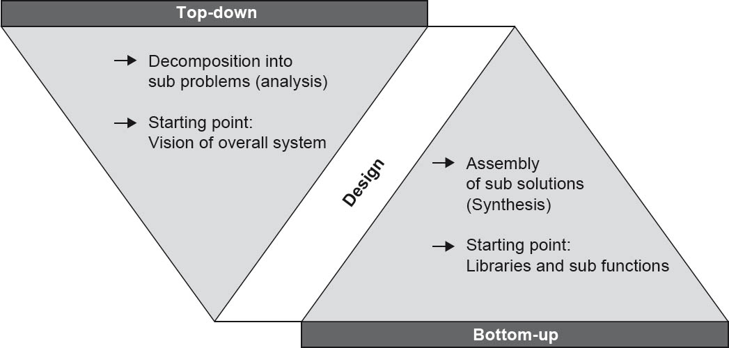
Figure 3-4Top-down and bottom-up
The top-down approach starts with the problem, and successively breaks it down into smaller sub-problems, finally ending up with mini-problems that can no longer be broken down and that can be directly solved.
The advantages of this approach are that all components are known, and the risk of creating unsuitable results is extremely low. These advantages, however, are only visible at a late stage, and misunderstandings manifest themselves in the result at the end of the project.
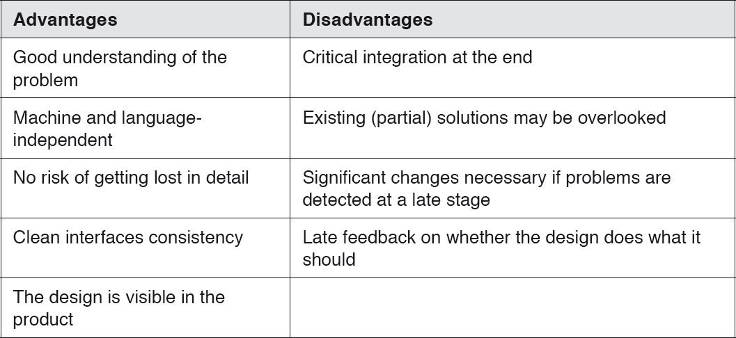
Table 3-1Top-down
In contrast, the bottom-up approach starts with the specific machine and builds additional “abstract machines” on top of it. The developers start with the implementation without full knowledge of all system details. The partial solutions are combined with each other until finally a complete “problem solution machine” is created.
In contrast to the top-down method, results are achieved quickly, and risks are identified at an early stage. On the other hand, partial results can potentially be unsuitable for subsequent steps.

Table 3-2Bottom-up
The two approaches are not mutually exclusive and can complement each other.
3.3.2Hierarchical (de)composition
3.3.2.1Divide and conquer
The “divide and conquer” principle is used in many branches of IT and describes a reductionist approach that breaks a task down into ever smaller partial tasks until the complexity of these tasks reaches a manageable level. This principle is also used in numerous algorithms, and makes use of the fact that the effort required to solve problems is reduced when they are broken down into smaller sub-problems.
Similarities to the top-down design approach are clearly recognizable. A system or a component is broken down into ever smaller, relatively independent components, resulting in a hierarchical (or tree-type) component structure.
This approach can be used to encapsulate single or multiple functions or responsibilities, or to separate different aspects of a problem from one another.
Depending on the algorithm, various approaches are possible for solving the overall problem, for example:
- The solution for the final sub-problem is also the solution for the overall problem. When searching in a binary tree, the final step of a search corresponds to the appropriate position in the tree.
- Partial solutions are combined to form an overall solution.
- The solution for the overall problem is selected in accordance with specific criteria from the best partial solution. With some optimization problems, the solution space is subdivided, and the optimal solution is sought among the partial solutions. From these optimal partial solutions, the best solution is then selected as the overall solution.
3.3.2.2Decomposition principles
Decomposition is an important approach for reducing complexity [Sta11]. One of the central principles of decomposition is encapsulation, without which undesired dependencies between individual parts of the system can result. Encapsulate complexity in components and treat these as black boxes. Components should make no assumptions regarding the internal structure of other components.
Other important aspects are low coupling and high cohesion, but we will go into more detail on these later.
Instead of reinventing the wheel, you should reuse already established and proven structures.
Design iteratively, and determine and evaluate strengths and weaknesses based on a prototype design.
Break down the system into elements that are as independent as possible, and separate responsibilities clearly and understandably.
3.3.2.3The “as-simple-as-possible” principle
As Albert Einstein once said, “Make things as simple as possible, but no simpler.”
Simplicity has desirable effects. It makes things easier to understand and prevents problems becoming hidden by excessive complexity. Simple structures are easier to understand and are therefore easier to change. Any dependencies can also be more easily determined and more easily removed.
This principle is closely related to the term “suitability”, as a degree of complexity can be appropriate in a specific situation. Appropriate use of complexity, however, is a matter of experience. In case of doubt, preference should be given to the less complex option.
3.3.2.4Separation of concerns
The principle of separation of concerns states that different aspects of a problem should be separated from one another, and that each sub-problem should be addressed on its own. As with many other principles, it is based on the principle of “divide and conquer”.
Concerns and responsibilities should be addressed at all levels of the design, from individual classes through to complete systems.
The separation of functional and technical elements is particularly important and should be a fundamental objective. Doing so ensures that the functional abstraction is separated from the specific technical implementation, and allows both aspects to be further developed independently of one another (or makes it easier to replace and reuse individual program elements). An additional advantage is increased quality due to improved traceability of changes and their impacts.
The modularity of a system determines the extent to which it is broken down and encapsulated in self-contained building blocks (modules). The principle of separation of concerns can be used in conjunction with the principle of information hiding to implement the modularity principle. The modularity principle states that one should aim to use self-contained system building blocks (modules) with simple and stable relationships. The building blocks of a modular system should be black boxes and hide their internal workings from the outside world.
3.3.3Lean interfaces and information hiding
3.3.3.1Information hiding
The principle of information hiding was developed by David Parnas in the early 1970s.
As already explained, the complexity of a system should be encapsulated in building blocks. This increases flexibility when it comes to making changes. The building blocks are regarded as black boxes; access to their internal structure is denied and instead takes place via defined interfaces. Only the subset of the total information that is absolutely necessary for the task should be disclosed.
3.3.3.2Use of interfaces
The most important aspects of an architecture are interfaces and the relationships between building blocks. Interfaces form part of the basis of the overall system, and enable the relationships between the individual elements in the system. The individual building blocks and subsystems communicate and cooperate with each other via interfaces. Communication with the outside world also takes place via interfaces.
3.3.4Regular refactoring and redesign
Putting the key into the lock and opening the door of a new house for the very first time is a wonderful experience. The individual rooms still smell of the final work carried out by the painters, carpenters, and others. Everything is clean, and the kitchen is tidy. A few weeks later the fresh smell has gone. And if you don’t tidy up, maintain, repair, and throw things out on a regular basis, a new house can very quickly become an unattractive place.
The same principle applies to software and its architecture. Software is normally continuously enhanced. If you don’t tidy up regularly and remove rough edges during the process, additional features created as a result of time pressure and bug fixing will not be integrated properly into the underlying architecture, and even the best software architecture will degenerate in a very short time. The costs for further development and renovation of software are often so high that the effort is no longer economically viable. Starting again from scratch then becomes an option that can’t be excluded.
It is therefore necessary to “refactor” the software at regular intervals and to carry out a redesign. When defining “refactoring”, Martin Fowler differentiates between the noun “refactoring” and the activity of “refactoring”:
- Refactoring (noun) [Fow99]:
“A change made to the internal structure of software to make it easier to understand and cheaper to modify without changing its observable behavior.”
- Refactoring (verb) [Fow99]:
“To restructure software by applying a series of refactorings without changing its observable behavior.”
Refactoring serves to adapt dependencies so that incremental development is made simpler.
Take the example of a bugfix in a class that accesses another class via multiple dereferences in the format u.getV(). getW().getX().getY().getZ(). doSomething(). Such dereferencing chains should be avoided, since they create direct dependencies across entire networks of classes. In this case, a possible refactoring approach would be to place a new method getZ() in Class U.
It is critical that time is regularly spent on refactoring and redesign, and appropriate resources must be planned for in the overall project calculation.
3.4Architecture-centric development approaches
In this section we present some contemporary architecture-centric development approaches and concepts used in the design and implementation of architectures. The goal is to provide a brief overview of development approaches that are architecture-centric. The list is by no means complete.
3.4.1Domain-driven design
Domain-driven design (DDD) is a collection of principles and patterns that assist developers in the design of object systems. The term was coined by Eric Evans and, since it makes it easier to structure large systems by functional domains, is an important factor for developing a better understanding of microservices. Using this approach, each subsystem forms a separate unit.
3.4.1.1Functional models as the basis for a design
You should begin your design by structuring the functional domain [Sta11]. The domain model should be structured on a purely functional basis and needs to be accepted throughout the project. This model improves communication between domain experts and developers, and enables precise formulation of requirements. The domain model can be tested extremely easily using direct mapping in the software. On the basis of this model, a common, domain-specific language is created whose elements should be included in the project glossary.
This universal language is the so-called ubiquitous language, and is a central concept of domain-driven design. This language should be used in all areas of software development—i.e., all project members should use the same terms as the domain experts in the source code as well as in databases and other components. It describes the functional domain, elements of the domain model, classes, methods, and so on.
Figure 3–5 shows the elements of a domain model created using domain-driven design.
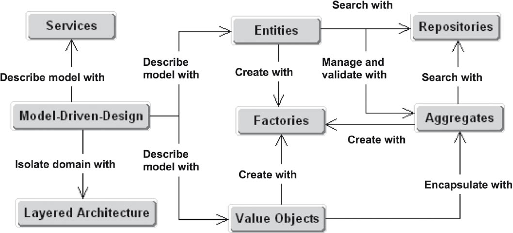
Figure 3-5Component elements of a domain model
3.4.1.2Systematic management of domain objects
The entities represent the core objects of a functional domain and are normally persistent. Within the domain they have a consistent identity and a clearly defined lifecycle. An entity is a “thing” in your system. It’s often useful to imagine entities in the form of nouns (i.e., people or places).
Value objects describe the state of other objects and do not have an identity of their own. They simply describe objects that have identities. They can consist of other value objects, but never entities. In contrast to entities, value objects cannot be modified.
Services are operations that represent the process sequence of the domain. They are not recognized by entities and don’t usually have a status of their own. The inputs and outputs of these operations are entities, aggregates, or value objects (i.e., domain objects).
For the management of domain objects, Evans recommends three different management objects:
- Aggregates
An aggregate encapsulates interlinked domain objects and has precisely one entity in the form of a root object that represents sole access to the aggregate. External objects may only contain references to the root entity.
- Factories
Factories encapsulate non-trivial, complex object structures. Factories have no access to other layers and serve exclusively for the construction of functional objects.
3.4.1.3Structuring of the functional domain
The structuring of the functional domain normally takes place on the basis of functional objects or user transactions.
- Decomposition based on functional objects is appropriate if
- Reuse is important.
- The functional logic is complex, extensive, or flexible.
- The object-oriented paradigm is well understood.
- This type of decomposition more or less corresponds to object-oriented decomposition.
- Structuring based on user transactions is appropriate in the case of
- Simple data acquisition and simple data operations
- Integration of external systems
- Simple or limited functional logic
- Limited experience with object-oriented procedures
A user transaction corresponds to an action that a system user can execute, including all system-internal operations such as checking input data.
The most important thing here is preservation of design integrity. Where possible, you should break down all parts of the system based on similar aspects and apply (and document) this concept consistently.
3.4.1.4Types of domains
DDD subdivides a system into the following domains:
- Core domain
- Generic subdomain
- Supporting subdomain
The core domain contains the core functionality of the system and describes the reason for the existence of the system. Where possible, it should only be implemented by the most experienced developers.
The generic subdomain contains functionality of importance to the business but which does not form part of the core domain—for example, the generation of invoices or sending of letters. It can be bought in or outsourced.
The supporting subdomain contains supporting and subordinate functionality, and can also be handled by less experienced developers. It should, however, be strictly separated from the core domain—for example, using an anti-corruption layer.
3.4.1.5Integration of domains
As already mentioned, each subsystem should form a separate unit. A further important term in DDD is “bounded context”, which makes it easier to determine the appropriate granularity for microservices. Each model has a context, and a complex functional domain very probably consists of several bounded contexts.
Various possibilities exist for the integration of different domains. These include:
- Published Language
There should be a common language via which the domains can interact—for example JSON or XML.
- Open Host Service
This is a classic SOA form of interaction. One domain specifies a protocol via which other domains can use it—for example, the RESTful web service.
- Anti-Corruption Layer
Uses services from another domain via an isolation layer.
- Separate Ways
Two domains are completely separate from one another and have no integration.
3.4.2MDA
Model-driven architecture (MDA) is a concept that enables the generation of (parts of) applications from models, such as UML. MDA was developed by the Object Management Group (OMG).
Model-driven software development (MDSD) generates software components automatically via transformations from models [RH06]. MDSD uses models and generators to improve software development.
The model forms the core of MDA, and is typically formulated with the aid of a domain-specific language (DSL). The DSL can either be text-based or graphical. However, a DSL is not mandatory. MDA, MDSD and other, similar approaches are DSL-independent.
There are two ways to create an executable application. Executable models are either interpreted directly by a virtual machine (such as the Object Management Group’s Executable UML), or converted into an executable application by means of one or more transformations.
Model-driven architecture (MDA) as defined by the OMG is nothing more than a special instance of the MDSD approach, and has nothing to do with architecture. While model-driven software development offers a choice of modeling languages and no restrictions on transformation into executable applications, MDA has more specific requirements in this respect. For example, the DSL to be used should be MDA-compliant (i.e., defined using the OMG’s Meta-Object Facility, or MOF, which forms the metamodel). In practice, mainly UML profiles are used.
The platform-independent aspects are modeled within the scope of a platform-independent model (PIM). The PIM is subsequently mapped to one or more platform-specific models (PSMs). The PSM thus creates the link to a specific platform, from which the code can then be generated.
The MDSD approach essentially has the following advantages:
- Increased development efficiency
- Specialist experts can be better integrated
- The software can be modified more easily
- Improved implementation of the software architecture
- The functional logic can be relatively easily ported to other platforms
Model-driven software development, however, requires establishment of an infrastructure consisting of DSLs, modeling tools, generators, platforms, and so on, as well as plenty of discipline when creating models. The specification effort is also greater, and usually only a part of the model can be automatically transformed into artifacts.
3.4.3Reference architectures
3.4.3.1Generative creation of system building blocks
If specific actions have to be carried out recurrently in the same or a similar way, they can be automated with the aid of generative techniques [VA++09]. Software systems often have to be created that differ only in a few details from other systems, with common features that are functional or technical. One overarching goal in software development is the greatest possible reuse of system building blocks.
Template-based generators are a popular means of software generation. A template in this context is mainly text-based. Part of the template accesses the input data, which are also largely text-based. Situations in which a template can be applied are defined with the help of patterns. Using predefined rules, the template is modified and the output is based on the generator input. Established examples of this approach are Java Emitter Templates (JET) or the XSLT transformation language, which forms part of the Extensible Stylesheet Language XSL and serves to transform XML documents.
Another generation technique uses API-based generators that are used (among other things) for generating PDF documents. In this case, the entire structure of the document to be generated is described via an API (Application Programming Interface).
Model-driven software development (MDSD) is a good example of the use of generators in software development.
3.4.3.2Aspect orientation
A program can contain tasks that occur in several separate locations within the code. If activities have to be logged, specific code must be included before and after the activity. If the logging is designed to appear in several places in the program, the developer writes or copies the same code in different places. Other examples include the repetition of database access, transaction management, and authentication. Such multiple occurrences of code are inconsistent with the “don’t repeat yourself” (DRY) concept. Aspect orientation enables encapsulation of such tasks so that the task is programmed just once but can be executed in several places.
Aspect orientation implements the principle of separation of concerns for “cross-cutting concerns”. Cross-cutting concerns—also referred to as system-level concerns—affect the entire system or technical constraints, and cannot be easily encapsulated. They are not actually necessary to a specific functionality (such as logging).
Examples of cross-cutting concerns are:
- Logging
- Performance profiling
- Validation
- Session
- Synchronization
- Security
- Error handling
- Event-driven programming (for example, PropertyChangeEvents)
- Software tests
Established implementations of aspect-oriented programming are AspectJ, JBoss AOP, and AspectWerkz.
3.4.3.3Object orientation
In the context of object orientation, procedures are called operations or methods. The idea behind object orientation is the mapping of real-world concepts in objects—for example, a car. This object can also store its data (type, color, and so on) and provides the operations necessary for editing and querying this data.
An important feature of object orientation is classification. Let’s stick with the example of the car. A car dealer doesn’t just have a single car, but rather many different cars. The class Car can thus be regarded as an abstraction. Object-oriented code defines such a class once but allows it to be instanced several times.
If an entire range of objects can be instanced from a class, you need to differentiate between them at runtime. For this reason, each object has its own unique object ID that can be used to call up the object’s operations.
Figure 3–6 shows a UML class diagram for the class Car and an object diagram with two instanced objects of this class.
To specify possible interactions between objects more precisely, there is a range of relationships available such as association, aggregation, inheritance, interfaces, and abstract classes.
With these additional abstractions, object-oriented architectures provide better modularization support than procedural architectures. Generally, it is easier to implement the principles described above, but that doesn’t automatically make an object-oriented architecture a good architecture. Here too, the architect has to develop an appropriate object-oriented model and correctly apply the associated techniques and approaches.
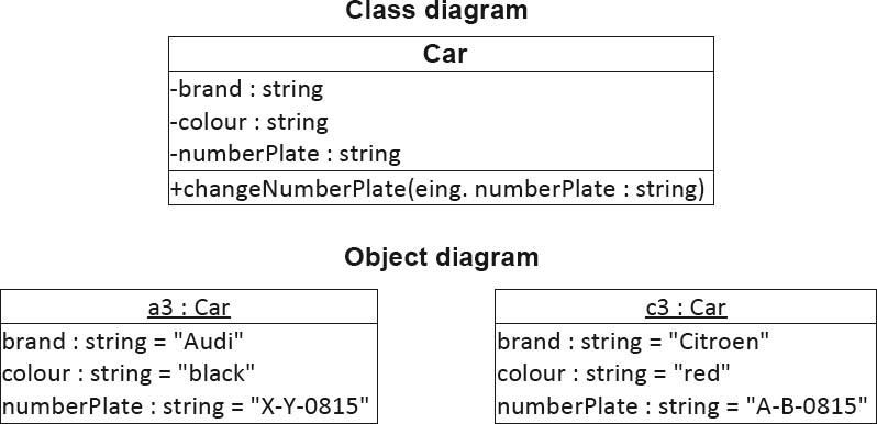
Figure 3-6Example of a class diagram and its associated object diagram
3.4.3.4Procedural approaches
A classic (and still popular) approach for the structuring of architectures is the use of procedures. Procedures enable a complex algorithm to be broken down into reusable sub-algorithms that form the basis for implementation of the principle of separation of concerns.
Many programming languages such as C or Cobol are based on procedures, and object-oriented systems (such as Java static methods) also support procedural abstractions.
3.5Techniques for a good design
In addition to the architecture principles already presented, there are specific techniques for achieving a good design that a software architect should know. An important challenge in the design of software architectures is effective management of the interdependencies of the individual software building blocks. Sometimes dependencies cannot be avoided, and sometimes they are even advantageous—for example, if a message has to be sent to another class, or a specific method from a different subsystem has to be called.
What’s important is that you always discuss designs and keep your alternatives and options open. Models are not reality, and should always be coordinated with the end-user and the client.
3.5.1Degenerated design
With software that is frequently modified over long periods, the structure of the software can degenerate in the course of time. This is a general problem. In the beginning, architects and designers create a clean, flexible software structure that can still be seen in the first version of the software. However, after the initial implementation, changes in requirements are usually unavoidable. This means that the software has to be modified, extended, and maintained. If the initial design is not taken into account during this process, the original structure can become unrecognizable and can only be understood with difficulty.
There are three basic symptoms that indicate a degenerated design:
- Fragility
Changes in one place can result in unforeseen errors in other places.
- Rigidity
Even simple modifications are difficult and affect a large number of dependent components.
- Low reusability
Components cannot be individually reused due to their many dependencies.
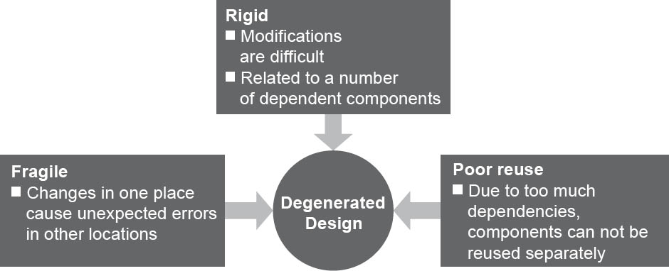
Figure 3-7Symptoms of a degenerated design
3.5.2Loose coupling
As already explained, the relationships between the building blocks and components enable effective collaboration, and thus form part of the basis of the entire system. Relationships, however, lead to dependencies between components, which in turn can lead to problems. For example, a change to an interface means that all building blocks that use this interface may have to be changed too.
This relationship between building blocks, along with its strength and the resulting dependency, is referred to as coupling.
A simple of measure how strongly a component is coupled to other components is to count the relationships between them. In addition to quantifying it, the nature of a coupling is important too. Some examples of types of coupling are:
- Call
A coupling exists when a class directly uses another class by calling a method of that class.
- Generation
A different type of coupling exists when a building block generates another building block.
- Data
A looser coupling exists when classes communicate via a global data structure or solely via method parameters.
- Execution location
A hardware-based coupling exists when building blocks have to run in the same runtime environment or on the same virtual machine.
- Time
A temporal coupling exists when the chronological sequence of making calls to building blocks impacts the end result.
- Inheritance
In object-oriented code, a subclass is already coupled to its parent class due to the inheritance of attributes. The level of coupling depends on the number of inherited attributes.
The aim of loose coupling is to reduce the complexity of structures. The looser the coupling between multiple building blocks, the easier it is to understand an individual building block without having to inspect a lot of other building blocks. A further aspect is the ease of modification. The looser the coupling, the easier it is to make local changes to individual building blocks without impacting other building blocks.
An example for loose coupling is the observer pattern.
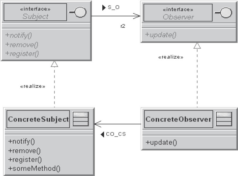
Figure 3-8A sample observer pattern
The only thing that the subject knows about its observers is that they implement the observer interface. There is no fixed link between observers and a subject, and observers can be registered or removed at any time. Changes to the subject or the observer have no effect on the other party, and both can be reused independently of one another.
3.5.3High cohesion
The term “cohesion” comes from the Latin word cohaerere, which means “to be related”.
The principle of loose coupling often leads to the principle of high cohesion, as loose couplings often lead to more cohesively designed building blocks.
A cohesive class solves a single problem and has a specific number of highly cohesive functions. The greater the cohesion, the more cohesive the responsibility of a class in the application.
Here too, it’s a matter of how easily system building blocks can be locally modified and understood. If a system building block combines all the properties necessary for understanding and changing it, you can alter it more easily without involving other system building blocks.
You should not group all classes of the same type in packages (such as all filters or all entities), but instead group by systems and subsystems. Cohesive packages accommodate classes of a cohesive functional complex.
3.5.4The open/closed principle
The open/closed principle was defined in 1988 by Bertrand Meyer and states that software modules should be open for extension but closed for modification.
“Closed” in this context means the module can be used without risk since its interface no longer changes. “Open” means the module can be extended without problems.
In short:
A module should be open for extensions
The original functionality of the module can be adapted by means of extension modules, whereby the extension modules handle only the deviations between the desired and the original functionality.
A module should be closed for modifications
To extend the module, no changes to the original module are necessary. It should therefore provide defined extension points to which extension modules can be connected.
The solution of this apparent contradiction lies in abstraction. With the aid of abstract basic classes, software modules can be created that have a defined, unchangeable implementation, but whose behavior can be freely altered via polymorphism and inheritance.
Here’s an example of how not to do this:
void draw(Form f) {
if (f.type == circle) drawCircle(f);
else if (f.type == square) drawSquare(f);
...
This example is not open for extensions. If you want to draw additional shapes, the source code of drawing method would have to be modified. A better approach would be to move the drawing of the shape into the actual shape class.
3.5.5Dependency inversion
The principle of dependency inversion states that you should not permit any direct dependencies, but instead only dependencies of abstractions. This ultimately makes it easier to replace building blocks. You should decouple direct dependencies between classes using methods such as the factory method. One of the core reasons (not the only, obviously) for using a dependency inversion is an architectural style with which it makes it very easy to write mocked unit tests, thus making a TDD approach more viable.
Let’s look at an example. Assume that you want to develop a Windows application that reads the weather forecast from the Internet and displays its graphically. On the basis of the principles described above, you relocate the functionality that takes care of the handling of the Windows API into a separate library.

Figure 3-9A sample Windows application
The module for displaying the weather data is now dependent on the Windows API, but the API is not dependent on the display of the weather data. The Windows API can also be used in other applications. However, you can only run your weather display application under Windows. In its current form it won’t run on a Mac or in a Linux environment.
This problem can be solved with the aid of an abstract operating system module. This module specifies which functionality the specific implementations have to provide. In this case, the operating system abstraction is not dependent on the specific implementation. You can add a further implementation (for example, for Solaris) without any problems.

Figure 3-10Dependency inversion
3.5.6Separation of interfaces
In the case of multiple use of an extensive interface, it can be useful to separate the interface into several more specific interfaces based on:
- Semantic context, or
- The area of responsibility
This type of separation reduces the number of dependent users and thus also the number of possible consequent changes. Furthermore, a number of smaller, more focused interfaces are easier to implement and maintain.
3.5.7Resolving cyclic dependencies
Cyclic dependencies make it more difficult to maintain and modify systems, and prevent separate reuse.

Figure 3-11Cyclic dependency
Unfortunately, cyclic dependencies can’t always be avoided. However, in the example shown above, you can do the following:
- Separate out the parts of A that are used by C in the form of abstraction CA.
- The cyclic dependency is dissolved by means of an inheritance relationship from A to the abstraction CA.
3.5.8Liskov’s substitution principle
The Liskov substitution principle is named after Barbara Liskov, and was originally defined as follows:
Let q(x) be a provable property of objects x of type T. Then q(y) should be provable for objects y of type S, where S is a subtype of T.
This principle states that a basic class should always be capable of being replaced by its derived classes (subclasses). In such a case the subclass should behave in exactly the same way as its parent class.
If a class does not comply with this principle, it’s quite likely that it uses inheritance incorrectly in terms of generalization/specialization.
The capability of many programming languages to overwrite methods can be potentially problematic. If the method’s signature is changed—for example, by changing visibility from public to private—or a method suddenly no longer throws exceptions, unwanted behavior can result and the substitution principle is then violated.
An example for violation of this principle, which at first glance is not so obvious, is to model a square as a subclass of rectangle—in other words, the square inherits all the attributes and methods of the rectangle.
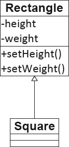
Figure 3-12A square as a subclass of a rectangle
First of all we notice that a square only requires a single attribute, namely the length of its sides. A square, however, can also be defined using two side lengths, which then requires you to check that the property of a square (i.e., all sides of equal length) is fulfilled. To do this, the methods setHeight and setWidth have to be modified so that they set the height and width of the square to the same value.
Initially, this doesn’t appear to be a problem. A crucial problem first arises in the use of a square in place of a rectangle, since a rectangle cannot always be replaced by a square. For example: A picture is to be given a rectangular frame. The client passes the height and width of the picture, the coordinates of its top left-hand corner, and a square (not a rectangle) to the drawFrame method. The drawFrame method now calls the setHeight and setWidth operations of the square, and the result is a square with the side length equal to the width of the picture. This is because the setWidth method sets the width and height of the square to the same value.
3.6Architectural patterns
Patterns are an important instrument in the design and development of software. Patterns exist in many areas of software development—for example, design patterns, architectural patterns, analysis patterns, software organization patterns, and pedagogic patterns.
The classification of architectural patterns takes place in accordance with Frank Buschmann’s system of four categories. The underlying concept is to use the problem addressed by the pattern as the basis for the classification.
3.6.1Adaptable systems
Patterns in this category support the extension of applications and their adaptation to evolving technologies and changing functional requirements.
3.6.1.1Dependency Injection
In object-oriented design, problems often occur due to the necessity of creating a concrete instance of an abstract interface.
- Who manages the lifecycle of the instances used?
- Who decides which specific class shall ultimately be instanced at runtime?
This pattern provides an independent building block for this purpose, namely: the assembler.
The assembler determines at runtime how to address the questions listed above. The assembler passes references to specific instances of the dependent objects. It can be regarded as a type of “universal factory”.
It first inspects ServiceUser for necessary dependencies (Service) and, via meta-information, generates or determines a ServiceImplementation that offers the required service. It then “injects” this service implementation into ServiceUser and thus decouples the classes from their dependencies.
Established Java implementations for dependency injection are:
- JEE 6: Contexts and Dependency Injection (JSR-299)
- The Spring Framework
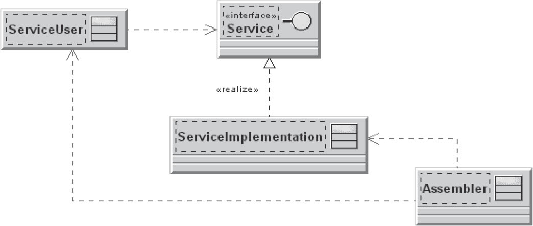
Figure 3-13Dependency injection
3.6.2Interactive systems
Interactive system patterns support the structuring of interactive software systems.
3.6.2.1Model-view-controller pattern
Porting of an application to a different platform should not result in restructuring of the entire application. Here, the aim is simple changes or extension and reuse of individual components.
User interfaces change frequently. The same information has to be provided in different ways in different windows, resulting in complexity in the required frameworks. Various groups of users require different layouts or formats. It is difficult to strike a balance between consistent views of a model and performance problems caused by excessive updates.
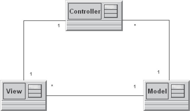
Figure 3-14Model-view-controller
To solve this problem, the user interface is divided into three areas of responsibility. The model encapsulates the normally stable business logic and its data. View components provide views of the model. The controller processes user events, executes the corresponding business logic, and triggers updates of the view components.
A good example of this approach is a spreadsheet program that provides a detailed tabular view and an easily digestible chart view of the same data model.
3.6.2.2Model-view-presenter pattern
Model-view-presenter (MVP) is an architectural pattern for interactive software systems with user interface-oriented applications. It is based on the model-view-controller pattern and focuses on strict separation of the user interface and business logic (separation of the view and the model). The principle behind this pattern is that applications are broken down into three components:
- The model contains the business logic and all of the data required by the view. It is controlled solely by the presenter and knows neither the view nor the presenter.
- The view represents the presentation layer and has an extremely simple design. It contains absolutely no control logic, and is solely responsible for the presentation and the receipt of user input.
- The presenter links the view to the model and controls the logical flow between the layers. It collects all application use cases, accepts user input from the view, calls methods in the model, and sets the data in the view.
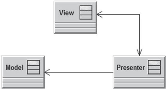
Figure 3-15Model-view-presenter
Due to the simple construction of the presentation layer, views can be replaced by other views. This way, systems can be modified so that they can be used on different platforms and, compared with MVC, are easy to test. Since its definition by Martin Fowler in 2004, MVP has been used for the development of rich clients.
In contrast to MVC, the view in MVP has absolutely no relationships with the model, since the interaction with the model is strictly controlled via the presenter. This results in a slightly different distribution of responsibilities among the three components. In an MVP situation, the model is provided to the presenter via an interface. In contrast, due the absence of an interface, the MVC model is more strongly coupled to the controller. Using the MVC approach, the view knows the model and enables data synchronization. With a passive MVP view, the presenter takes over data binding, and the view does not know the model. In addition, the MVC has no interface and is thus more difficult to replace.
3.6.2.3Presentation-abstraction-control
Increasing application functionality also increases the complexity of the user interfaces. With complex user interfaces, different areas of functionality can become intermingled, which reduces maintainability. In addition, simple decomposition (as found in the MVC pattern) results, among other things, in unsatisfactory response times when all user events are processed by a single controller.
In this pattern, the structure of the user interface is broken down into hierarchically cooperative “agents”. Basic functionality is used by intermediate levels that then provide functionalities for the individual, bottom-level elements of the user interface. Each agent consists of a controller, abstraction, and the view. The controller is the agent’s interface to the next higher- and lower-level agents in the hierarchy, and controls its area of responsibility. The abstraction adapts parts of a complete model into a local model that only includes the elements required for the local views. This strictly hierarchical separation enables parallelization of processing operations within the user interface, especially if only parts of the complete model are available.
The Eclipse IDE is a good example: The workbench offers a menu bar, a toolbar, a working area, and a status bar. Perspectives offer these for use as embedded operating elements limited to each perspective’s subject area. These include areas for margin views and editor windows, which are then filled by specific content editors and views with menu entries of their own.
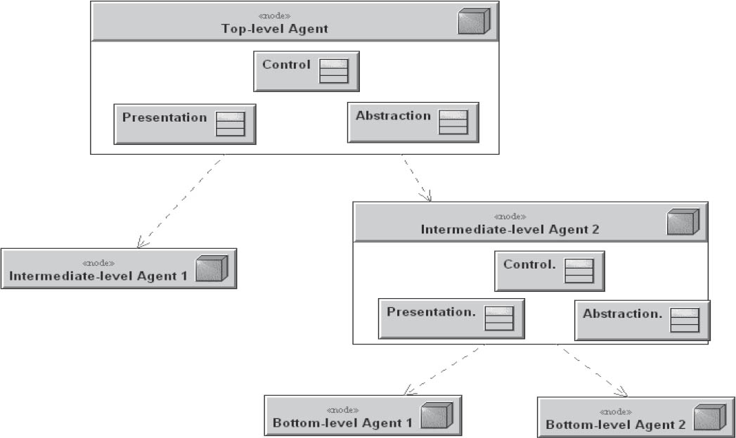
Figure 3-16Presentation-abstraction-control
3.6.3From chaos to structure
Patterns in this category serve to avoid a mess of components and objects. In particular, they provide support for decomposition of a high-level system task into cooperative subtasks.
3.6.3.1Layered architecture
This pattern assists in the structuring of large applications. The focus is on the development of a complex system whose dominant characteristic is a mixture of complex services that build on one another.
Dependent high- and low-level operations form functions that access each other, but that can be subdivided into layers with the same level of abstraction. To achieve reusability and/or portability, subdivision takes place into closed layers, so that the effects of subsequent changes only affect that layer.
The solution to the problem lies in stacking the system in horizontal layers that encapsulate operations on the same level of abstraction. The level of abstraction increases with the number of lower layers. Information exchange takes place via interfaces referred to as services. A higher layer uses service provided by the layer below it. Communication across multiple layers is not permitted. This separation results in specialization of the individual layers in specific process aspects such as data storage or user interaction.
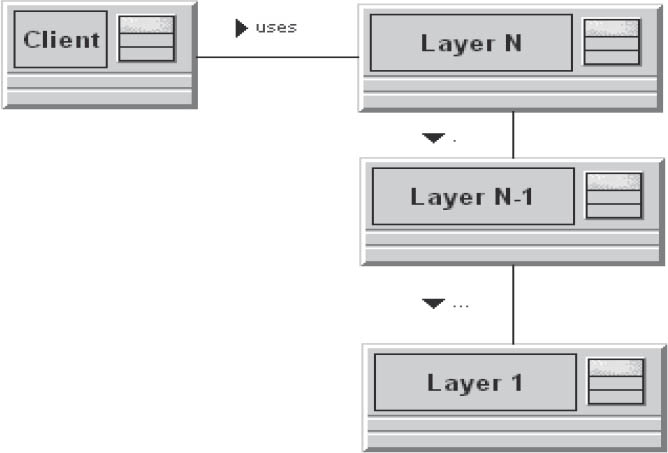
Figure 3-17Layered architecture
This simple concept reduces the number of possible dependencies between components and provides increased reusability. However, it can also result in increased overhead if a layer merely passes requests for provision of specific services to the next layer. Furthermore, changes such as adding a data field have a vertical effect on all layers.
Performance issues can be resolved by skipping over specific layers, although this once again creates additional dependencies.
3.6.3.2Pipes and filters
The pipes-and-filters architectural pattern is based on a sequence of processing units (filters) that are connected to each other via data channels (pipes). Each filter forwards its results directly to the next filter. The pipes transport the intermediate results from one filter to the next, which involves decoupling of various aspects of the process:

Figure 3-18Pipes and filters
The filters are not aware of each other, and can be combined in any sequence via the pipes, thus providing a high level of reusability for the individual pipes and filters. The downside is that that error states that occur during processing are difficult to deal with.
Typical examples of use for this architectural pattern are:
- Compilers with stepwise processing and forwarding of the result following each processing step. Typical phases are lexical analysis, parsers, and code generators.
- Digital signal processing with the following filters:
Image acquisition, color correction, image effects, and compression, which all forward digital image data to each other.
3.6.3.3Blackboard
Several specialized subsystems make their knowledge available for creation of a potentially incomplete or approximate solution.
Figure 3–19 shows a UML diagram of the blackboard pattern.
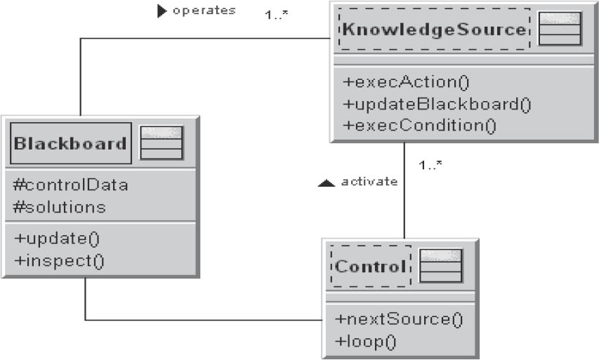
Figure 3-19Blackboard
The elements of a blackboard are:
- One or more independent KnowledgeSources that analyze the problem from a particular point of view and send solution proposals to the Blackboard
- A central Blackboard that manages the solution approaches or solution elements of the KnowledgeSources
- A control component that monitors the Blackboard and, where necessary, controls the execution of the KnowledgeSources
Examples for the use of the blackboard pattern are software systems for image processing, image recognition, voice recognition, and system monitoring.
3.6.4Distributed systems
Patterns in this category make statements on proven forms of task distribution and the methods with which subsystems communicate with each other.
3.6.4.1Broker
Current developments in the software industry have resulted in new application requirements. The software must be capable of running on a distributed system, but must remain unaffected by the continual structural modifications that take place in such systems.
The resources that the applications need to access can be distributed at will, so it has to be possible for the individual software components to access these distributed resources. Transparency is key in such situations. For an individual component, only the availability of a used service is relevant, and it doesn’t matter where the service is physically provided within the system. An additional factor is that systems are subject to continuous modification processes. This means that the components involved in a process may well change at runtime.
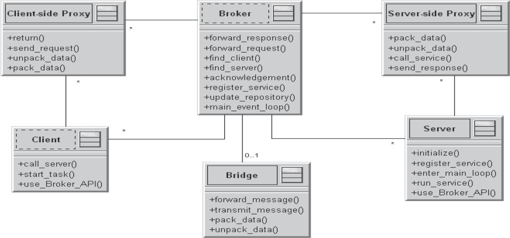
Figure 3-20Broker
The application must compensate for this with appropriate measures. It is essential to avoid situations in which the application user has to (or can) become involved with the details of the architecture.
In the architecture model of a distributed application, a “broker” component is introduced. This serves as a kind of switching center for communication between servers and clients. The broker component is the central point of communication. Each server independently registers itself with the broker. For each service to be provided by a server, a corresponding service interface is implemented on that server, and these interfaces are communicated to the broker. When clients wish to access a specific service, they send their requests to the broker. The broker then localizes the available server for the respective service and forwards the client’s request to it. Following processing of the request, the server then sends the response back to the broker, and the broker forwards the response to the correct client.
3.6.4.2Service orientation
Service-oriented architectures (SOAs) represent the functional interfaces of software building blocks as distributed, reusable, loosely-coupled services that are accessed via standardized methods.
An SOA defines three roles:
The service provider offers services and registers these in the directory service. The directory service publishes the services registered by the service providers. The service consumer searches for a specific service in the directory and calls it up via a reference provided by the directory service in response to a consumer query. A link is then established to the appropriate service provider and the service can be used.
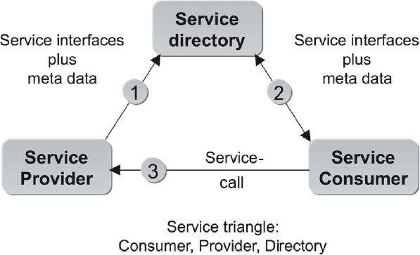
Figure 3-21SOA
Services in general provide low-granularity interfaces. The term low-granularity is used when a service enables complex functionality with only a few calls.
Ideally, these services are stateless, transactionally self-contained, and idempotent—in other words, no matter how often they are called with the same input data, they always deliver the same result.
Services consist of a contractual service interface (for linking the service consumer to the service provider) and the service implementation. The service implementation does not form part of the contract and is replaceable as long as the interface commitments are complied with.
Services are independent of location, and can be activated at any time and from any location, provided consumers and applications have appropriate access rights (“location transparency”).
3.6.4.3Modularization
Modularization is the term used to describe a reasonable degree of decomposition into and arrangement of a software system into subsystems and components. The core task when modularizing is to subdivide the overall system into components that can then be used to map the logical structure of the application. The aim of modularization is to reduce the complexity of the system via the definition and documentation of clear boundaries.
Combing different tasks within a system increases it susceptibility to errors. Unwanted side effects in areas that are not logically related to the task being performed are difficult to retrace and correct.
Individual modules are created that serve as containers for functionality and areas of responsibility. System coupling takes place via clearly defined interfaces that describe the relationship between the modules. Functional appropriateness, completeness, and simplicity are the partially conflicting goals of module creation.
In contrast to a layered architecture, modularization allows creation of individual vertical systems and separated areas of responsibility.
3.6.4.4Microservices
Microservices are an important architectural pattern for the creation and integration of distributed systems. This approach involves structuring large systems into small functional units. Each microservice should represent a different functional unit. Microservices are extensively decoupled and run independently. In contrast to self-contained systems that shouldn’t talk to each other, microservices can communicate with each other both synchronously and asynchronously. Microservices are developed separately and are put into productive use independently of one another.
3.7Design patterns
In addition to architectural patterns, design patterns also play an important role in software architecture. Both types of pattern usually present structural and technical solutions.
Whereas architectural patterns typically assist in the decomposition and composition of components, design patterns are more often used to support the implementation of functionality.
However, the boundary between the two categories is blurred.
The best-known design patterns are described by the “Gang of Four” (Gramma, Helm, Johnson, and Vlissides) also known simply as GoF. The Adapter is a GoF pattern that assists with translation when two classes cannot communicate with each other due to interface incompatibility.
The Proxy is a structural pattern. It controls access to the actual object by providing an identical interface and a reference to the object.
The Facade serves as a simplified interface to a subsystem. Subsystems often include many classes and methods that are not used by the outside world that remain hidden. In this case it helps to use a facade.
3.7.1Adapter
If you wish to use an already existing module whose interface is incompatible with your required interface, the adapter pattern can help.
The adapter is used to adapt the interface.
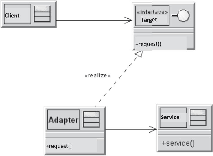
Figure 3-22Adapter
3.7.2Observer
You should use this pattern if a component should be capable of notifying other components without having to know what the other components are or how many components have to be changed.
An observer should react to a state change in a subject without the subject knowing the observer.
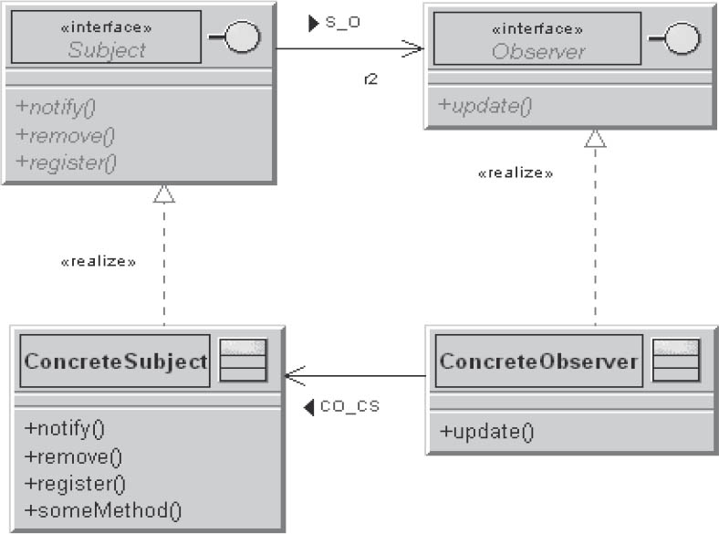
Figure 3-23Observer
The only thing the subject knows about its observers is that they implement the observer interface. There is no fixed link between the observer and the subject. Observers can be registered and removed at any time. Changes to the subject or observer have no effect on each other, and both can be reused independently of one another.
3.7.3Decorator
A decorator dynamically and transparently adds new functionality to a component, without expanding the component itself.
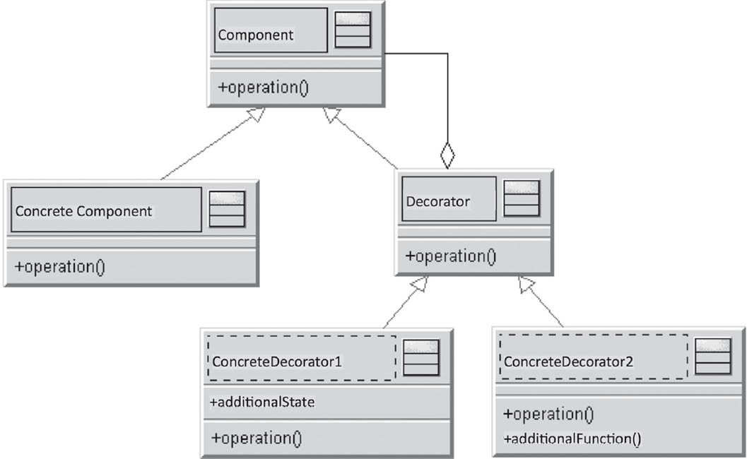
Figure 3-24Decorator
An instance of a decorator is inserted before the class to be decorated, and has the same interface as the class to be decorated. Calls are now forwarded or processed by the decorator, and the caller does not know that a decorator has been inserted. One or more specific decorators define and implement various special decorations.
3.7.4Proxy
A client has to access the operations of an instance of a particular class. However, it may be that direct access to the operations of the class is impossible, difficult, or inappropriate—for example, if direct access is insecure or inefficient, or if you are working in a distributed environment. In this case, it may not be desirable for the physical network address (for direct access to a distributed object) to be hard-coded in the client. However, without this address direct access via the network is not possible.
In cases like this the proxy pattern can be of assistance. Instead of communicating with the class in question, the client communicates with a proxy. The proxy offers the same interface as the instances of the class to be called, while internally, the proxy forwards the call to an instance of this class.
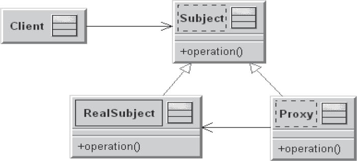
Figure 3-25Proxy
- The client is the object that accesses the real subject via the proxy.
- The proxy provides the same interface as the real subject to the outside world.
- The subject defines the common interface of the proxy and the real subject, and enables the use of proxies instead of real subjects.
- The real subject is the object represented by the proxy.
3.7.5Facade
A facade is another way of reducing dependencies between system components.
With the aid of a facade, the internal components of a subsystem are made invisible to the outside world. It represents a simplified interface to a complex subsystem.
This pattern is useful if, for example, the subsystem contains a large number of technically oriented classes that are rarely or never used by the outside world.
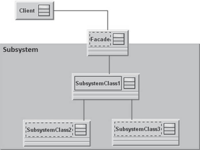
Figure 3-26Facade
3.7.6Bridge
A bridge in the context of software development is a design pattern and belongs to the structural patterns category.
This pattern serves to separate the implementation from its abstraction (interface), allowing both to be changed independently of each other.
Usually, an implementation is realized via inheritance of the abstraction. This, however, can result in the inheritance hierarchy containing both implementations and other abstract classes. This increases the complexity of the inheritance hierarchy and makes it difficult to maintain.
If the abstract classes and implementations are managed in two different hierarchies, this not only increases clarity but also makes the application independent of the implementation.
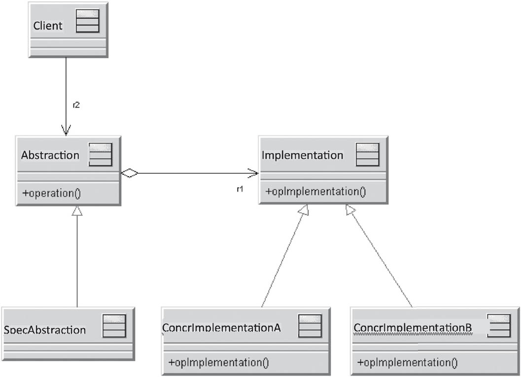
Figure 3-27Bridge
3.7.7State
This pattern serves to encapsulate different, state-dependent behaviors of an object. The behavior of an object usually depends on its state. The normal implementation in large switch statements should be avoided by implementing each case of the switch statement in a separate class. This way, the object’s state once again becomes an object.
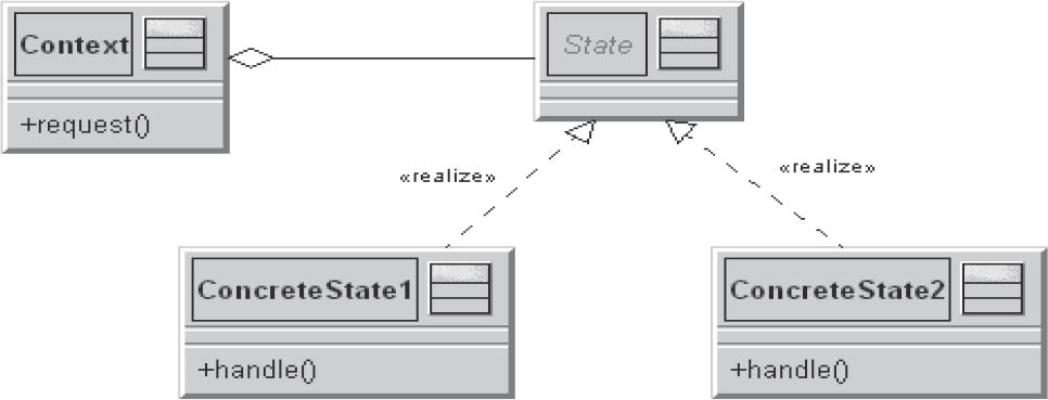
Figure 3-28State
3.7.8Mediator
The mediator is an arbitrator and controls the cooperative behavior of objects. The objects don’t cooperate directly with one another, but instead via the mediator.
The components participating in an interaction are referred to as colleagues. They know the mediator with which they are registered as interaction partners.
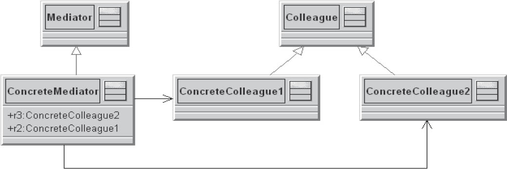
Figure 3-29Mediator
A specific mediator encapsulates complicated interactions between a number of specific components.
Communication control between the components takes place in a single location, which increases comprehensibility and simplifies maintenance.
3.8Test your knowledge
Here are some detailed excerpts from the Designing software architectures section of the iSAQB curriculum [isaqb-curriculum] to help you consolidate what you have learned.
 LG2-1:Select and adhere to approaches and heuristics for architecture development
- Fundamental procedures of architecture development
- Model and view-based architecture development
- Model-based and domain-driven design
- Iterative and incremental design
- Top-down and bottom-up design
- Influencing factors and constraints as limitations in architecture design (global analysis)
 LG2-2:Design architectures
- Designing and appropriately documenting architectures on the basis of known functional and non-functional requirements for software systems that are neither security- nor business-critical
- Recognizing and justifying mutual dependencies of architecture decisions
- Making structure decisions in respect of system decomposition and building block structure, and defining dependencies and interfaces between the building blocks
- Being able to explain the concepts “black box” and “white box” and apply them for specific goals
- Use of stepwise refinement (hierarchical decomposition) and detailed specification of building blocks
- Designing individual architecture views—in particular deployment, building block, and runtime views—and their consequences for the associated source code
- Definition of the mapping of the architecture to the source code, and evaluation of the associated consequences
- Justification and application of separation of functional and technical elements in architectures
- Designing and justifying functional structures
- Understanding the strong influence of non-functional requirements (ease of modification, robustness, efficiency, and so on), and taking this into account in architecture and design decisions
 LG2-3:Identify and consider factors influencing software architecture
- Determining and taking into account the constraints and influencing factors as limitations on design freedom
- Being aware of and taking into account the influence of quality requirements and technical decisions and concepts on architectures
- Being aware of and taking into account the (possible) influence of organizational structures on building block structures
 LG2-4:Deciding on and designing cross-cutting concepts
- Deciding on and, where necessary, implementing cross-disciplinary technical concepts
- Identifying and evaluating possible mutual dependencies of these (technical) decisions
 LG2-5:Describe, explain, and appropriately use important architectural patterns and architectural styles
- Data-flow and data-centric architectural styles
- Hierarchical architectural styles
- Architectural styles for interactive systems
- Heterogeneous architectural styles
- Architectural styles for asynchronous or distributed systems
- Other architectural patterns and styles
- Important sources for architectural patterns
 LG2-6:Explain and use design principles
- Information hiding
- Coupling and cohesion
- Separation of concerns
- The open/closed principle
- Dependency inversion via interfaces
- Dependency injection for externalization of dependencies
- The relationships between dependencies in the model and in the source code of programming languages
 LG2-7:Planning dependencies between building blocks
- Understanding dependencies and the coupling between building blocks, and using them for specific goals
- The ability to list the types of coupling (structural, chronological, via data types, via hardware, and so on)
- Recognizing the consequences of coupling.
- Awareness of ways to remove or reduce coupling
- Implementation of relationships in (object-oriented) programming languages
 LG2-8:Designing the building blocks/structural elements of a software architecture
- Knowledge of the desirable properties of building blocks and structural elements (encapsulation, information hiding, limited access)
- Black box and white box building blocks
- Types of building block composition (nesting, use/delegation, inheritance)
- UML notation for different building blocks and their composition
- Packages as a semantically weak form of building block aggregation
- Components with firmly defined interfaces as a more semantically precise form of aggregation
 LG2-9:Design and define interfaces
- Awareness of the importance of interfaces, and the ability to design and define interfaces between architectural building blocks
- Awareness of the desirable properties of interfaces
- Definition of interfaces, in particular external interfaces
- Specification and documentation of interfaces
 LG2-1:Select and adhere to approaches and heuristics for architecture development
 LG2-2:Design architectures
 LG2-3:Identify and consider factors influencing software architecture
 LG2-4:Decide on and design cross-cutting concepts
 LG2-5:Describe, explain and appropriately use important architectural patterns and architectural styles
 LG2-6:Explain and use design principles
 LG2-7:Plan dependencies between building blocks
 LG2-8:Design architecture building blocks/structural elements
 LG2-9:Design and define interfaces


