4Description and Communication of Software Architectures
Chapter 2 introduced a number of basic software architecture terms as well as the core tasks of a software architect. One of the most important of these tasks is the specification (i.e. documentation) and communication of the software architecture to its stakeholders. Software architects primarily learn via verbal communication what they need to document in writing—in other words, the written description/documentation and verbal communication complement each other.
This chapter provides you with an overview of the tools required for describing/documenting software architectures for their stakeholders in accordance with the iSAQB curriculum.
The following topics are covered in this chapter: Views of software architectures as defined by the iSAQB; template-based, uniformly structured architecture documentation; contents and descriptive elements of the iSAQB views; cross-cutting concerns in software architectures; common document types for describing software architectures; best practices for documentation; and brief overview of selected architecture frameworks.
For the software architectures described in this chapter, we will primarily address the functional (A-architecture) and the technical (T-architecture) levels as defined in Chapter 2. In the following sections, the term “architecture” always refers to software architecture.
More detailed information on these and other topics can, for example, be found in [Clem03], [Sta11], [RH06], and [DE++09].
4.1Integration with the iSAQB curriculum
An extract from the Documentation and communication of software architectures section of the iSAQB curriculum [isaqb-curriculum] is provided below.
4.1.1Learning goals
 LG3-1:Explain and consider quality attributes of technical documentation
 LG3-2:Describe and communicate software architectures
 LG3-3:Understand how to explain and apply notations/models that describe software architecture
 LG3-4:Explain and use architectural views
 LG3-5:Explain and use the system context
 LG3-6:Document and communicate cross-cutting architectural concepts
 LG3-7:Describe interfaces
 LG3-8:Explain and document architectural decisions
 LG3-9:Understand the use of documentation as written communication
 LG3-10:Know additional resources and documentation tools
4.2The CoCoME example
This chapter uses the CoCoME application as its main example. CoCoME stands for Common Component Modeling Example (see also [CoCoME], [RR++08]). CoCoME is designed to provide a benchmark for component-based architecture approaches. To this end:
- a) A publicly accessible implementation of the application is available. It includes both an information system and an embedded system. The implementation attempts to realize current architecture approaches (such as layered and bus architectures) but nonetheless remains small enough to make it simple to understand.
- b) A UML-based description of the CoCoME architecture is also available. The views defined by the authors have also been used for the architecture description.
In [RR++08] more than 15 individual groups describe the application, in each case using their specific architecture approach. This provides an excellent basis for comparing the different architecture approaches.
From our point of view, CoCoME is well-suited for illustrating the concepts and approaches introduced in the following sections. We begin with a short introduction to the application.
4.2.1Use cases in the CoCoME system
CoCoME is an application system for a supermarket chain. Its first major task is to cover the core functionalities of the supermarket checkouts (see figure 4-1). These are the actual sale at the checkout (with use case UC 1: ProcessSale) and the automated reconfiguration of the checkouts. If in the past 60 minutes more than 50 % of all sales were comprised of less than eight products and the customer paid cash, then the checkout reconfigures itself to become an express checkout (UC 2: ManageExpressCheckout). This means the customer can then only use that checkout with a maximum of eight products and must pay cash.
CoCoME’s other major task includes use cases for the management of goods in stock—for example, price management (UC 7: ChangePrice). UC 5: ShowStockReports provides an overview of the goods in stock in the supermarket. UC 3: OrderProducts enables ordering of goods, and UC 4: ReceiveOrderedProducts is used to accept delivered goods into the supermarket’s warehouse.
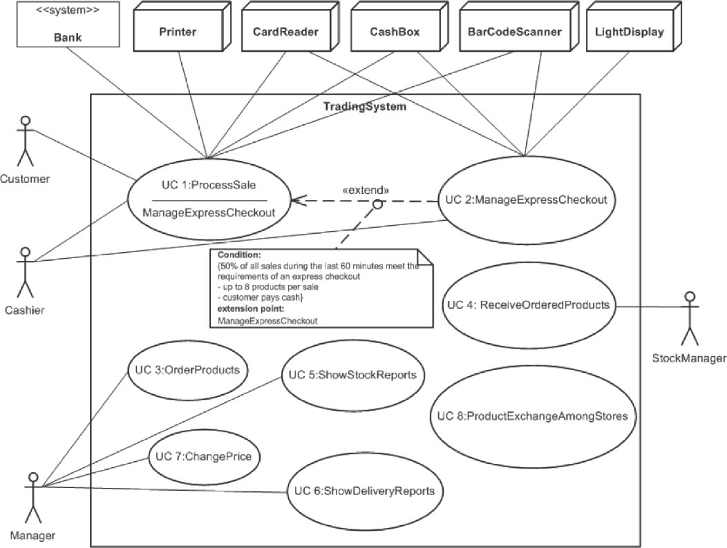
Figure 4-1Central use cases in the CoCoME system
Since a chain of supermarkets is involved, there are also use cases that operate at company level (i.e., beyond the boundaries of the individual supermarket). For example, UC 8: ProductExchangeAmongStores makes suggestions for relocating stocks if specific products start running out in one supermarket, while there are sufficient stocks available in others. UC 6: ShowDeliveryReports provides information on the times required by different suppliers to deliver goods.
4.2.2Overview of the structure of the CoCoME system
As shown in figure 4-2, the CoCoME system is structured hierarchically on three levels: checkout, supermarket, and supermarket chain. The checkout is connected to a number of external hardware components that it controls (printer, card reader, cash till, barcode reader, express lamp). The checkout also has an interface to banking providers for card payments.
All checkouts are connected to a central server where the supermarket’s merchandise management takes place. If, however, the link between checkouts and the supermarket server goes down, the checkout must not stop providing its service. The checkouts are therefore designed so that they can operate autonomously if necessary. This means the checkouts have to manage a local copy of the product and price data. In addition, they also have to temporarily store relevant data on goods sold and synchronize themselves with the server at predefined points in time.
The same naturally also applies to the connection to the chain’s central server. This server monitors goods received and sales in the individual stores, controls the logistics at company level, and manages suppliers. If, however, the link to the company server should be temporarily down, the individual stores must be able to act autonomously.
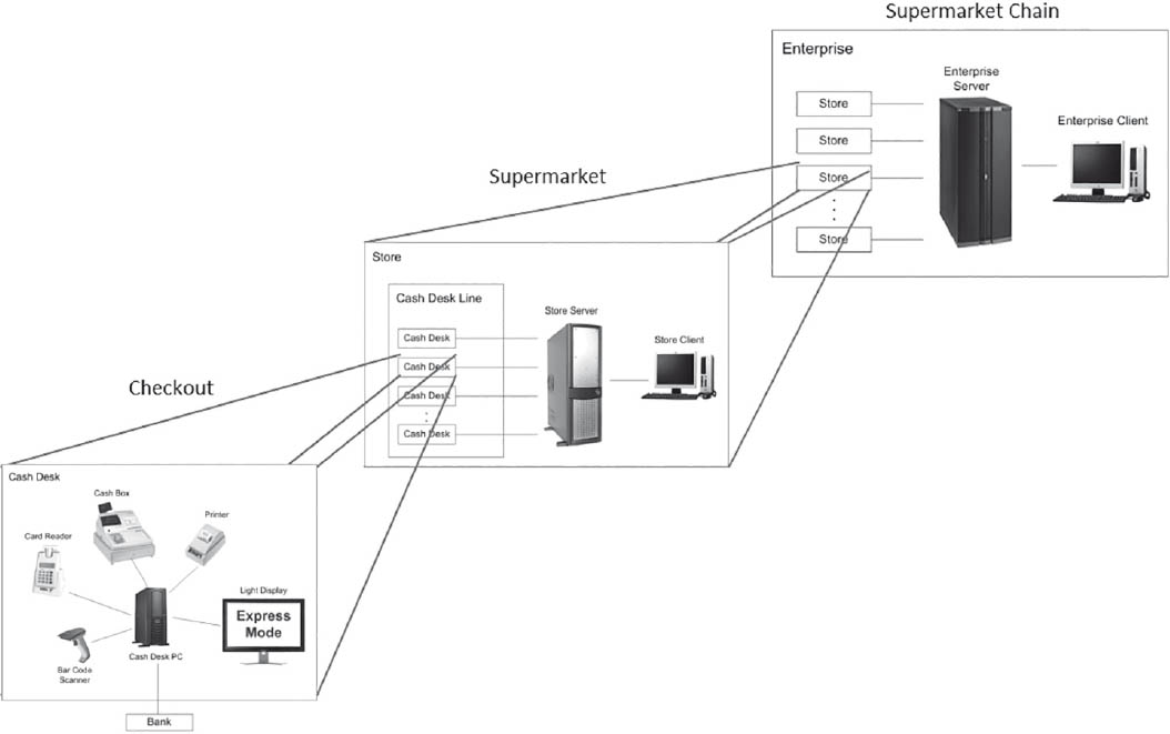
Figure 4-2Overview of the structure of the CoCoME system
4.3Views and templates
As we have already seen in Chapter 2, the term “architecture view” is frequently used in the context of software architecture descriptions. An architecture view is a representation of the system from a specific viewpoint. It emphasizes important features of the object being viewed, and creates high-level abstractions that obscure the details that are not of significance for this specific point of view. At this stage we want to provide you with an overview and initial guidelines on how to meaningfully describe architecture views.
The views addressed in this chapter (context view, building block view, and so on) have already been covered in Chapter 2. We will often refer to them simply as “views”. In addition, we assume that you are already familiar with acronyms such as UML and ER.
4.3.1Well-established views as defined by the iSAQB
Software architecture literature offers a range of different approaches to describing software architectures, many of which use the concept of views.
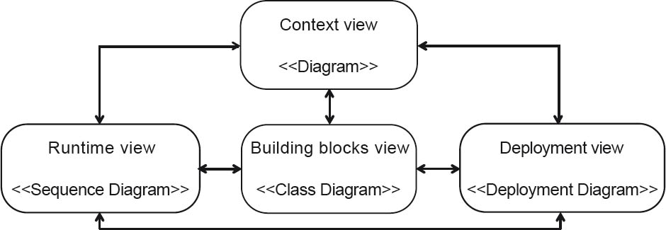
Figure 4-3Proven views as defined by the iSAQB
Within the framework of the iSAQB curriculum, four key views are addressed. These are regarded as proven and have particular practical relevance. They are based on pragmatic software architecture descriptions in line with the template in [ARC42], which in turn is derived from the “4+1” model for software architectures [Kru95]. These four views and the interactions between them are shown in figure 4-3. The views are:
- Context view (or context diagram)
A diagram with (preferably) UML components, the system under design as a black box, and all external systems and users as actors or UML components. Distribution or deployment context are correspondingly notated using UML node symbols.
- Building block view
UML component diagrams or top-level class diagrams of the functional and (possibly) technical “software building blocks” of the software system and their relationships to each other
- Runtime view
Sequence, activity, or similar diagrams for illustration of the main (or key) sequences, in particular those between the building blocks that make up (or lie within) the software systems
- Deployment view (or infrastructure view)
Deployment of system software artifacts to computer nodes, networks, and so on—in other words, mapping of the software to the physical technical infrastructure
These four views often provide an adequate basis for describing a software architecture. Other specialized views, however, can usefully supplement these—for example, if they enable you to explain things better to your stakeholders. Some examples of specialized views are:
- Data view
A detailed description of the database structures of a software system—for example by means of an Entity Relationship (ER) model
- “Big Picture”
A view of the high-level system architecture for communication with management (i.e., budget approval)
- Mask (or sequence) view
Screen masks, website screen sequence diagrams, and similar
For each additional view, you need to take the effort involved in creation and maintenance into account. The total documentation effort will be correspondingly larger. A detailed explanation of any additional diagram symbols may also be required.
All types of views can exist more than once for elaborating parts or sub-areas of a software system. Their use must be determined based on the stakeholders, the criticality of the system, and the complexity of specific parts of the system.
4.3.2UML diagrams as a notation tool in view descriptions
The Unified Modeling Language (UML, see [UML-1a], [UML-1b], [UML-1c], [RQ+12], [Oes09]) notation can be used for presenting diagrams within view descriptions. This is useful because—since its standardization by the Object Management Group (OMG) in 1997—UML notation is extensively used in practice. You can thus expect a high level of familiarity with basic UML elements within your target group (you should nonetheless always check this before using UML excessively). As a brief recap, this section covers some of the important UML diagrams for software architectures (which you can skip if you are already familiar with UML).
Diagram types in UML 2
Version 2.3 ([UML-1b], [UML-1c]) was released in 2010 and contains a total of 14 types of diagrams (seven structure diagrams and seven behavior diagrams). These are listed in the table below. UML diagrams that we consider particularly important for view descriptions in software architectures are written in bold type.
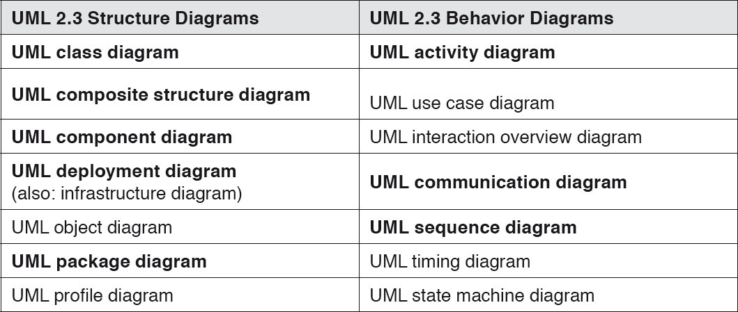
Table 4-1UML 2 diagram types
The following sections detail two UML structure diagrams and two UML behavior diagrams.
UML class diagram
UML class diagrams show the static structure of classes and relationships between classes. Typical relationships are associations, aggregations, specializations, and generalizations (see figure 4-4). Relationships can have different cardinalities—for example, you will find 1:1, 1:n, and m:n relationships.

Figure 4-4UML class diagram with different types of relationships
UML component diagram
UML component diagrams provide an overview of the building blocks that make up a software system and describe them using UML components. UML components have well-defined interfaces via which they are connected to other system components. Figure 4-5 shows two UML components that are connected via an input and an output interface.

Figure 4-5UML component diagram
UML activity diagram
UML activity diagrams show possible sequences within elements of the system (for example: classes, components, or use cases). These diagrams can be used to provide detailed descriptions of algorithms, data flows, and control flows. Figure 4-6 shows a sequence with a start point, an end point, sub-steps, and branching.
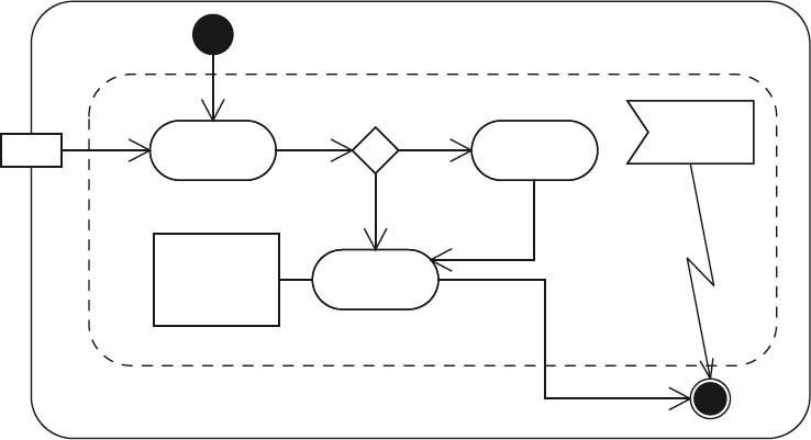
Figure 4-6UML activity diagram
UML sequence diagram
UML sequence diagrams show interactions (message exchange) between instances of building blocks in a software system. To prevent individual sequence diagrams from becoming too large, they can be nested. In figure 4-7, two building block instances exchange messages, and an additional building block instance is addressed via a nested diagram.
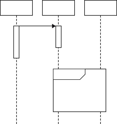
Figure 4-7UML sequence diagram
Conclusion: UML for diagrams in view descriptions
UML is a widely used, extensive tool with many different types of diagrams for describing software systems. You should not, however, regard UML as a universal solution that always works. Don’t hesitate to supplement diagrams when it helps your target group to understand things better. Other types of diagrams, such as informal “boxes and arrows”, are often used to describe software architectures. It is particularly important to explain the symbols used in such non-standard diagrams.
UML can also be inappropriate for some groups of stakeholders. Other diagrams can, for example, be useful for communicating the architecture at the management level (the “big picture”). PowerPoint slides, for example, can perhaps be combined with Visio diagrams of high-level network symbols and informal “boxes and arrows” diagrams. Event-driven Process Chain (EPC) diagrams for (high-level) process workflows and the like can also be useful at this level.
Correspondingly, entity relationship diagrams are often more suitable for describing databases, while diagrams with network symbols are better when describing administrative and operational aspects.
4.3.3View description: high-level structure and an example
This section provides a high-level overview of the structure of view descriptions. A template for software architecture descriptions (including view descriptions) is provided in [ARC42]. Such templates can, however, also be found in a range of other approaches—for example, in RM-ODP [RM-ODP]. A brief example is provided in Section 4.3.3.2.
4.3.3.1High-level structure: template-type view description
When describing software architectures and, in particular, architecture views, it makes sense to use a standard structure or layout. This provides a high recognition value for readers. It’s also important to match the description to the respective target group. Ask your stakeholders which aspects need to be described for their own particular tasks.
When describing architecture views, the rule of thumb is to use as little formalism as possible, but as much as necessary. A project shouldn’t have to go way off schedule simply because architecture diagrams are only accepted when every little detail has been addressed. As an architect, you should resist the temptation to act dogmatically.
A useful initial framework for the scope of the documentation is the risk level or the complexity of the building blocks to be described. The higher the risks, the more comprehensive the building block documentation will have to be. If the risk levels are manageable, some details can be omitted.
Sample sections for describing architecture views could look as follows:
- Brief description
The brief description of the view provides a short text-based overview of “what is involved in this specific case”.
- Diagrams
Diagrams provide a graphical representation of the view.
- Element catalog
- Elements and their properties)
- Relationships and their properties
- Interfaces of and between elements
- Element behavior
If an element catalog covering all the diagrams is too unwieldy, multiple local element catalogs can be used for the diagrams of a view.
- Variability
This section uses a text-based description to address the issue of variable elements or relationships within the view. All variabilities in terms of requirements, architecture, design, involved external systems, or infrastructure are included herein.
Depending on the type of view, configuration, installation and operating parameters can also be explained here. A list of all the technological standards to be complied with can also be provided here.
Within the variabilities, it can be useful to differentiate between changeability and flexibility. Changeability addresses foreseeable ability to modify the current system (for example, changing the JDBC database driver), while flexibility addresses the ability to extend the system (for example, by providing extension stages that permit different types of GUI access to the same underlying application).
- Background information
Text-based background information is important when it comes to understanding the specific structure of a view and can be used to justify specific design decisions. Typical background information includes:
- Justifications for the selected structure or the chosen alternative
- Results of analyses or preliminary assessments of specific content-related system aspects
- Assumptions made in respect of the system, building blocks in use, or the system environment
- References to associated or connected views
- Miscellaneous source information or sample code
4.3.3.2Example: Excerpt from a view description for a building block view
By way of illustration, an excerpt from the building block view of the CoCoME example is provided below.
Brief description
This section from a building-block view presents an overview of CoCoME for the operation of a supermarket checkout. Figure 4-8 uses a UML composite structure diagram to show the topmost building block level of CoCoME with the software building blocks Inventory and CashDeskLine, both of which are represented by UML components1.
Diagram
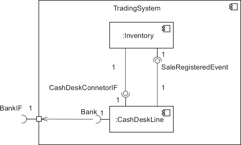
Figure 4-8Building block view of CoCoME, topmost level
Element catalogue of the CoCoME building block view (TradingSystem)
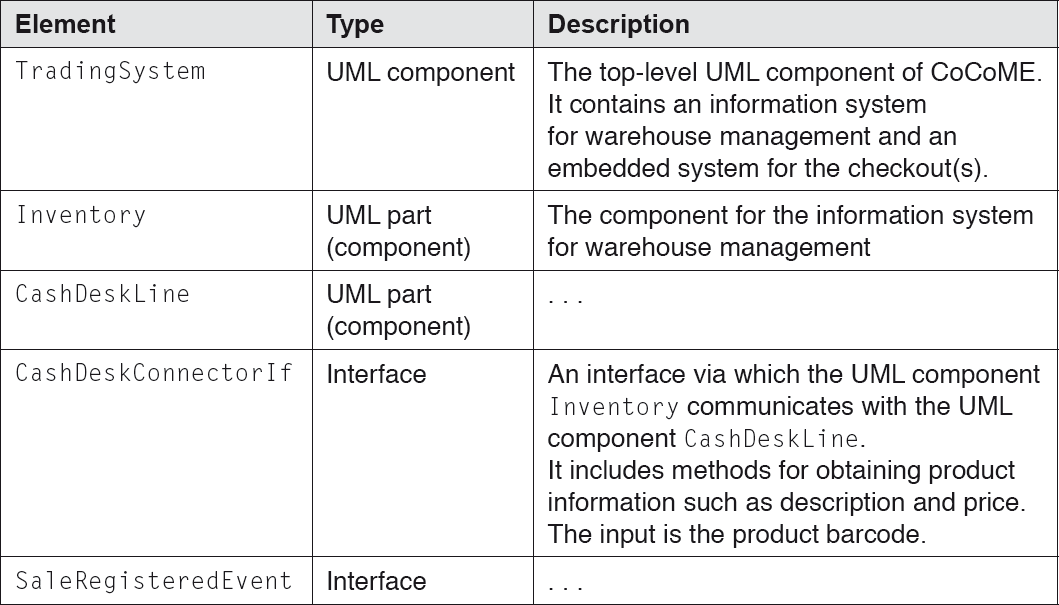
Table 4-2Element catalogue of the CoCoME building block view
Variability
Cash register systems shall be capable of being configured for differing installations. Specific plausibilities will then apply.
Background information
- Analyses
- Prototypes have shown that the barcode scanner in CoCoME could represent a source of errors. For this reason, appropriate tests are to be carried out during development, and measures are to be implemented in the final system to ensure increased fault tolerance in this area.
- Clarification with the responsible stakeholders is still required with regard to whether the CoCoME software should really be configurable down to the local level. Where appropriate, measures for evaluating prototypes are to be implemented by CoCoME test users.
- Assumptions
- No particular error sources, security risks, or performance bottlenecks can be expected from other CoCoME building blocks.
- References to associated views
- Refined CoCoME building block view
- Runtime views and deployment/infrastructure view
Based on this high-level structure and the sample excerpt of a view description, we will now present the four views listed in Section 4.3.1, starting with the context view.
4.3.4Context view (or context diagram)
Contents of the context view
The context view (also referred to as the context diagram) is an important link between the text-based/graphical requirements description and the subsequent architecture. It describes the environment of a system and the relationships and connections with this environment, and thus provides all involved parties with an entry point and a map for the system.
In the context view description the emphasis is therefore placed on interfaces to adjacent systems. For a more detailed description of the functional, technical, and organizational aspects of the implementation of these interfaces, reference should be made to the corresponding interface concept.
The following elements are important in the context view:
- External actors (adjacent systems and users)
- The system to be developed
- All interfaces to external actors (all adjacent systems and users) including:
- The type of interface (for example, online, batch, USB, or file), the data or resources passed via this interface, and any services or functions used
- Communication protocols used
- Communication patterns used (for example, synchronous, asynchronous)
On this basis, the context view delimits the scope of the software system in question.
Context view stakeholders
The interfaces to adjacent systems are one of the most critical aspects of a project, so the context view is correspondingly important. Context view stakeholders often include:
- Project management
- Requirements analysts (as “input providers”)
- System analysts (as “input providers”)
- Technical or domain experts (as “input providers”)
- Design and development
- Testers
- (Perhaps) downstream administration and operations
- Controlling (assignment of the development costs to cost centers)
- In the case of “products”, perhaps sales and marketing
- <you-name-it> – (i.e., any others, depending on the organization and the project)
Typical descriptive elements in the context view notation
Descriptions of the context view are primarily made using
- Context diagrams
- Lists of adjacent systems with their interfaces
The context view is often both functional and technical. A software system description can thus be functionally delimited from other software systems while being technically integrated into existing or future infrastructures.
The functional element of a context view can be either static or dynamic. The dynamic view tends to be more suitable for test and operations, while the static view is better for architecture, design, and development. In the following sections, we will concentrate on the static view.
It is essential that all relevant aspects of the interfaces be specified in the context view. For example, what is passed through the interface, the format it is passed in, the medium used, and so on—even though several popular diagram types (such as the UML use case diagrams) only illustrate specific aspects of the interface.
Context view diagrams are created using many different notations. If UML diagrams are used, then UML component diagrams and UML composite structure diagrams are particularly useful for functionally-oriented diagrams of this view. In this case, it is appropriate to position the system to be described as the “black box at the center” with well-defined interfaces.
In the case of technically-oriented context views, you can also supplement UML components using UML nodes. UML package symbols are sometimes used for this purpose too. Non-UML network symbols (for example, those used by Visio) are frequently used. Other less formal forms of notation in the PowerPoint “boxes and arrows” style are often used in the context view. The important thing to note is that the representations used are appropriate for communication with your main stakeholders.
The context view provides abstract illustrations of the building block, runtime, and deployment views, so their respective notations and diagrams can also be used to supplement those of the context view itself.
The context view usually contains the following elements:
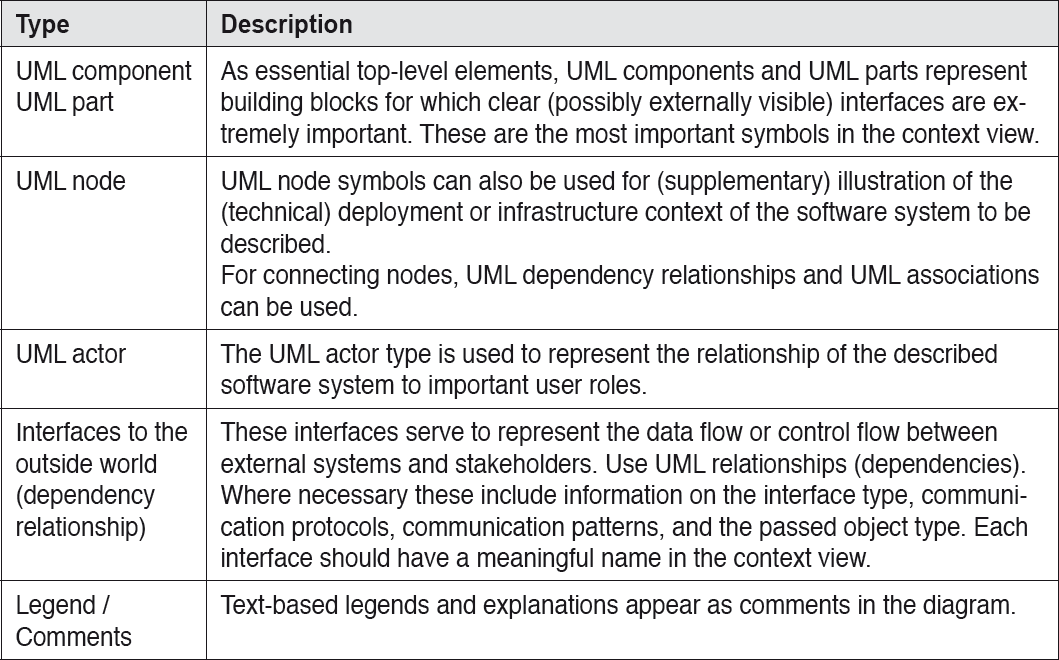
Table 4-3Elements of the context view
Examples of diagrams from a context view
The following sections show sample context view diagrams from CoCoME, some of which use non-UML description methods.
To begin with, figure 4-9 shows the context of a single cash desk in a simple diagram that consists only of “symbols and lines”. The central element here is the Cash Desk PC, which represents a connection to a bank and to the various hardware building blocks that form a cash desk. These include a Bar Code Scanner for identification of products to be billed, a Card Reader for credit/debit cards, the Cash Box, a printer, and a monitor. All of these hardware building blocks have interfaces that are addressed by the Cash Desk PC. This PC thus interacts with its surrounding environment via these interfaces.
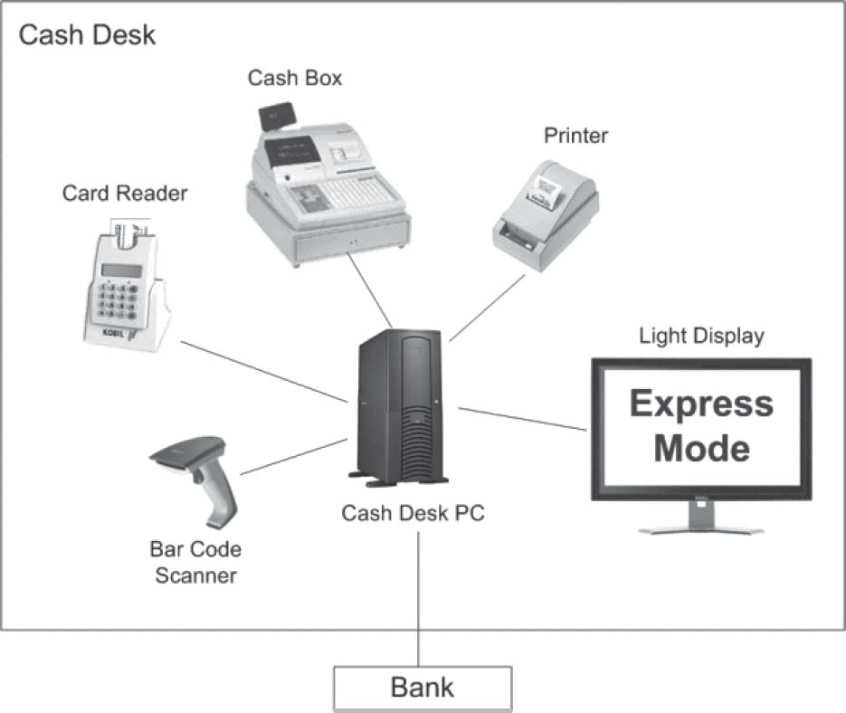
Figure 4-9The context of a cash desk
Figure 4-10 shows the cash desk in the context of a Store. At the left of the corresponding UML diagram we see a UML component called CashDeskLine, which contains all the CashDesks in the Store. These CashDesks are connected to a StoreServer, which in turn is accessed by a StoreClient.
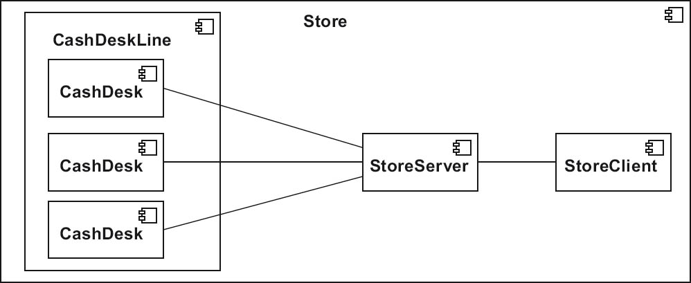
Figure 4-10The context of a cash desk in a store
In figure 4-11, the stores are shown in the context of the company (the Enterprise). The corresponding UML diagram shows several Stores as UML components connected to the company server (the UML component EnterpriseServer), which in turn is accessed by a client (the UML component EnterpriseClient).
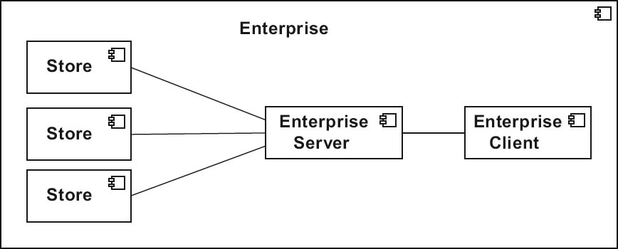
Figure 4-11The context of several stores within the enterprise
4.3.5Building block view
Contents of the building block view
The building block view shows the static structures of a software system. During development, this view details the desired structure, whereas it has to reflect its real-world structure once the system enters production. The objective of this view is to explicitly show the static structure of the software architecture and the relationships between its building blocks.
As already explained and illustrated in Chapter 2, the term “building block” covers all software and implementation artifacts that ultimately represent abstractions of source code. At the topmost level, these include software subsystems or software packages. It should also be noted that building blocks can themselves consist of other building blocks.
It is helpful if each building block has at least the following attributes:
- Name
- Responsibility or purpose
- Interface
- Reference to its implementation
Other optional attributes can also be added—for example, requirements or open issues.
Building block views can be developed using a top-down approach. In this case, the starting point is a context view. If existing systems have to be integrated, a top-down approach may have to be combined with a bottom-up abstraction of these systems. An example of this is the abstraction of basic services within a service-oriented architecture.
Building block view stakeholders
The building block view primarily addresses the design and implementation of a software system. Its stakeholders are:
- All project staff involved in the architecture, design, development and testing of the software
- Quality assurance (if not already directly assigned to the project)
- The building block view assists project management in the development of work and activity plans.
- Following completion of the software development project, the building block view also enables more efficient maintenance of the resulting software.
Descriptive elements of building block view notation
Typical UML elements in the building block view are component and package symbols.
UML component symbols are the most expedient descriptive elements in the building block view, particularly in the case of systems in which external interfaces play a significant role. Widely used alternatives (or supplements) to UML components are the classes of the topmost building block level, which are represented by UML class symbols. Classes are used more prevalently during refinement of the building block view (for more on refinements see Section 4.3.9).
Examples of the use of UML components in the building block view are TradingSystem, Inventory, and CashDeskLine (see figure 4-8).
When using different notation types in diagrams, less is often more. Using UML as an example, in many cases the following elements are sufficient to represent an entire software system and its environment:
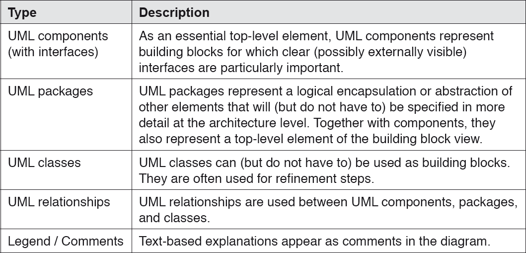
Table 4-4Elements required to represent a software system and its environment
Examples of diagrams from a building block view
As further examples of building block view diagrams, figures 4-12 and 4-13 show refinements of the Inventory building block in figure 4-8.
In figure 4-12, the GUI building block Inventory::GUI (of Inventory) is shown in the form of a UML component. It contains a UML component for Reporting via a reporting interface (ReportingIf), which generates various reports and statistics. In addition, there is the UML component Store, via which a StoreManager can be accessed using a StoreIf interface (for example, to place product orders).
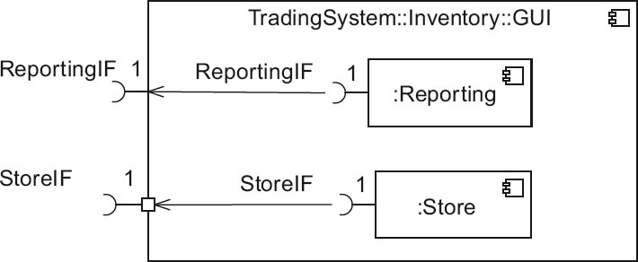
Figure 4-12Building block view refinement – GUI for Inventory
Figure 4-13 shows the internal structure of Inventory in refined form. In addition to the GUI building blocks already referred to, it contains the UML components Application, Data, and Database. Various interfaces for UML components (for example, ReportingIf and StoreQueryIf) are supplemented by important methods such as OrderEntry and ProductOrder.
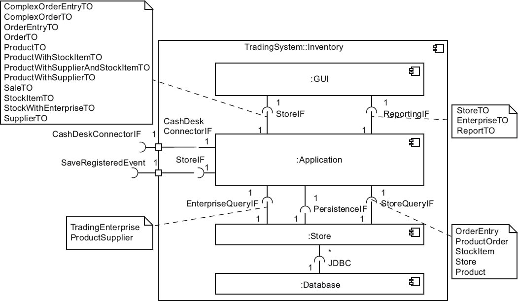
Figure 4-13Building block view refinement – Inventory as a white box
4.3.6Runtime view
Contents of the runtime view
The runtime view describes the interactions between elements2 of the software system at runtime. Here, important aspects of system operation come into play that affect system start, runtime configuration, and system administration. The runtime view does not usually describe the entire software system, but instead focuses on important elements of the system and examples that provide an overview.
Note: An exception to this rule is comprehensive use of model-driven software development. If you want to generate code from your UML diagrams that includes dynamic elements from the runtime view, then these diagrams have to describe the architecture of your software system extensively and precisely.
Runtime view stakeholders
The runtime view has various target groups:
- Operators of the software system
- System architects
- All project staff involved in the design, development, and testing of the software
Quality assurance is also a stakeholder in this view (if not already directly assigned to the project).
Typical descriptive elements of the runtime view notation
The runtime view primarily describes the dynamic interaction of building blocks. Various forms of descriptions are used for this, all of which have specific advantages. Some typical examples are:
- UML activity, communication3 and sequence diagrams
- Traditional flow diagrams can also be a useful notation for the runtime view if they are well understood by your target group.
- In justified cases, small sections of (pseudo)code can be useful.
- Informal verbal sequence descriptions in the form of numbered lists can also be useful. These, however, must be easy to understand and sufficiently short. You also need to make sure that the central semantics of the corresponding sequence are sufficiently clear, and that the assignment of each activity to the corresponding executing building block is clear.
- Business process model and notation (BPMN) is another option for representing business processes in the runtime view.
In some cases, static models are a useful part of the runtime view. For example, if a runtime view of individual instances of objects is to be described, you can use UML object diagrams (or other types) to facilitate this. However, at the architecture level these are not usually necessary, so the focus in the following sections lies solely on elements for dynamic models.
Examples of diagrams from a runtime view
Figures 4-15 and 4-16 show two sample diagrams from the runtime view of CoCoME. The first is a sequence diagram that describes the process of generating a report on current stock levels (Stock Report). For comparison, the second diagram is a communication diagram that describes the same process.
Sequence diagram
Figure 4-14 provides an overview of a number of important elements in a UML sequence diagram.
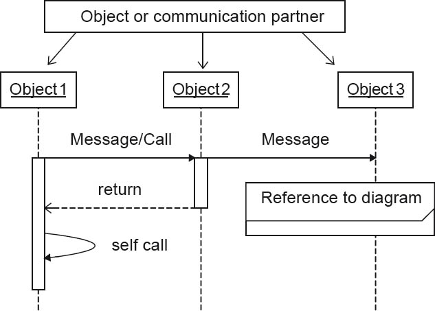
Figure 4-14Runtime view: typical elements of sequence diagrams
Important elements of UML sequence diagrams are listed in tabular form below. Since the release of UML 2, the number of possible elements in these diagrams has increased significantly to include loops, conditions, references to other diagrams, and other elements too. In the interest of simplicity and clarity, the rule of using as few elements as possible applies here too.
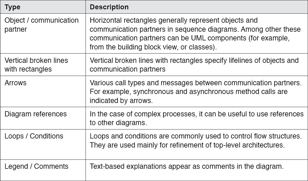
Table 4-5Elements of UML sequence diagrams
Figure 4-15 shows another sequence diagram. It contains typical elements of such diagrams—for example, method calls and a loop.
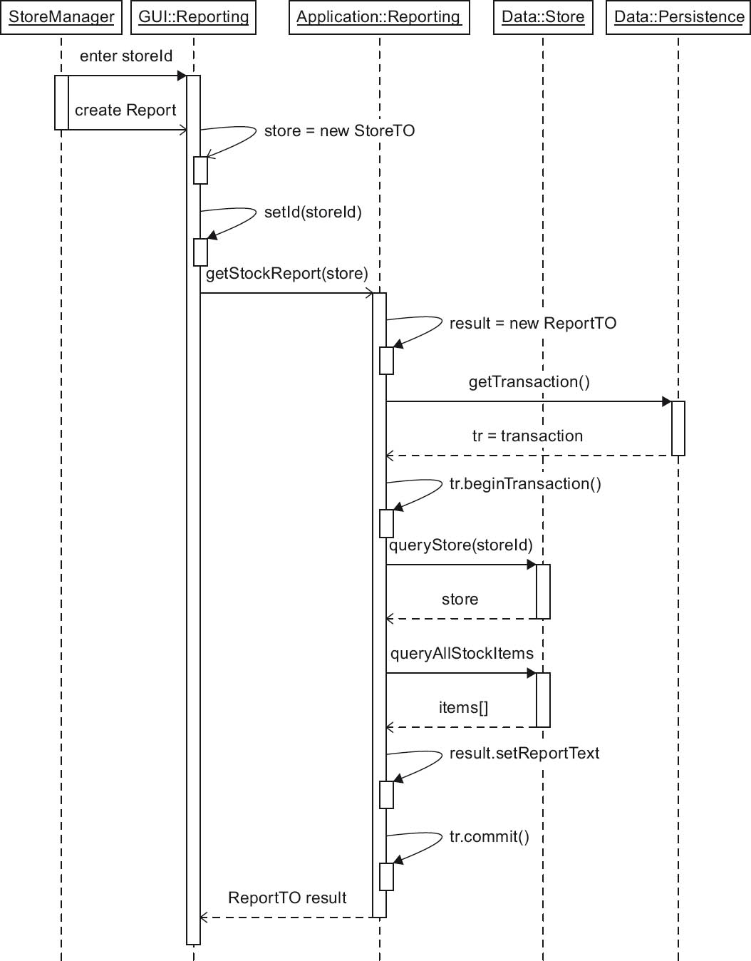
Figure 4-15Runtime view: sample sequence diagram “Stock level report”
The content of this sequence diagram describes the creation of stock level reports. This is a typical CoCoME use case, and describes the following sequence:
A StoreManager can use the UML component GUI::Reporting to check stock levels. The input is a storeId, following which the Create Report action must be selected. The reaction is a call to the getStockReport() method of the UML component Application::Reporting. This in turn accesses the data component Data::Store to create an appropriate report in a loop (the loop is enclosed in a transaction tr.begin . . . tr.commit). As the result, a ReportTO object is generated and returned to the UML component GUI::Reporting. Finally, the result is displayed as a report in the Store Manager GUI.
Communication diagram
In contrast to the compact, tabular left-to-right layout of UML sequence diagrams, the partners involved in UML communication diagrams can largely be freely arranged. This makes it easier to structure the layout—for example, based on the building blocks from the building block view. However, large diagrams that include many communication relationships can easily become unwieldy and confusing.
Figure 4-16 shows the same sequence as figure 4-15, but this time in the form of a UML communication diagram. The increased freedom available in the arrangement of the diagram’s elements is clearly visible.
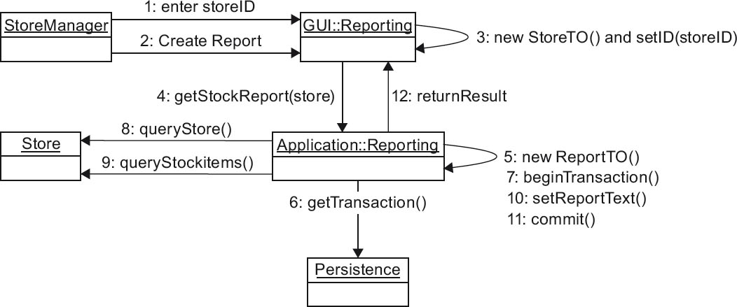
Figure 4-16Runtime view: sample communication diagram “Stock level report”
4.3.7Deployment/infrastructure view
Contents of the deployment view
Deployment views—also referred to as infrastructure views—describe the (technical) environment in which a software system runs. They assist in the operation and deployment of a software system. In this view, specific UML components from the building block view are placed within nodes in the deployment view. These descriptions therefore contain system software or hardware building blocks such as application servers, database management systems, network connections, servers, and so on.
In this view, artifacts (i.e., work results such as documents, files, software, executables, .war, .ear, script, source, library) are generally assigned to “their” execution nodes (for example, a computer, a server, a device, a database/database system/database management system, an EJB container, a container, an OS, a workflow management system). Assignments of this kind can be made on a 1:1 or an m:n basis—in other words, multiple artifacts can be assigned to more than one node.
An additionally useful feature of the deployment view is the specific mapping of the software system to “reality”. For example, this can take place in the form of references to build and deploy scripts (or their descriptions). A separate documentation section may well be appropriate (see also Section 4.5).
Deployment view stakeholders
The deployment view addresses the “real software operating environment”. Its main stakeholders are:
- Operators of the software system (a particularly important target group)
- System architects and software architects
- Developers (to ensure that they know the environment and networks in which their software will run and how distributed the software will run)
Typical descriptive elements of the deployment view notation
The central UML entities in this view are UML deployment diagrams, in which nodes can be used to represent any technical elements. Channels (in the form of associations) are used to interconnect nodes. In addition, UML component and package symbols are used for runtime elements (software systems). Here too, less is often more.
In exceptional cases, it can be useful to refine UML deployment diagrams with network symbols (such as those available in Visio) to provide additional information for specific target groups (for example, network administrators). There are also symbols for tape drives, database systems, mainframes, PCs, servers, and so on. These symbols, however, should only be used as supplements to UML diagrams when you are sure your stakeholders will benefit from their use. In a purely UML context, corresponding stereotypes of UML nodes and components can be used instead, assuming that your specific target group is familiar with this form of notation.
The typical symbols in a deployment view are listed in the table below:
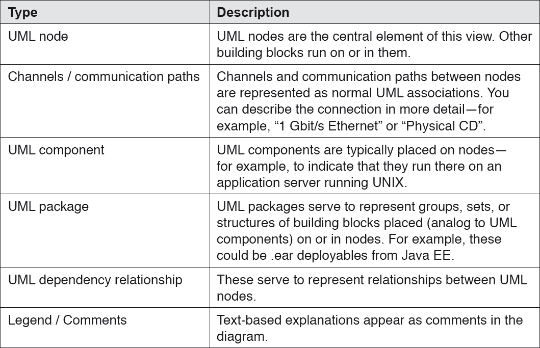
Table 4-6Typical symbols in the deployment view
Examples of diagrams from a deployment/infrastructure view
We will use two sample diagrams to explain the deployment/infrastructure view in more detail.
Figure 4-17 first shows an “enriched”, semi-formal UML deployment diagram for a miniature web shop. It consists of two UML nodes that represent a PC that can access the web shop as a client, and the web shop server. The PC is a standard Windows PC with ≥ 3GB RAM. Two Java deployment artifacts, ShopView.jar and ShopAPI.jar, are installed on it. The runtime environment is Java Runtime Environment (JRE) 1.8.x.
The PC accesses the web shop server ShopServer via a TCP/IP link of unspecified bandwidth. The server runs Sun/Oracle Solaris. It has 8GB of RAM and 1TB hard disk capacity. An IBM DB/2 database is used for managing the shop data.
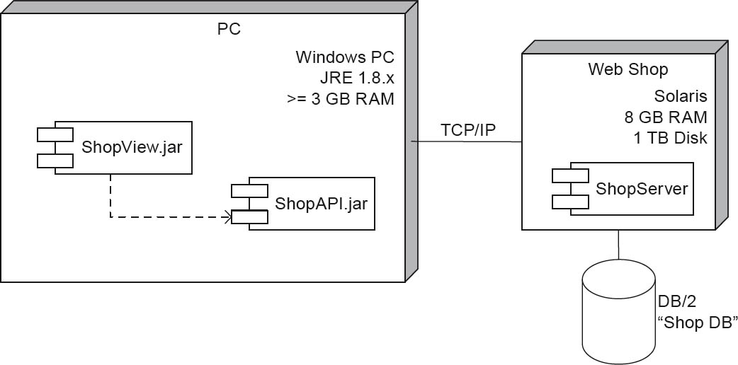
Figure 4-17Deployment/infrastructure view – Web shop deployment diagram
The second diagram (figure 4-18) is a UML deployment diagram that shows an overview of the main physical building blocks in the CoCoME system.
From left to right, we see the UML node CashDeskPC. This UML node contains the UML components CashDesk (the core cash desk software) and a CashDeskChannel. The channel provides communication with the peripheral devices such as Printer, CardReader, Bar Code Scanner, and Display. In technical terms, these devices are connected via RS-232 interfaces. The interface/link to the bank is implemented via Java Remote Method Invocation (RMI).
In the center of the diagram we see the StoreServer node. It contains the four UML components Coordinator, extCommChannel, Application, and Data, along with their UML sub-components. A StoreServer node can be connected to any number of cash desk PCs (CashDeskPC nodes). Java RMI is the technical basis for these connections too.
A StoreServer node can have any number of StoreClient nodes. These are also connected using Java RMI. An Inventory GUI building block (shown as a UML component) runs on each StoreClient node.
At the far right of the diagram we see the company with its EnterpriseServer node, to which any number of StoreServer nodes can be connected via Java Database Connectivity (JDBC). The EnterpriseServer node contains the UML components Database, componentData, and componentReporting. The EnterpriseServer node is accessed by any number of EnterpriseClient nodes, also via Java RMI. An EnterpriseClient node has a GUI UML component for inventory reporting.
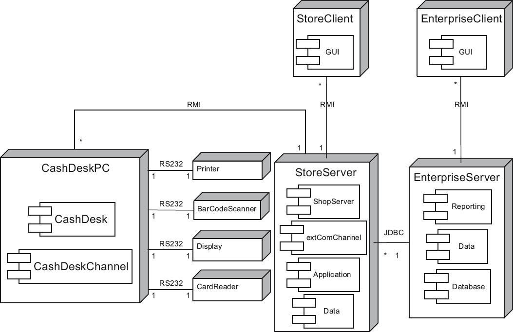
Figure 4-18Deployment/infrastructure view – the complete CoCoME deployment diagram
4.3.8Interdependencies of architecture views
The design of a specific architecture view often has an impact on other views. Changes to one view necessitate adaptations in other views. It is thus desirable to use an iterative development process in which all dependent views are updated following each change. Special interdependencies should be documented for the following reasons:
- Design decisions become more comprehensible.
- The impact of changes becomes more easily recognizable.
- Dependencies between system components are easier to understand.
The following interdependencies exist between architecture views:
- The context views that let the software system interact as a black box with its neighbors.
- The building block view and the runtime view are derived from the context view, and have relationships with one another (i.e., building blocks interact at runtime).
- The deployment/infrastructure view also exists in a (technical) context. The elements of the building block view are placed within the technical nodes and elements of the deployment/infrastructure view.
4.3.9Hierarchical refinement of architecture views
Generally speaking, the architecture level represents a “top-level” description of a software system. It primarily serves two purposes: Firstly, such a description should offer an overall impression of the system as a basis for subsequent, more detailed insight and further refinements4, and secondly, it should provide an abstract (technical) summary of the system that can be used as an entry reference at higher organizational or technical levels.
General explanations of the terms “black box” and “white box” have already been provided in Chapter 2. We will use these terms to explain the hierarchical refinement of architecture views.
The hierarchy fundamentally begins with the context view, which represents the entire system as a black box (i.e., the topmost level). As explained in Chapter 2, a black box shows external interfaces and describes functionality using the principle of information hiding. The topmost level of the hierarchy can thus be clearly assigned to the architecture.
The first level of refinement represents the overall system as a white box. As explained in Chapter 2, a white box shows the inner structure of a building block, with its dependencies and methods of operation. The internal building blocks are in turn black boxes that are subsequently refined.
At this stage, the transition to software system design begins, and is actually quite fluid. The architecture can (but does not have to) further refine the white box descriptions. You should specify important sub-areas in sufficient detail. Figure 4-19 shows a sample hierarchy of refinements in the building block view. It begins with the context view, which initially refines the building block System into building blocks A and B (for simplicity’s sake, the interfaces to AdjacentSystem1 and AdjacentSystem2 have been omitted in the diagram for this first refinement step). Building blocks A and B are then further refined to produce C & D and E & F.
Software system design begins at the latest when a refinement of the modules or components to specific OO classes takes place5. When this stage is reached, the architecture and software system design and development must cooperate particularly closely to avoid subsequent “failures”.
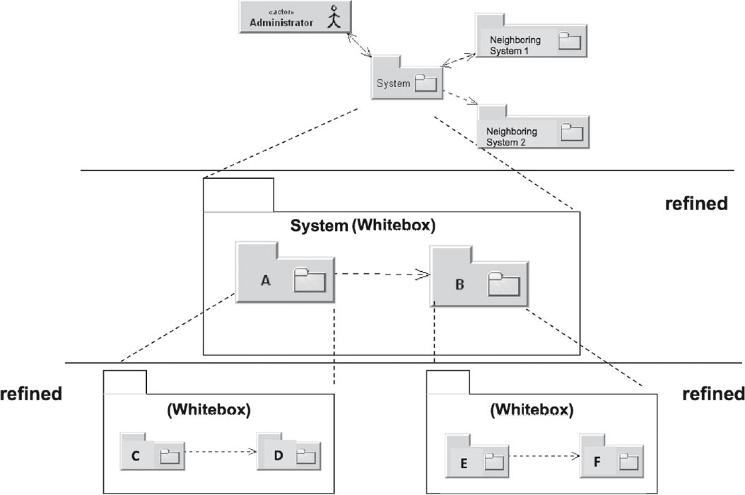
Figure 4-19Hierarchy and refinement of building blocks in the building block view
It should be noted that successive refinement is not restricted to the building block view. The runtime view in particular can be correspondingly refined. In the example shown in figure 4-19, building block A has been refined into building blocks C and D. This could, for example, necessitate a new runtime view diagram that includes communication between the building blocks C and D.
Black box description
For the description of black box building blocks, it makes logical sense to always follow a similar pattern. Typical information used for this purpose is summarized in the table below:
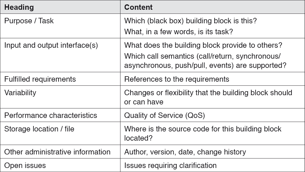
Table 4-7lack box description data
A sample excerpt from a black box building block diagram is provided in figure 4-20. This shows a UML component EmailManagement, which could, for example, be used as an extension for CoCoME. The diagram shows the UML component and several of its interfaces, such as Receive email, Fetch email, Monitor operation, and Send email. How the EmailManagement building block is implemented internally is not explicitly shown.
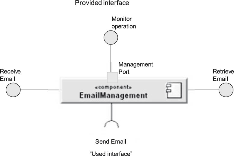
Figure 4-20Black box view of the UML component “EmailManagement”
White box description
When black box building blocks are refined, white box views are created. Use of a defined template is also recommended for white boxes, and the table below details a sample approach:
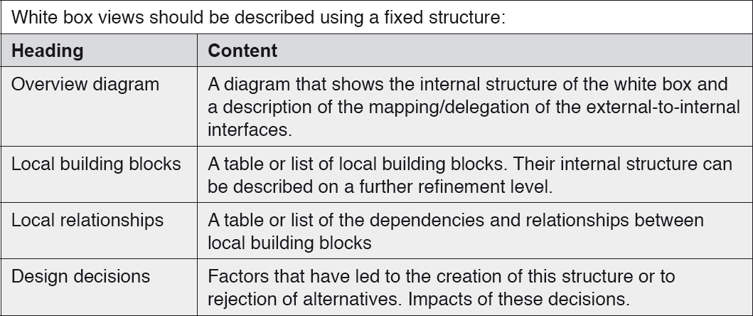
Table 4-8White box description data
For example, a white box refinement of figure 4-20 could break it down into POP3, SMTP, and SNMP building blocks, and possibly into other, self-developing building blocks.
4.4Technical/cross-cutting concepts in software architectures
The previous section presented views as the central means of describing software architectures and formulated the bases of such descriptions. Additional so-called “technical” or “cross-cutting” concepts will now be introduced in the form of brief concept descriptions (in other words, explicitly not in the form of ready-made solutions). These concepts can be important to certain architecture descriptions, but are not necessarily relevant to a specific architecture. In many cases, pre-existing concepts can be re-used in different systems.
Such technical/cross-cutting concepts cover flow control, error handling, integration, internationalization, persistence, deployment, and so on. We will begin by explaining the theory of such concepts, followed by two brief examples. These descriptions are in no way exhaustive.
4.4.1Technical/cross-cutting concepts - sample dimensions
As the name suggests, technical or cross-cutting concepts in software architectures often take effect across multiple parts (or even all) of the architecture. At the same time, several of these concepts often have to be addressed orthogonally to each other. Figure 4-21 illustrates this approach by positioning the concepts of error handling, logging, and persistence in different dimensions of a coordinate system. Error handling and logging in particular are often used in most sub-areas of a software system, but are themselves independent from one another (although logging can also be used for error logs within the scope of error handling). Persistence in common multilayer architectures (see [DE++09]) is often encapsulated in only one area, but usually includes error handling and possibly also uses logging.
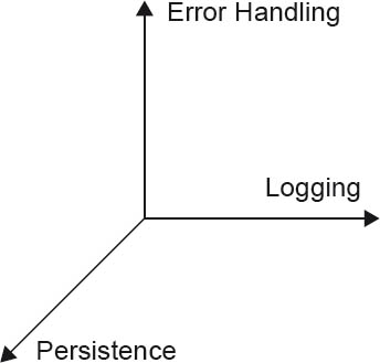
Figure 4-21Sample dimensions in a software architecture
As a further example, in database federation architectures or in heterogeneously distributed information systems (see [CKH05]), the dimensions of autonomy, heterogeneity, and distribution are typical cross-cutting concepts that need to be addressed in the associated software architectures. Similar orthogonal/cross-cutting considerations can in principle be made for all technical or cross-cutting concepts of software architectures.
4.4.2Error handling
Operational errors, partial outages and similar error cases are normal day-to-day occurrences during the use and execution of software systems. In the context of software architecture, perhaps the major task is to consider how foreseeable errors can be handled during the operation of the system. This can, for example, include intercepting formally invalid user inputs, or a “reasonable” reaction of the software to the failure of a connected database system.
Typical error handling tasks that need to be solved by the architecture and development teams include:
- Identification of error cases
- Definition of appropriate reactions to foreseeable errors, with
- Classification into categories and severity levels
- Differentiation between functional and technical errors
- Minimizing the impact of errors
- Making diagnosis of error causes easier—for example, using software system reports:
- What went wrong?
- Where did it happen?
- Why did it go wrong?
- Error prevention by the software system, for example:
- Early warning of identifiable risks
- Permitting processing tolerances
- Definition of the technologies for error handling, for example:
- C function calls return a status code.
- Java exceptions return an error description that includes the above information.
It is (also) your task as a software architect to ensure that end-to-end error handling forms part of the software system, since programs that only work in “good case” scenarios are not suitable for practical use.
4.4.3Security
Another typical cross-cutting concern in software architectures is security—a topic, where suitable cross-cutting concepts are often addressed far too late in real-life software projects.
Security is a particularly wide-ranging topic, since it more or less affects the entire software application. It begins at the user interface (for example, with the user login and protection against scripting attacks), continues through the entire code (for example, to prevent buffer overflow attacks), and extends as far as the database and its users, who should only be granted specific access rights. These are just some of the many examples that exist.
In addition to the software, organizational measures must also be taken—for example, definition of user groups and roles that have to be coordinated with administration, planning of regular security audits, involvement of employee representatives in the case of sensitive personal data, and so on.
In more general terms, a minimum set of security issues that need to be addressed are:
- Authentication
- Determination of the sender’s identity
- Authorization
- Granting of user rights based on the user’s identity
- Integrity
- Recognition of manipulation of protected data
- Confidentiality
- Transferring, transmitting, and storing data so that it can not be accessed by unauthorized parties.
- Non-repudiation
- Received messages cannot be denied by the sender.
- Availability
- Measures to counter unforeseen or deliberately caused system malfunctions.
4.5Architecture and implementation
There comes a time when you have to turn your software architecture into reality—in other words, your architecture descriptions and stepwise refinements are implemented as executable code6. Documented specifications and rules on how this mapping should take place are extremely useful. For example, specifications such as “UML component XY shall be implemented as a Java class with the appropriate interfaces”, or “We use make with the following makefiles to generate the C executable”, or “For our project we use the Java EE code structure specifications and build policies from Sun/Oracle, analogously to Duke’s bank example (with a reference)”.
Whether these specifications and rules form part of the architecture (your responsibility) or whether you work together with the development team and the rules are created there depends on how the project is organized. Particularly in large projects and organizations they often form part of the design and implementation activities and, in terms of staffing, are located there. In smaller teams this tends to be handled differently. The extent and form of rule formulations varies from project to project, but rules will always help you during the development phase and also during subsequent maintenance of your software.
As a brief example, the following section provides an excerpt from our sample CoCoME system.
4.5.1Sample implementation
The CoCoME system follows some simple implementation rules:
- Design
The CoCoME code follows a specific defined structure, to ensure that the individual software building blocks can be easily located. The CoCoME UML components are each mapped to Java packages. The interfaces provided by the components form part of the respective Java package. The Java implementation classes of these interfaces are, in each case, contained in a subpackage that is always called “impl”. The CoCoME diagrams can be mapped to this code structure accordingly. A sample of CoCoME code structure is shown in figure 4-22.
- Build
CoCoME uses Ant and an Ant build file (build.xml) to construct the entire project. Ant targets are available for translation and packaging. The result is a CoCoME.jar file.
- Run
The CoCoME.jar file can be started directly via a console using “java . . .”. The Ant build file also includes a prepared Ant target for this purpose. Some basic settings for CoCoME can be configured in the cocome.properties file—for example, the number of clients and stores. Further details on this can be found in the readme.txt file, in the code comments, and in the Javadoc-based CoCoME code documentation.
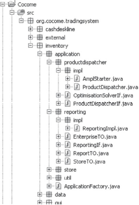
Figure 4-22Sample CoCoME Java files
4.6Common document types for software architectures
Normally a series of different documents is used to describe the architecture information covered by the previous sections. This section provides an overview of these documents.
4.6.1Central architecture description
The central architecture description is the core document for a software architecture. Where possible, it contains all information that is relevance to the architecture, such as:
- The architecture’s task, objectives (vision), quality requirements and stakeholders
- Technical and organizational conditions and constraints
- Views, decisions, and patterns used
- Technical concepts
- Quality evaluations
- Identified risks
- And so on . . .
A template document is a useful tool. For example, the document template in [ARC42] largely follows the contents described in the previous sections of this chapter.
A central architecture description can become quite large, so its description (and maintenance) in a single document may be of limited use. The contents of such a description can be managed using various tools. Some typical options are:
- Documents
Documents created using commonly available word processing software are usually easy to use and manage, as long as they don’t become too large.
- CASE/MDA/UML tools
Modeling tools with powerful report generating functionality can be extremely useful in the creation of documentation (see also Chapter 6). However, you shouldn’t underestimate the effort required for the initial project-specific configuration of such tools, particularly for small projects. The major advantage of this approach is the significantly higher level of automation during the maintenance phase (specifically, for repeat generation of architecture documentation), since UML diagrams and sections of code can be incorporated into a new document version without the need for copy and paste.
- HTML pages or wikis
“Potentially rather more pragmatic” tools such as wikis may provide a useful compromise between documentation and modeling tools.
- Any hybrid forms
A number of additional software tools for the creation of software architectures are discussed in Chapter 6.
4.6.2Architecture overview
The architecture overview serves as a brief, easy-to-read summary of the central architecture description. If possible, it should be no longer than 30 pages. It addresses similar content, but restricts itself to the essential aspects such as central views, the main quality requirements, and core decisions.
If it is not possible to create a detailed central architecture description—for example, due to the time or effort involved—the architecture overview can serve as a pared-down alternative to a complete description.
4.6.3Document overview
The document overview is a directory that serves as a per-project or per-application index of all architecture-relevant documents, and that also documents their dependencies. Organizational policies should be defined regarding the structure of this directory and where it can be found. Information should also be included on which documents should be read by whom (i.e., by which role in the project and in what order).
4.6.4Overview presentation
An overview presentation is a set of slides that presents the architecture (in technical terms) in a maximum of one hour.
A variant suitable for management should summarize the central statements and the business benefit in ten minutes.
4.6.5Architecture wallpaper
“Architecture wallpaper” is used to present a complete overview of a large number of architecture aspects. In practice, this is usually a collection of poster-sized prints detailing view representations with refinements, quality aspects, and so on. These are hung on a wall or on Metaplan boards, and allow interactive discussion of specific topics—for example, between the architecture and development teams.
Please note: “Architecture wallpaper” is an extremely useful tool for facilitating discussion, but is not the be-all and end-all. Such a large-scale depiction can have a deterrent effect on those whose task it is to implement, test, and operate the software system.
4.6.6Documentation handbook
The handbook explains the structure and function of the complete project documentation. It is also the right place for explanations of the notations used.
4.6.7Technical Information
Technical information consists of one or more documents containing important information for project developers and testers. It should be used to store information on development methods and programming guidelines, and on the building, starting, and testing of the system (see also Section 4.5).
4.6.8Documentation of external interfaces
Special attention should be given to the documentation of externally visible interfaces. These are of central importance to the interaction of the overall system with its context.
Unfortunately, in real-world projects, external interfaces often become time-consuming problem areas. Always give them plenty of attention at an early stage in the project, where you can more easily adjust individual details. It pays to devote more energy to interface documentation at an early stage than to creating really nice diagrams or adding the final grain of syntactical UML refinement in a view description.
4.6.9Template
With interface descriptions, too, it is useful to follow a consistent pattern. The table below lists a number of typical elements of interface descriptions:
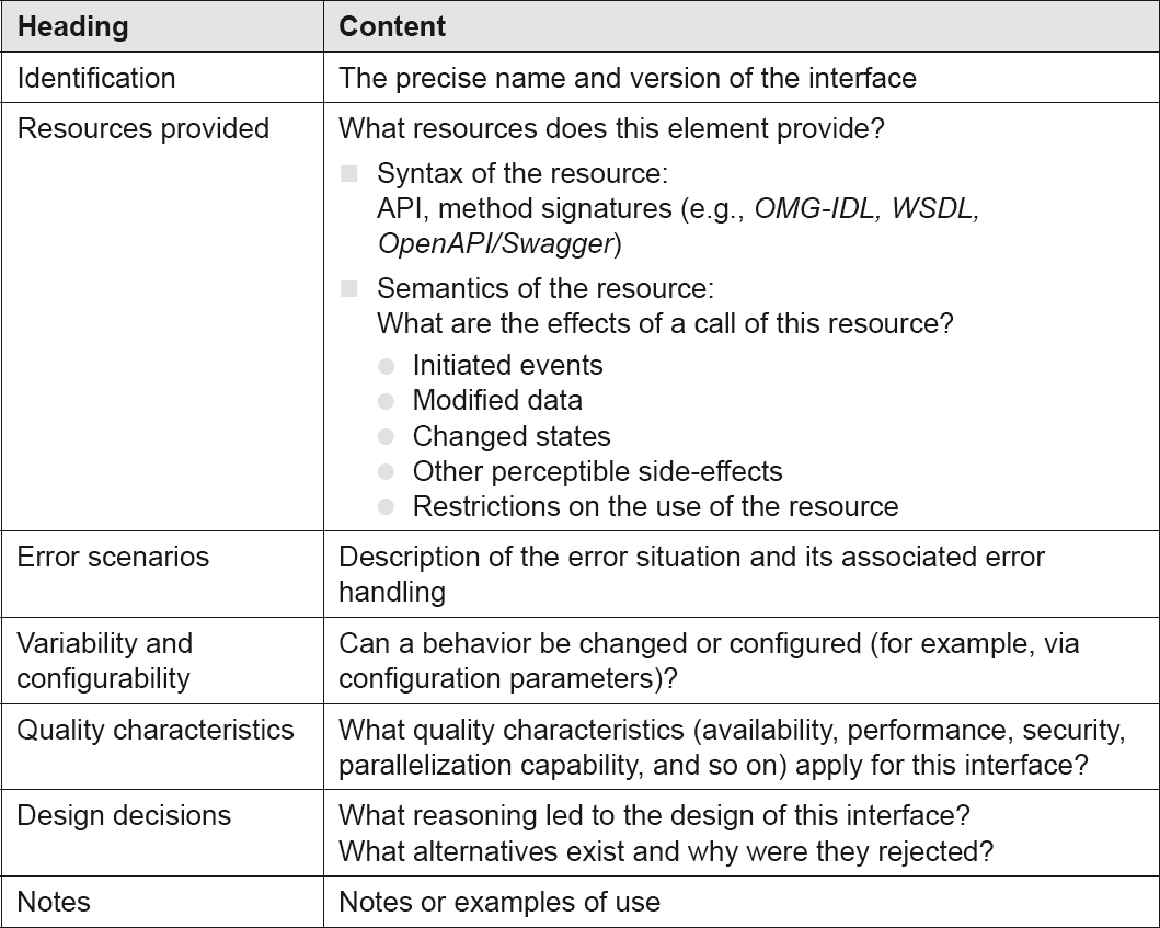
Table 4-9Typical interface description elements
4.7Best-practice rules for documentation
As is also the case with many other procedurally or technically oriented documents, a number of proven rules apply to all types of architecture documentation. These serve primarily to ensure the readability and appropriateness of such documentation.
4.7.1Rule 1: Write from the readers’ perspective
If you don’t write your documentation from the readers’ perspective, they will feel their needs have not been taken seriously. By their very nature, documents are more often read than written.
Try to avoid excessive use of technical jargon (in practice, this is always a balancing act). Particularly important specialist terminology should be explained separately—for example, in a glossary.
You should pay attention to the structure of documents and bring your thoughts and ideas into a constructive sequence. Once again, we recommend the use of appropriate document templates.
4.7.2Rule 2: Avoid unnecessary repetition
If repetitions are genuinely necessary, use them sparingly and only if they:
- Simplify the use of the documentation
- Significantly simplify its maintenance and updating
When repetitions with only minor variations occur, ask yourself the following questions:
- Is the variation intentional?
- Should importance be attached to this variation?
Note that documentation from different perspectives should not be regarded as repetition, as it serves to deepen the understanding of whatever is being documented.
4.7.3Rule 3: Avoid ambiguity
Architecture documentation often leaves future design decisions open (planned freedom of action). However, excessive freedom of interpretation in architecture specifications can easily lead to unforeseen ambiguity.
The use of formal description languages can help to overcome this. These are still (too) rarely used in practice.
If symbolic notations (such as UML) are used, you should explain the meaning of the symbols or include a reference to a separate explanatory source.
4.7.4Rule 4: Standardized organizational structure or templates
A (standardized) structure is important, particularly when you frequently create architecture documents. It provides recognition value for your readers and simplifies referencing (for example, “See the building block view in the customer management system”).
Once the structure has been defined, it should be explained to the user. A predefined structure also assists in maintaining an overview of complete and incomplete elements of the documentation. It also supports documentation quality, since all aspects to be covered by the documents are defined in advance.
4.7.5Rule 5: Justify important decisions in writing
To support your readers in comprehending your architectures and designs, it is helpful to (briefly) justify important decisions. Justifications can, for example, be provided via references to relevant company policies—for example: “For applications of type X, preference is to be given to the use of .NET or Java EE” or “The customer master data are to be stored exclusively in the central customer database on the mainframe”.
Explicitly rejected alternatives can also be of interest, as well as the advantages and disadvantages of a solution. For example, “Use of persistence frameworks developed in-house can result in increased flexibility, but compared with existing frameworks (such as Y) does not justify the associated development and long-term maintenance effort.”
Among other things, this can save time in discussions, especially if decisions have to be reconsidered under new circumstances. Justifications help your readers to understand your decisions and why they were made.
4.7.6Rule 6: Check the documentation’s suitability for use
A significant aspect of documentation is its practical, real-world use for your readership. Before you finally release documentation, you should have reviews carried out by suitable representatives of your target group and incorporate the results of these reviews into the documentation. Only the intended group of users can decide whether the right information is provided in the right way.
The review process itself should also be examined. You need to install an improvement process that regularly checks your documentation policies for deficiencies.
4.7.7Rule 7: Uncluttered diagrams
Another useful rule (for which justifiable deviations can be made) is to avoid excessively large diagrams. According to cognitive science studies, people can usefully handle between five and nine (7 ± 2) elements in diagrams.
Please note: The “architecture wallpaper” approach described in Section 4.6.5 is a clear exception to this rule.
4.7.8Rule 8: Regular updates
Introduce a process that updates your documentation regularly during development and maintenance work.
Inadequate updating
- Leads to incomplete documentation
- Reduces the benefits and the level of use of the documentation
- Prevents documentation from becoming established as an important source of information, and results in unnecessary enquiries
Unanswered questions demand timely updating. If, however, design decisions change very quickly, you shouldn’t update too often; otherwise, you’ll soon be doing nothing else. Wait until the dust has settled before you make an update. It is useful to define fixed synchronization deadlines for updates.
4.8Examples of alternative architecture frameworks
In addition to the comprehensive ISO/IEC/IEEE 42010: 2011 standard referred to in Chapter 2 and the iSAQB approach described in the previous sections, there are many alternative approaches to describing software architectures and architecture frameworks. To help you gain an impression of these (and perhaps spark your interest for further research) this section looks briefly at some examples.
Some broadly used framework approaches for software architecture, or more extensive approaches for enterprise architecture include:
- 4+1 (Kruchten)
- (US) Department of Defense Architectural Framework (DoDAF)
- Model-Driven Architecture from the Object Management Group (OMG-MDA)
- RM-ODP (Reference Model of Open Distributed Processing, ISO/IEC/ITU-T)
- Standards and Architectures for e-Government Applications (SAGA) as a framework for the German Federal Government
- SAP’s Enterprise Architecture Framework
- The Open Group Architecture Framework (TOGAF®)
- The Zachman Framework (IBM).
The following sections introduce three of these.
4.8.1The 4+1 framework
The 4+1 framework from Kruchten [Kru95] is a frequently quoted framework for describing software architectures using views. The iSAQB and arc42 approaches are based on similar concepts.
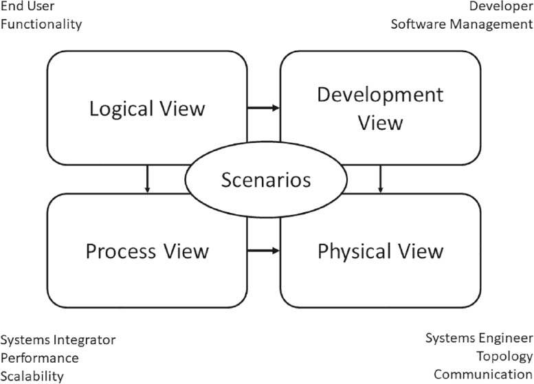
Figure 4-23The 4+1 framework (see [Kru95])
In the 4+1 framework, a differentiation is made between the logical view, the development view, the process view, and the physical view, all of which are positioned around application scenarios (see figure 4-23). The individual views address different stakeholders as follows:
- The logical view considers the software system from a functional perspective—for example, in the form of top-level class diagrams.
- The development view addresses the system from the development perspective—for example, using UML component diagrams.
- The process view is similar to the iSAQB runtime view.
- The physical view addresses mapping of the software system to specific technical systems (as in the deployment or infrastructure view).
4.8.2RM-ODP
The Reference Model of Open Distributed Processing (RM-ODP, also: ITU-T Rec. X.901-X.904 and ISO/IEC 10746) [RM-ODP] is an established, standardized reference model, used in particular for describing distributed software systems. It uses fundamental concepts developed within the scope of the Advanced Networked Systems Architecture (ANSA) project.
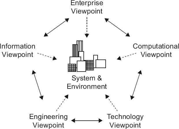
Figure 4-24RM-ODP viewpoints (see [RM-ODP])
Among other things, RM-ODP includes:
- An object modeling approach for the specification of (software) systems
- A view approach
- A definition of infrastructure for distributed software applications
RM-ODP contains the viewpoints illustrated in figure 4-24:
- Enterprise viewpoint
This viewpoint shows the operational purpose, scope of use, and rules for a software system.
- Information viewpoint
The contents and significance of the data to be processed by the software system are defined here—in other words, the information viewpoint contains a data model.
- Computational viewpoint
This viewpoint views the software system in the form of functional elements and their interfaces, broken down into objects.
- Engineering viewpoint
The engineering viewpoint addresses mechanisms and functions for distributed interaction of the system’s objects.
- Technology viewpoint
The mapping, deployment, and interconnection of software system artifacts to and with physical resources are shown here.
4.8.3SAGA
An example for a governmental approach is SAGA (Standards and Architectures for e-Government Applications) [SAGA08], which was developed under the auspices of the German Federal Ministry of the Interior (BMI). SAGA primarily pursues objectives such as interoperability, reduction of risk costs, openness, scalability, and reuse of applications in an e-government environment. As a German federal government standard, SAGA orientation is a frequent demand in public invitations to tender in Germany.
SAGA includes recommendations for software architectures, and is thus oriented to RM-ODP in this respect. It also includes methods for data and process modeling, and technical requirements (for example, for a secure infrastructure) standards and technologies (for example, for data description such as XML and XSD), middleware technologies (such as Java EE and .NET), and much more besides.
4.9Test your knowledge
Here are some detailed excerpts from the Description and communication of software architectures section of the iSAQB curriculum [isaqb-curriculum] to help you consolidate what you have learned.
 LG3-1:Explain and consider quality attributes of technical documentation.
- Ability to explain the essential fundamentals and quality characteristics of technical documentation
 LG3-2:Describe and communicate software architectures.
- The description of software architectures places special demands due to the different groups of readers (management, developers, QA, and other software architects), and different authors (software architects, developers, and possibly others).
- Awareness of the benefits of template and model-based documentation
 LG3-3:Understand how to explain and apply notations/models to describe software architecture.
- Knowledge of and ability to use selected UML diagrams that are useful for the notation of architecture views
- Knowledge of alternatives to UML diagrams (for example, flow diagrams, numbered lists, BPMN)
 LG3-4:Explain and use architectural views.
- Explain the definition of important architecture views and their importance
- Ability to document different architecture views, such as the building block view, structural view, and so on
 LG3-5:Explain and use the system context.
- Ability to differentiate between the functional and the technical context
 LG3-6:Document and communicate cross-cutting architectural concepts.
- Ability to explain the significance of cross-cutting technical concepts and architectural concepts, and to name some typical concepts
- Knowing that concepts for cross-cutting aspects can be re-used in different systems
 LG3-7:Describe interfaces.
- Ability to create interface descriptions and specifications
- Ability to differentiate between internal and external interfaces
 LG3-8:Explain and document architectural decisions.
- Ability to document and justify the systematic derivation of architecture decisions
 LG3-9:Understand the use of documentation as written communication.
- The tools used for the description of software architectures also support their design and development.
- The language and means of expression of technical documentation should be aligned to the abilities and objectives of the readers.
 LG3-10:Knowledge of additional resources and tools for documentation.
- Awareness of the fundamental features of several published frameworks for the description of software architectures—for example, 4+1, TOGAF®, ISO/IEEE-42010 (formerly 1471), arc42, and so on.
- Familiarity with ideas and examples of checklists for software architectures (see also Chapter 5)
- Familiarity with tools for the creation and maintenance of architecture documentation (see also Chapter 6)
 LG3-1:Explain and consider quality attributes of technical documentation
 LG3-2:Describe and communicate software architectures
 LG3-3:Understand how to explain and apply notations/models that describe software architecture
 LG3-4:Explain and use architectural views
 LG3-5:Explain and use the system context
 LG3-6:Document and communicate cross-cutting architectural concepts
 LG3-7:Describe interfaces
 LG3-8:Explain and document architectural decisions
 LG3-9:Understand the use of documentation as written communication
 LG3-10:Know additional resources and documentation tools


