5
Coupling Between Shear Strength and Volume Changes: Generalized 3D Stress–Dilatancy Relations
5.1. Framework of the analysis
This chapter develops the exploration of the key properties of shear strength through the macroscopic dissipation relation, which is shown to provide finely intricate relationships between friction, shear strength, and volume changes, relationships which are typical of granular media behavior.
This coupling between shear strength and volume changes has been known qualitatively for a long time: Reynolds [REY 85] named “dilatancy” the phenomenon of volume increase under shear development, and Rowe [ROW 62, ROW 69] developed the first stress–dilatancy theory; restricted to axisymmetric stresses, but matching the experimental data fairly well.
The developments presented in this chapter propose a broader approach to the subject resulting from the tensor structures induced by contact friction.
After setting the definition of a full 3D generalized “dilatancy rate,” it is shown that the macroscopic dissipation equation results in generalized 3D stress–dilatancy relationships for the allowed relevant strain modes near minimum dissipation. In specific situations of axisymmetric stresses or plane strain, it is shown that these generalized 3D stress–dilatancy relationships simplify into Rowe’s classical stress– dilatancy relations.
This chapter continues with the analysis of peak shear strength, where it is shown that the least shear strength criterion is the pyramid of the 3D Coulomb criterion (coinciding mostly with least energy dissipation solutions), but here enlarged by the peak dilatancy rate. The consequences of small deviations from the minimal solution are also analyzed: the resulting failure criterion, a kind of smoothed Coulomb criterion pyramid, displays a shape not far from the shapes of experimental failure criteria measured in the past in extensive 3D testing.
Then, the incidence of motion reversals on volume change rates is analyzed, leading to a “reversal dilatancy relation,” with coupling volume change rates just before and after a motion reversal.
Section 5.2 focuses on the 3D characteristic state, a key subject in civil engineering, as it is directly related to liquefaction. First, it reminds us that the macroscopic dissipation equation near isotropic stress states simplifies into a volume contraction relation, stating that any motion will imply volume contraction. As volume contraction during motion is a key to the susceptibility of saturated granular media to liquefaction, this inter-relation between friction, volume changes, and stress states deserves an analysis of practical interest, that is, the eventuality of a definite limit between stress states and motions inducing volume contractions and those inducing dilatancy.
This limit, named the “characteristic state” after Luong [LUO 78], is investigated for each of the six allowed strain modes near minimum dissipation, showing that:
- – A characteristic state does exist, coinciding with the critical state Coulomb failure criterion.
- – It constitutes a definite transition between contractive motions and dilatant motions for certain strain modes, but not for all, as the dissipation equation does not allow all strain modes to undergo dilatancy.
The section ends with a summary of the main characteristics of the six allowed strain modes, with regard to volume changes, and motion sustainability toward the critical state.
This chapter ends with a remarkable link with fluid mechanics when friction vanishes, as the “perfect incompressible fluid” behavior, a basis of hydraulics, emerges as a prominent solution of the macroscopic dissipation equation when friction vanishes.
5.2. Definition of a general 3D dilatancy rate
For the sake of simplicity, the assumption of coaxiality (simple coaxiality, not ordered) is maintained in the following. As these properties result from an intrinsically irreversible dissipative process, they should be considered as dependent to some extent on boundary conditions, as discussed in Chapter 4.
Far from the critical state, the development of shear strength with straining is associated with volume changes and especially with dilatancy. Thus, along a monotonic strain path starting from a given initial state toward the asymptotic critical state, volume changes appear as a kind of transient regime within the material in motion. Along with this motion, the dissipation equation [1.30] sets a relationship between these volume changes and the stress state. A simple example of this relation occurs near isotropic stresses condition, as the dissipation equation reduces to a “volume contraction relation,” easily derived by inserting an isotropic stress inside the dissipation equation
From this, the “volume contraction relation” (recalling that under our conventions of sign,  denotes a contraction in volume), any movement near the isotropic stress state will induce a volume contraction whose intensity is proportional to the apparent friction factor
  The physical reason for this contraction in motion under isotropic stresses is quite simple: the material must get the mechanical energy for the dissipation in its movement from the outside, and under isotropic stresses, the only movements that allow a gain in mechanical energy from external forces are precisely those with volume contraction.
In more general stress conditions, the approach of variable specific volume motion will be similar to the previous approach for failure criterion at the critical state (Chapter 4), but here it is taken into account for volume change rate, instead of for the stationary specific volume condition (equation [4.1]). For general 3D strain regimes, the definition of a kind of “generalized dilatancy rate” d, which should be a complete symmetric formulation with principal strain rates, should be consistent as much as possible with classical definitions of “dilatancy rate” in the reference situations of axisymmetric stresses or plane strain.
The selected definition for general situations is as follows:
With this definition (and our conventions of sign), d > 0 when there is a movement, d > 1 denotes motion with dilatancy, and d < 1 denotes motion with volume contraction. The analytical expression of d is generally motion-dependent, as it depends on the strain rate signature. However the motions under isotropic stresses, ruled by equation [5.1], must satisfy:
For each of the six strain modes allowed by the dissipation equation [1.30] as defined in Table 1.2, the above definition results in simple basic inequalities linking principal stress ratios and the dilatancy rate, which is a consequence of the dissipation relation, as shown in Appendix A.5.1. These basic inequalities, which transform into simple equalities under specific conditions, are listed in Table 5.1 (we note S for  ).
).
As σ1 ≥ σ2 ≥ σ3 > 0, the table draws specific key characteristics of these strain modes, with regard to their volumetric behavior, as follows:
- – Modes I and II Direct, and also I and II Transverse, are compatible with either contraction or dilatancy according to the stress state (as corresponding inequalities are compatible with either d < 1 or d > 1).
- – Modes I and II Reverse are only compatible with strong volume contractions (as corresponding inequalities mean
 , with the typical value S = 0.5, we obtain d ≤ 0.33).
 - – When certain required specific conditions are met, these inequalities transform into equalities, which are simple relationships between principal stress ratios and the dilatancy rate, multiplied by a material factor resulting from apparent friction: these are the classical stress–dilatancy relationships found by Rowe, although under far more restricted conditions; this point will be developed in the following sections.
- – Note from Table 5.1 that for general true 3D strain motion, these simple stress–dilatancy relationships can occur only for Modes I and II Direct or Reverse (not for Transverse, as stress isotropy is required) under axisymmetric stresses conditions, that is b = 0 or b = 1.
- – Each of these general 3D strain motions includes two plane strain motions within its borders, e.g. Mode I Direct (+,−,−) includes at its borders both plane strain motions (+,0,−) and (+,−,0), for which the inequality always transforms into equality, as one dimension disappears inside the dissipation equation.
Table 5.1. Basic dilatancy relations for the six allowed strain modes

These characteristics, which are the direct consequences of the macroscopic dissipation equation, will reappear in the following sections.
5.3. Generalized stress–dilatancy relationships for relevant strain modes
The analysis of generalized stress–dilatancy relationships is now focused on the four relevant strain Modes I and II Direct and Transverse, as the strain Modes I and II Reverse are only compatible with strong volume contractions; the analytical problem is treated in Appendix A.5.2.
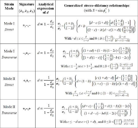
For each of these strain modes, the dissipation relation forms an analytical relationship between the principal stress ratio σ1 / σ3, the deviatoric parameters of stress and strain rates b and c, and the generalized dilatancy rate d. These analytical relations are homographic functions of parameters b, c, and d, differing from one strain mode to the other, because of the differences in strain rate signatures. These relations constitute the generalized three-dimensional stress–dilatancy relationships for each of the four strain modes considered, summarized in the following Table 5.2, together with their conditions of validity:
Table 5.2. Generalized stress–dilatancy relationships resulting from the dissipation equation
5.4. Simplification into Rowe’s relations for particular conditions
As noted above, these generalized stress–dilatancy relationships simplify greatly in specific situations:
- – in the neighborhood of isotropic stress states
 ;
; - – under axisymmetric stress states, Mode I Direct with b = 0, or Mode II Direct with b = 1;
- – under plane strain (
 = 0, with c = d / (1 + d)) in Modes I and II Direct.
Under these simplifying situations, these generalized relations (Table 5.2) reduce explicitly to the classical Rowe stress–dilatancy relationship
This stress–dilatancy relationship binds the development of shear resistance to the volume changes, and under monotonic deformation (as practiced in common laboratory tests), the maximum shear strength will correspond to the maximum dilatancy rate observed during motion.
The physical reason for this relation is quite simple in our dissipative approach:
- – with dilatancy, the material expanding against external stresses must produce additional output mechanical work during this expansion;
- – this additional output work rate shall be fed by more input work rate: the material demands more energy to be deformed, hence opposes more “resistance”;
- – as the ratio input power/output power remains the same near minimal dissipation, the stress–dilatancy relationships are merely the expression of this linear power balance with the incidence of volume change.
These Rowe stress–dilatancy relationships, quite convincing experimentally, remain among the most highly quoted key characteristics of granular media behavior ([BAR 66, ROW 69, ODA 75, FRO 79, 86, 12, CAM 85, 12, HAN 01], and many others); examples of experimental verification are given in Chapter 6.
In fact, as observed in Table 5.1, our dissipative approach states that all the strain modes present, in certain conditions, such a simplification; however, these Modes I and II Direct and related plane strain ( = 0) mentioned above are the only ones for which the stress ratio is the ratio between the major (σ1) and the minor (σ3) principal stress. For all other cases:
- – in Modes I and II Reverse, the stress ratio involved is σ3 / σ1 instead of σ1 / σ3, because in these Reverse modes, the eigendirections bearing “input power” and “output power” are reverted in comparison with the corresponding Direct Modes;
- – in Modes I and II Transverse, the stress ratio is between the intermediate principal stress σ2 together with either the major or the minor principal stress, because in the corresponding dissipation relation, one of the “input power” or “output power” is borne by that intermediate eigendirection no. 2.
5.5. Failure criterion at peak strength with dilation
For the above simplifying situations, stress–dilatancy relationships set that the peak shear strength, i.e. the maximum ratio of σ1 /σ3, corresponds explicitly to the Coulomb criterion (at critical state), enlarged by maximum dilatancy rate dmax. In more general situations, analysis of generalized stress-dilatancy relationships (see Appendix A.5.2), sets that:
- – the peak least shear strength criterion, in general, will also correspond to the Coulomb criterion (at critical state) enlarged by the peak dilatancy rate (dMax)
- – if deviation from that minimal solution remains when peak resistance is reached, then the peak strength criterion is generally exterior to the Coulomb criterion enlarged by the peak dilatancy rate, and is adherent to this reference surface, either at axisymmetric stresses or at plane strain conditions.
5.5.1. The least shear strength criterion: the Coulomb failure criterion
The exercise practiced in Chapter 4 has been repeated for boundary conditions A, which is most practiced in 3D testing. The results, (see Appendix A.5.2), are similar to those found previously at a critical state: a least shear strength solution also exists which, if it should be reached, is the Coulomb criterion, enlarged by the peak dilatancy rate, and the least dissipation solution is again a subset of the least shear strength solution.
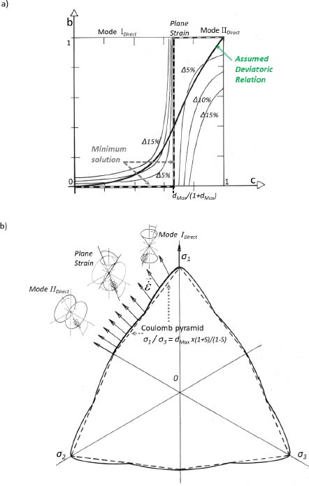
Figure 5.1. Peak shear strength failure criterion (with dilatancy dmax = 2). Incidences of moderate deviations from the minimum solution. (a) Assumed “deviatoric relation.” (b) Resulting failure criterion. For a color version of the figure, please see www.iste.co.uk/frossard/geomaterials.zip
5.5.2. Incidence of small deviations from the minimal solution
The material in monotonic motion can again be considered as following a transient trajectory converging asymptotically toward the critical state. In this author’s point of view, the “deviatoric relation” at peak shear strength should be evolving toward the minimal solution, although with more significant deviation than near the critical state, thus corresponding to a 3D failure criterion shape similar to the one shown in Figure 4.8 of Chapter 4.
A possible solution of that kind, computed in a similar way as in Chapter 4, including effects of a uniform peak dilatancy rate of 2 (corresponding to initially dense materials) and designed to secure deviations within 12% for the principal stress ratio, has been computed from the relations provided in Table 5.2 and shown in Figure 5.1. The shape is not different from the shapes of experimental failure criterions measured in previous extensive 3D testing [ART 77, LAD 73].
5.6. Incidence of strain reversals on volume change rates
After monotonic conditions, the incidence of strain reversals on volume change rates can be considered now. For simplicity, we will focus only on axisymmetric stress conditions or plane strain ( = 0) and analyze the characteristics of volume change rates around motion reversal (see Table 5.3).
For the conditions considered in Table 5.3, it can be deduced that the generalized dilatancy rates just before a motion reversal d and just after d′, under the same principal stress ratio, verify a “reversal dilatancy relation”
This relation shows that if the material is dilating before motion reversal (d > 1), then it will be strongly contracting after a reversal d′ ≪ 1, as observed usually in laboratory testing, and the stronger the dilatancy before, the stronger the contraction after. The relation [5.6] holds around isotropic stress states, for any kind of change in motion.
An outstanding experimental example of this reversal dilatancy relation is detailed in Chapter 6 (section 6.3), resulting from an analysis of large amplitude cyclical solicitation data in a true 3D apparatus.
Table 5.3. Characteristics of volume change around motion reversal, under axisymmetric stress conditions or plane strain ( = 0)
= 0)
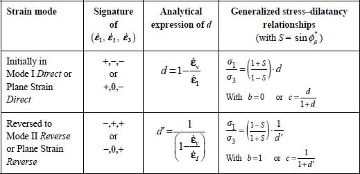
The relations given in Table 5.3 also indicate the following conditions that take place after a motion reversal in these simple conditions:
- – the behavior predicted by the dissipation equation is that the material will “jump” from one strain mode to another;
- – the ratio of principal stresses will remain bound to the dilatancy rate through a linear relation, but different from the linear relation prevailing before the strain reversal.
This kind of behavior has been repeatedly observed in physical experiments [BAR 66], some of them discussed in Chapter 6, and in numerical simulations by elaborate discrete element methods with realistic particles (see [NOU 03]). The experimental example detailed in Chapter 6, resulting from the analysis of large amplitude cyclical solicitation data in a true 3D apparatus, provides another illustration of the above conditions.
For more general transitions between two of the six allowed strain modes (Table 5.1) through imposed reversal of one or various strain rates, the present dissipative approach still predicts that the material will “jump” from one strain mode to another; however, the relations between volume changes rates before and after this transition will not be so simple as in the particular situations mentioned above.
5.7. 3D Characteristic state
5.7.1. Framework of the analysis
The above relations show that shear strength in the material in motion may vary strongly between peak strength and critical state, due to volume changes. The factor between the principal stress ratio at peak shear strength and the same ratio at critical state shear strength is the peak dilatancy rate, which may reach values up to 2.2 or more (see [FRO 79, CHA 80]). This difference between peak and critical state shear strengths outlines the key role played by volume changes in relation to the stress states, whereas this inter-relation is embedded inside the dissipation relation.
On the contrary, near the isotropic stress condition, we have seen that the same dissipation relation reduces to a “volume contraction relation” (equation [5.1]). This volume contraction near isotropic stresses is well known in laboratories as it appears systematically at the beginning of any classical “triaxial test” on granular material. It appears as a direct effect of energy dissipation by friction; as the material in motion must get from the outside the mechanical energy required to feed the dissipation, it gets this mechanical energy by the only way possible under isotropic stresses, i.e. by absorbing mechanical work from external pressure through volume contraction.
Volume contraction during motion also increases the susceptibility to liquefaction for saturated granular media. Hence, this inter-relation between friction, volume changes, and stress states raises a question of practical interest: is there a definite limit between stress states and motions inducing volume contraction, and those inducing dilatancy?
This limit, named the “characteristic state” [LUO 78], can be investigated for all the six strain modes listed in Table 5.1, and as detailed in Appendix A.5.3. For each of these strain modes, the dissipation equation allows us to set both necessary conditions and sufficient conditions to achieve volume contraction (and similarly for dilatancy).
5.7.2. Key results
The key results of this analysis (see Figure 5.2) are as follows:
- – A characteristic state exists in the present approach; it coincides in the principal stress referential with the pyramid of the critical state Coulomb criterion.
- – Any motion under stress states inside the characteristic state will generate volume contraction.
- – For both Modes I and II Direct, this limit is also the limit of dilatant motions, so crossing the characteristic state limit will be, for these modes, a transition between volume contraction motion inside and dilatant motion outside, i.e. a minimum in the variation of specific volume.
- – However, it is not the case for all strain modes, as Modes I and II Reverse do not allow for any dilatancy because of energy dissipation.
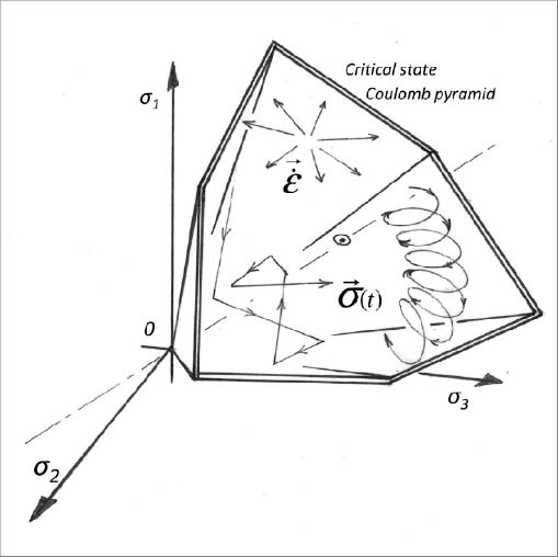
Figure 5.2. Characteristic state: any motion associated with a stress-path remaining inside the pyramid generates a contraction of specific volume
5.8. Nature of the six allowed strain modes regarding volume changes and motion sustainability
In Chapter 4, proof has been given that, at the critical state, the “minimum dissipation rule” allows the analyzed strain modes to tend toward strain regimes securing the ordered coaxiality among all allowed simple coaxial solutions, where this is also verified in the case of Modes I and II Transverse (for the minimal solution)
The peak shear strength criterion shown in section 5.5 displays the same property.
Thus, starting from a given state of stress, if a motion is set reversing the order of coaxiality (e.g. Modes I and II Reverse, or Modes I and II Transverse), the material in motion will evolve toward the restoration of ordered coaxiality.
For example:
- – Under plane strain conditions (
 ), if motion is set with
  (extension) and
  (contraction), the ratio σ1 / σ3 decreases with motion until reversing the order of principal stresses (i.e. the principal direction that is initially no. 1 becomes the direction of minor principal stress, and reciprocally for the principal direction that is initially no. 3), and this new situation restores the ordered coaxiality.
 - – Similarly, under axisymmetric stresses conditions, specific characteristics of the six strain modes, resulting from the analysis in Appendices A.5.2 and A.5.3, are summarized in Table 5.4.
Thus, only Modes I and II Direct can be considered as potentially able to withstand large strains under monotonic motion, converging toward the critical state. The other four strain modes that cannot withstand the critical state (Modes I and II Reverse, see Appendix A.5.2), or only under restrictive constraints (Modes I and II Transverse), are considered as transient strain regimes under which the material evolves toward the restoration of the ordered coaxiality under one of Modes I or II Direct, or plane strain.
The experimental example detailed in Chapter 6, resulting from the analysis of large amplitude cyclical solicitation data in a true 3D apparatus, provides an illustration of the above-mentioned evolution.
Table 5.4. The six strain mode characteristics, regarding volume changes and critical state motion
| Strain mode | Signature of  |
Volume contraction | Dilatancy | Large strains at a critical state |
| Mode I Direct | +,−,− | Allowed | Allowed | Allowed Sustainable at a critical state |
| Mode I Transverse | −,+,− | Allowed | Restricted | Possible but with strong restrictions |
| Mode I Reverse | −,−,+ | Allowed | Not allowed | Not allowed |
| Mode II Direct | +,+,− | Allowed | Allowed | Allowed Sustainable at a critical state |
| Mode II Transverse | +,−,+ | Allowed | Restricted | Possible but with strong restrictions |
| Mode II Reverse | −,+,+ | Allowed | Not allowed | Not allowed |
5.9. A direct link with fluid mechanics
From the results of Chapter 4, when the apparent inter-granular friction  (i.e. coefficient
  ) tends toward zero, the Coulomb failure criterion (critical state) reduces to the axis of isotropic stress; as the shear resistance tends toward zero, the material can undergo large strains at constant volume under isotropic stresses.
More widely, it may be observed [FRO 12a] that when this apparent inter-granular friction tends toward zero, a remarkable analytic solution arises in the dissipation equation [1.30] for this behavior under slow motion, displaying the following characteristics irrespective of the motion amplitude in our equivalent pseudo-continuum:
- – there is no more dissipation;
- – allowable states of stresses remain isotropic;
- – the specific volume remains constant (this characteristic is consistent with the fact that any significant dilatancy is likely to become unstable at the mesoscopic scale in the absence of friction);
- – the coaxiality matter also vanishes as the stress states become isotropic, and micro-polarization characteristics vanish as the norm N disappears from the key equations.
These characteristics correspond to the mechanical behavior known as the “perfect incompressible fluid,” the basis of hydraulics.
This result appears physically rational, as the granular medium in slow motion becomes a mass of grains sliding without friction against each other at random while staying in contact; it is the classical microscopic description of a liquid.
5.10. Conclusions
Thus, beyond the Coulomb failure criterion, the same macroscopic dissipative structure due to friction, condensed into dissipation relation (equation [1.30]), also sets those behavior characteristics typically of granular media, close coupling friction, shear strength, and volume changes. This same dissipative structure also allows, among all allowable simply coaxial solutions, the motion to evolve toward ordered coaxiality.
At this stage, an abstract of the global characteristics of macroscopic mechanical behavior resulting from the coupling between shear strength and volume changes (itself a consequence of the dissipative structure induced by contact friction) is shown in Figure 5.3, which may be observed in current experimental tests, e.g. the classical “triaxial” test. Other global characteristics related to other kinds of experimental tests are detailed in the experimental validations described in Chapter 6. These macroscopic characteristics are naturally associated with the micro-scale polarization patterns of the sliding motions of elementary contacts through the present dissipative approach (see Figure 5.3).
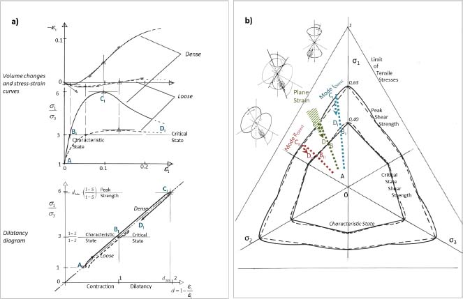
Figure 5.3. Precis of global characteristics resulting from the dissipation relation, regarding coupling between shear strength and volume changes. (a) Features on stress–strain curves and volume changes for Mode I (b = 0): coupling between shear strength and volume changes in the dilatancy diagram. (b) Features on an octahedral stress plane: shear strength criteria and b = cst. Stress-paths. For a color version of the figure, please see www.iste.co.uk/frossard/geomaterials.zip


