
MATHEMATICAL FOUNDATIONS
3.7Eye Space and the Synthetic Camera
3.10GLSL Functions for Building Matrix Transforms

Computer graphics makes heavy use of mathematics, particularly matrices and matrix algebra. Although we tend to consider 3D graphics programming to be among the most contemporary of technical fields (and in many respects it is), many of the techniques that are used actually date back hundreds of years. Some of them were first understood and codified by the great philosophers of the Renaissance era.
Virtually every facet of 3D graphics, every effect—movement, scale, perspective, texturing, lighting, shadows, and so on—will be accomplished largely mathematically. Therefore, this chapter lays the groundwork upon which every subsequent chapter relies.
It is assumed the reader has a basic knowledge of matrix operations; a full coverage of basic matrix algebra is beyond the scope of this text. Therefore, if at any point a particular matrix operation is unfamiliar, it may be necessary to do some supplementary background reading to ensure full understanding before proceeding.
3D space is generally represented with three axes: X, Y, and Z. The three axes can be arranged into two configurations, right-handed or left-handed. (The name derives from the orientation of the axes as if constructed by pointing the thumb and first two fingers of the right versus the left hand, at right angles.)

Figure 3.1
3D coordinate systems.
It is important to know which coordinate system your graphics programming environment uses. For example, the majority of coordinate systems in OpenGL are right-handed, whereas in Direct3D the majority are left-handed. Throughout this book, we will assume a right-handed configuration unless otherwise stated.
3.2POINTS
Points in 3D space can be specified by listing the X, Y, Z values, using a notation such as (2, 8, -3). However, it turns out to be much more useful to specify points using homogeneous notation, a representation first described in the early 1800s. Points in homogeneous notation contain four values. The first three correspond to X, Y, and Z, and the fourth, W, is always a fixed nonzero value, usually 1. Thus, we represent this point as (2, 8, -3, 1). As we will see shortly, homogeneous notation will make many of our graphics computations more efficient.
The appropriate GLSL data type for storing points in homogeneous 3D notation is vec4 (“vec” refers to vector, but it can also be used for a point). The GLM library includes classes appropriate for creating and storing 3-element and 4-element (homogeneous) points in the C++/OpenGL application, called vec3 and vec4 respectively.
A matrix is a rectangular array of values, and its elements are typically accessed by means of subscripts. The first subscript refers to the row number, and the second subscript refers to the column number, with the subscripts starting at 0. Most of the matrices that we will use for 3D graphics computations are of size 4x4, as shown in Figure 3.2:

Figure 3.2
4x4 matrix.
The GLSL language includes a data type called mat4 that can be used for storing 4x4 matrices. Similarly, GLM includes a class called mat4 for instantiating and storing 4x4 matrices.
The identity matrix contains all zeros, with ones along the diagonal:

Any item multiplied by the identity matrix is unchanged. In GLM, the constructor call glm::mat4 m(1.0f) builds the identity matrix in the variable m.
The transpose of a matrix is computed by interchanging its rows and columns. For example:

The GLM library and GLSL both have transpose functions: glm::transpose(mat4) and transpose(mat4) respectively.
Matrix addition is straightforward:

In GLSL the + operator is overloaded on mat4 to support matrix addition.
There are various multiplication operations that can be done with matrices that are useful in 3D graphics. Matrix multiplication in general can be done either left to right or right to left (note that since these operations are different, it follows that matrix multiplication is not commutative). Most of the time we will use right-to-left multiplication.
In 3D graphics, multiplying a point by a matrix is in most cases done right to left, and produces a point, as follows:

Note that we represent the point (X,Y,Z) in homogeneous notation as a 1-column matrix.
GLSL and GLM both support multiplying a point (a vec4, to be exact) by a matrix with the * operator.
Multiplying a 4x4 Matrix by another 4x4 matrix is done as follows:
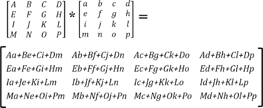
Matrix multiplication is frequently referred to as concatenation, because as will be seen, it is used to combine a set of matrix transforms into a single matrix. This ability to combine matrix transforms is made possible because of the associative property of matrix multiplication. Consider the following sequence of operations:
New Point = Matrix1 * (Matrix2 * (Matrix3 * Point))
Here, we multiply a point by Matrix3, then multiply that result by Matrix2, and that result finally by Matrix1. The result is a new point. The associative property ensures that the previous computation is equivalent to:
New Point = (Matrix1 * Matrix2 * Matrix3) * Point
Here, we first multiply the three matrices together, forming the concatenation of Matrix1, Matrix2, and Matrix3 (which itself is also a 4x4 matrix). If we refer to this concatenation as MatrixC, we can rewrite the previous operation as:
New Point = MatrixC * Point
The advantage here, as we will see in Chapter 4, is that we will frequently need to apply the same sequence of matrix transformations to every point in our scene. By pre-computing the concatenation of all of those matrices once, it turns out that we can reduce the total number of matrix operations needed manyfold.
GLSL and GLM both support matrix multiplication with the overloaded * operator.
The inverse of a 4x4 matrix M is another 4x4 matrix, denoted M-1, that has the following property under matrix multiplication:
M*(M-1) = (M-1)*M = identity matrix
We won’t present the details of computing the inverse here. However, it is worth knowing that determining the inverse of a matrix can be computationally expensive; fortunately, we will rarely need it. In the rare instances when we do, it is available in both GLSL and GLM through the mat4.inverse() function.
3.4TRANSFORMATION MATRICES
In graphics, matrices are typically used for performing transformations on objects. For example, a matrix can be used to move a point from one location to another. In this chapter we will learn several useful transformation matrices:
•Translation
•Rotation
•Scale
•Projection
•Look-At
An important property of our transformation matrices is that they are all of size 4x4. This is made possible by our decision to use the homogeneous notation. Otherwise, some of the transforms would be of diverse and incompatible dimensions. As we have seen, ensuring they are the same size is not just for convenience; it also makes it possible to combine them arbitrarily, and pre-compute groups of transforms for improved performance.
3.4.1Translation
A translation matrix is used to move items from one location to another. It consists of an identity matrix, with the X, Y, and Z movement(s) given in locations A03, A13, A23. Figure 3.3 shows the form of a translation matrix and its effect when multiplied by a homogeneous point; the result is a new point “moved” by the translate values.

Figure 3.3
Translation matrix transform.
Note that point (X,Y,Z) is translated (or moved) to location (X+Tx, Y+Ty, Z+Tz) as a result of being multiplied by the translation matrix. Also note that multiplication is specified right to left.
For example, if we wish to move a group of points upward 5 units along the positive Y direction, we could build a translation matrix by taking an identity matrix and placing the value 5 in the Ty position. Then we simply multiply each of the points we wish to move by the matrix.
There are several functions in GLM for building translation matrices and for multiplying points by matrices. Some relevant operations are:
•glm::translate(x, y, z) builds a matrix that translates by (x,y,z)
•mat4 * vec4
3.4.2Scaling
A scale matrix is used to change the size of objects or move points toward or away from the origin. Although it may initially seem strange to scale a point, objects in OpenGL are defined by groups of points. So, scaling an object involves expanding or contracting its set of points.
The scale matrix transform consists of an identity matrix with the X, Y, and Z scale factors given in locations A00, A11, A22. Figure 3.4 shows the form of a scale matrix and its effect when multiplied by a homogeneous point; the result is a new point modified by the scale values.

Figure 3.4
Scale matrix transform.
There are several functions in GLM for building scale matrices and multiplying points by scale matrix transforms. Some relevant operations are:
•glm::scale(x,y,z) builds a matrix that scales by (x,y,z)
•mat4 * vec4
Scaling can be used to switch coordinate systems. For example, we can use scale to determine what the left-hand coordinates would be, given a set of right-hand coordinates. From Figure 3.1 we see that negating the Z coordinate would toggle between right-hand and left-hand systems, so the scale matrix transform to accomplish this is:

Rotation is a bit more complex, because rotating an item in 3D space requires specifying (a) an axis of rotation and (b) a rotation amount in degrees or radians.
In the mid-1700s, the mathematician Leonhard Euler showed that a rotation around any desired axis could be specified instead as a combination of rotations around the X, Y, and Z axes [EU76]. These three rotation angles around the respective axes have come to be known as Euler angles. The discovery, known as Euler’s Theorem, is very useful to us, because rotations around each of the three axes can be specified using matrix transforms.
The three rotation transforms, around the X, Y, and Z axes respectively, are shown in Figure 3.5. There are several functions in GLM for building and using rotation matrices as well:


Figure 3.5
Rotation transform matrices.
In practice, using Euler angles to rotate an item around an arbitrary line in 3D space takes a couple of additional steps if the line doesn’t pass through the origin. In general:
1.Translate the axis of rotation so that it goes through the origin.
2.Rotate by appropriate Euler angles around X, Y, and Z.
3.Undo the translation of Step 1.
The three rotation transforms shown in Figure 3.5 each have the interesting property that the inverse rotation happens to equal the transpose of the matrix. This can be verified by examining the previous matrices, recalling that cos(-θ) = cos(θ), and sin(-θ) = -sin(θ). This property will become useful later.
Euler angles can cause certain artifacts in some 3D graphics applications. For that reason it is often advisable to use quaternions for computing rotations. Many resources exist for those readers interested in exploring quaternions (e.g., [KU98]). Euler angles will suffice for most of our needs.
3.5VECTORS
Vectors specify a magnitude and direction. They are not bound to a specific location; a vector can be “moved” without changing what it represents.
There are various ways to notate a vector, such as a line segment with an arrowhead at one end, or as a pair (magnitude, direction), or as the difference between two points. In 3D graphics, vectors are frequently represented as a single point in space, where the vector is the distance and direction from the origin to that point. In Figure 3.6, vector V (shown in red) can be specified either as the difference between points P1 and P2, or as an equivalent distance from the origin to P3. In all of our applications, we specify V as simply (x,y,z), the same notation used to specify the point P3.

Figure 3.6
Two representations for a vector V.
It is convenient to represent a vector the same way as a point, because we can use our matrix transforms on points or vectors interchangeably. However, it also can be confusing. For this reason we sometimes will notate a vector with a small arrow above it (such as  ). Many graphics systems do not distinguish between a point and a vector at all, such as in GLSL and GLM, which provide data types vec3/vec4 that can be used to hold either points or vectors. Some systems (such as the graphicslib3D library used in an earlier Java-based edition of this book) have separate point and vector classes, and enforce appropriate use of one or the other depending on the operation being done. It is an open debate as to whether it is clearer to use one data type for both, or separate data types.
There are several vector operations that are used frequently in 3D graphics, for which there are functions available in GLM and GLSL. For example, assuming vectors A(u,v,w) and B(x,y,z):
Addition and Subtraction:
A ± B = (u ± x, v ± y, w ± z)
glm: vec3 ± vec3
GLSL: vec3 ± vec3
Normalize (change to length=1):
 = A/|A| = A/sqrt(u2+v2+w2), where |A| ≡ length of vector A
glm: normalize(vec3) or normalize(vec4)
GLSL: normalize(vec3) or normalize(vec4)
Dot Product:
A ● B = ux + vy + wz
glm: dot(vec3,vec3) or dot(vec4,vec4)
GLSL: dot(vec3,vec3) or dot(vec4,vec4)
Cross Product:
A x B = (vz-wy, wx-uz, uy-vx)
glm: cross(vec3,vec3)
GLSL: cross(vec3,vec3)
Other useful vector functions are magnitude (which is available in both GLSL and GLM as length()), and reflection and refraction (both are available in GLSL and GLM).
We shall now take a closer look at the functions dot product and cross product.
3.5.1Uses for Dot Product
Throughout this book, our programs make heavy use of the dot product. The most important and fundamental use is for finding the angle between two vectors. Consider two vectors  and
and  , and say we wish to find the angle θ separating them.
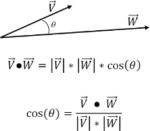
Therefore, if  and
and  are normalized (i.e., of unit length—here we use the “^” notation for normalization, as shown earlier), then:

Interestingly, we will later see that often it is cos(θ) that we need, rather than θ itself. So, both of the previous derivations will be directly useful.
The dot product also has a variety of other uses:
•Finding a vector’s magnitude: 
•Finding whether two vectors are perpendicular, if: 
•Finding whether two vectors are parallel, if: 
•Finding whether two vectors are parallel but pointing in opposite directions, if: 
•Finding whether the angle between vectors lies in the range (-90°..+90°): 
•Finding the minimum signed distance from point P=(x,y,z) to plane S=(a,b,c,d). First, find unit vector normal to S:  and shortest distance
  from the origin to the plane. Then, the minimum signed distance from P to S is:
  and the sign of this distance determines on which side of the plane S point P lies.
3.5.2Uses for Cross Product
An important property of the cross product of two vectors, which we will make heavy use of throughout this book, is that it produces a vector that is normal (perpendicular) to the plane defined by the original two vectors.
Any two non-collinear vectors define a plane. For example, consider two arbitrary vectors  and
and  . Since vectors can be moved without changing their meaning, they can be moved so that their origins coincide. Figure 3.8 shows a plane defined by
  and
and  , and the normal vector resulting from their cross product. The direction of the resulting normal obeys the right-hand rule, wherein curling the fingers of one’s right hand from
  to
to  causes the thumb to point in the direction of the normal vector
  .
.
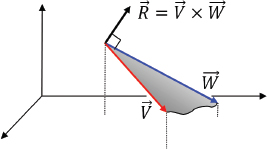
Figure 3.7
Cross product produces normal vector.
Note that the order is significant;  ×
× would produce a vector in the opposite direction from
  .
.
The ability to find normal vectors by using the cross product will become extremely useful later when we study lighting. In order to determine lighting effects, we will need to know outward normals associated with the model we are rendering. Figure 3.8 shows an example of a simple model made up of six points (vertices) and the computation employing cross product that determines the outward normal of one of its faces.
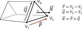
Figure 3.8
Computing outward normals.
3.6LOCAL AND WORLD SPACE
The most common use for 3D graphics (with OpenGL or any other framework) is to simulate a three-dimensional world, place objects in it, and then view that simulated world on a monitor. The objects placed in the 3D world are usually modeled as collections of triangles. Later, in Chapter 6, we will dive into modeling. But we can start looking at the overall process now.
When building a 3D model of an object, we generally orient the model in the most convenient manner for describing it. For example, when modeling a sphere, we might orient the model with the sphere’s center at the origin (0,0,0) and give it a convenient radius, such as 1. The space in which a model is defined is called its local space, or model space. OpenGL documentation uses the term object space.
The sphere might then be used as a piece of a larger model, such as becoming the head on a robot. The robot would, of course, be defined in its own local/model space. Positioning the sphere model into the robot model space can be done using the matrix transforms for scale, rotation, and translation, as illustrated in Figure 3.9. In this manner, complex models can be built hierarchically (this is developed further in Section 4.8 of Chapter 4 using a stack of matrices).
In the same manner, modeled objects are placed in a simulated world by deciding on the orientation and dimensions of that world, called world space. The matrix that positions and orients an object into world space is called a model matrix, or M.
Figure 3.9
Model spaces for a sphere and a robot.
3.7EYE SPACE AND THE SYNTHETIC CAMERA
So far, the transform matrices we have seen all operate in 3D space. Ultimately, however, we will want to display our 3D space—or a portion of it—on a 2D monitor. In order to do this, we need to decide on a vantage point. Just as we see our real world through our eyes from a particular point in a particular direction, so too must we establish a position and orientation as the window into our virtual world. This vantage point is called “view” or “eye” space, or the “synthetic camera.”

Figure 3.10
Positioning a camera in the 3D world.
As shown in Figures 3.10 and 3.12, viewing involves: (a) placing the camera at some world location; (b) orienting the camera, which usually requires maintaining its own set of orthogonal axes  ; (c) defining a view volume; and (d) projecting objects within the volume onto a projection plane.
OpenGL includes a camera that is permanently fixed at the origin (0,0,0) and faces down the negative Z-axis, as shown in Figure 3.11.
Figure 3.11
OpenGL fixed camera.
In order to use the OpenGL camera, one of the things we need to do is simulate moving it to some desired location and orientation. This is done by figuring out where our objects in the world are located relative to the desired camera position (i.e., where they are located in “camera space,” as defined by the U, V, and N axes of the camera as illustrated in Figure 3.12). Given a point at world space location PW, we need a transform to convert it to the equivalent point in camera space, making it appear as though we are viewing it from the desired camera location Cw. We do this by computing its camera space position PC. Knowing that the OpenGL camera location is always at the fixed position (0,0,0), what transform would achieve this?
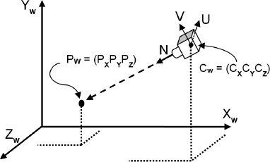
Figure 3.12
Camera orientation.
The necessary transforms are determined as follows:
1.Translate PW by the negative of the desired camera location.
2.Rotate PW by the negative of the desired camera orientation Euler angles.
We can build a single transform that does both the rotation and the translation in one matrix, called the viewing transform matrix, or V. The matrix V is produced by concatenating the two matrices T (a translation matrix containing the negative of the desired camera location) and R (a rotation matrix containing the negative of the desired camera orientation). In this case, working from right to left, we first translate world point P, then rotate it:
PC = R * ( T * PW )
As we saw earlier, the associative rule allows us to group the operations instead thusly:
PC = ( R * T ) * PW
If we save the concatenation R*T in the matrix V, the operation now looks like:
PC = V * PW
The complete computation, and the exact contents of matrices T and R, are shown in Figure 3.13 (we omit the derivation of matrix R—a derivation is available in [FV95]).
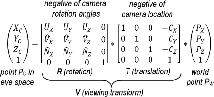
Figure 3.13
Deriving a view matrix.
More commonly, the V matrix is concatenated with the model matrix M to form a single model-view (MV) matrix:
Then, a point PM in its own model space is transformed directly to camera space in one step as follows:
PC = MV * PM
The advantage of this approach becomes clear when one considers that, in a complex scene, we will need to perform this transformation not on just one point, but on every vertex in the scene. By pre-computing MV, transforming each point into view space will require us to do just one matrix multiplication per vertex, rather than two. Later, we will see that we can extend this process to pre-computing several matrix concatenations, reducing the per-vertex computations considerably.
3.8PROJECTION MATRICES
Now that we have established the camera, we can examine projection matrices. Two important projection matrices that we will now examine are (a) perspective and (b) orthographic.
3.8.1The Perspective Projection Matrix
Perspective projection attempts to make a 2D picture appear 3D, by utilizing the concept of perspective to mimic what we see when we look at the real world. Objects that are close appear larger than objects that are far away, and in some cases, lines that are parallel in 3D space are no longer parallel when drawn with perspective.
Perspective was one of the great discoveries of the Renaissance era in the 1400–1500s, when artists started painting with more realism than did their predecessors.
An excellent example can be seen in Figure 3.14, “The Annunciation, with Saint Emidius” by Carlo Crivelli, painted in 1486 (currently held at the National Gallery in London [CR86]). The intense use of perspective is clear—the receding lines of the left-facing wall of the building on the right are slanted toward each other dramatically. This creates the illusion of depth and 3D space, and in the process lines that are parallel in reality are not parallel in the picture. Also, the people in the foreground are larger than the people in the background. While today we take these devices for granted, finding a transformation matrix to accomplish this requires some mathematical analysis.
Figure 3.14
The Annunciation, with Saint Emidius (Crivelli – 1486).
We achieve this effect by using a matrix transform that converts parallel lines into appropriate non-parallel lines. Such a matrix is called a perspective matrix or perspective transform, and is built by defining the four parameters of a view volume. Those parameters are (a) aspect ratio, (b) field of view, (c) projection plane or near clipping plane, and (d) far clipping plane.
Only objects between the near and far clipping planes are rendered. The near clipping plane also serves as the plane on which objects are projected, and is generally positioned close to the eye or camera (shown on the left in Figure 3.15). Selection of an appropriate value for the far clipping plane is discussed in Chapter 4. The field of view is the vertical angle of viewable space. The aspect ratio is the ratio width/height of the near and far clipping planes. The shape formed by these elements and shown in Figure 3.15 is called a frustum.
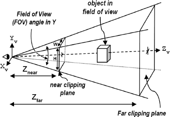
Figure 3.15
Perspective view volume or frustum.
The perspective matrix is used to transform points in 3D space to their appropriate position on the near clipping plane, and it is built by first computing values q, A, B, and C, and then using those values to construct the matrix, as shown in Figure 3.16 (and derived in [FV95]).
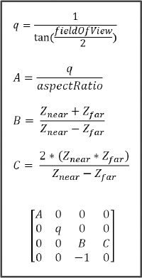
Figure 3.16
Building a perspective matrix.
Generating a perspective transform matrix is a simple matter, by simply inserting the described formulas into the cells of a 4x4 matrix. The GLM library also includes a function glm::perspective() for building a perspective matrix.
3.8.2The Orthographic Projection Matrix
In orthographic projection, parallel lines remain parallel; that is, perspective isn’t employed. Instead, objects that are within the view volume are projected directly, without any adjustment of their sizes due to their distances from the camera.

Figure 3.17
Orthographic projection.
An orthographic projection is a parallel projection in which all projections are at right angles with the projection plane. An orthographic matrix is built by defining the following parameters: (a) the distance Znear from the camera to the projection plane, (b) the distance Zfar from the camera to the far clipping plane, and (c) values for L, R, T, and B, with L and R corresponding to the X coordinates of the left and right boundaries of the projection plane respectively, and T and B corresponding to the Y coordinates of the top and bottom boundaries of the projection plane respectively. The orthographic projection matrix as derived in [FV95] is shown in Figure 3.18.
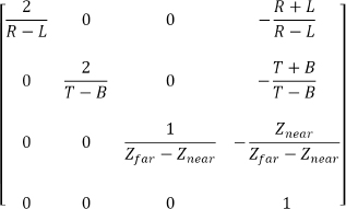
Figure 3.18
Orthographic projection matrix.
Not all parallel projections are orthographic, but others are out of the scope of this textbook.
Parallel projections don’t match what the eye sees when looking at the real world. But they are useful in a variety of situations, such as in casting shadows, performing 3D clipping, and in CAD (computer aided design)—the latter because they preserve measurement regardless of the placement of the objects. Regardless, the great majority of examples in this book use perspective projection.
3.9LOOK-AT MATRIX
The final transformation we will examine is the look-at matrix. This is handy when you wish to place the camera at one location and look toward a particular other location, as illustrated in Figure 3.19. Of course, it would be possible to achieve this using the methods we have already seen, but it is such a common operation that building one matrix transform to do it is often useful.
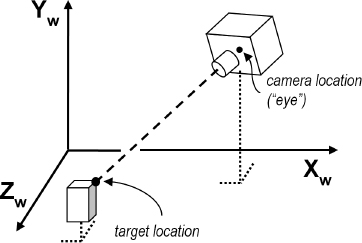
Figure 3.19
Elements of look-at.
A look-at transform still requires deciding on a camera orientation. We do this by specifying a vector approximating the general orientation desired (such as the world  axis). Typically, a sequence of cross products can be used to then generate a suitable set of forward, side, and up vectors for the desired camera orientation. Figure 3.20 shows the computations, starting with the camera location (eye), target location, and initial up vector
  , to build the look-at matrix, as derived in [FV95].
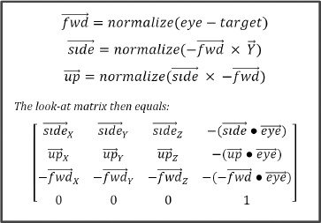
Figure 3.20
Look-At matrix.
We could encode this as a simple C++/OpenGL utility function that builds a look-at matrix, given specified values for camera location, target location, and the initial “up” vector  . Since GLM includes the function glm::lookAt() for building a look-at matrix, we will simply use that. This function will be useful later in this textbook, particularly in Chapter 8 when we generate shadows.
3.10GLSL FUNCTIONS FOR BUILDING MATRIX TRANSFORMS
Although GLM includes predefined functions for performing many of the 3D transformations covered in this chapter, such as translation, rotation, and scale, GLSL only includes basic matrix operations such as addition, concatenation, and so on. It is therefore sometimes necessary to write our own GLSL utility functions for building 3D transformation matrices when we need them to perform certain 3D computations in a shader. The appropriate datatype to hold such a matrix in GLSL is mat4.
The syntax for initializing mat4 matrices in GLSL loads values by columns. The first four values are put into the first column, the next four into the next column, and so forth, as illustrated in the following example:

which builds the translation matrix described previously in Figure 3.3.
Program 3.1 includes five GLSL functions for building 4x4 translation, rotation, and scale matrices, each corresponding to formulas given earlier in this chapter. We will use some of these functions later in the book.
Program 3.1 Building Transformation Matrices in GLSL
SUPPLEMENTAL NOTES
In this chapter we have seen examples of applying matrix transformations to points. Later, we will also want to apply these same transforms to vectors. In order to accomplish a transform on a vector V equivalent to applying some matrix transform M to a point, it is necessary in the general case to compute the inverse transpose of M, denoted (M-1)T, and multiply V by that matrix. In some cases, M=(M-1)T, and in those cases it is possible to simply use M. For example, the basic rotation matrices we have seen in this chapter are equal to their own inverse transpose and can be applied directly to vectors (and therefore also to points). Thus, the examples in this book sometimes use (M-1)T when applying a transform to a vector, and sometimes simply use M.
One of the things we haven’t discussed in this chapter is techniques for moving the camera smoothly through space. This is very useful, especially for games and CGI movies, but also for visualization, virtual reality, and for 3D modeling.
We didn’t include complete derivations for all of the matrix transforms that were presented (they can be found in other sources, such as [FV95]). We strove instead for a concise summary of the point, vector, and matrix operations necessary for doing basic 3D graphics programming. As this book proceeds, we will encounter many practical uses for the methods presented.
Exercises
3.1Modify Program 2.5 so that the vertex shader includes one of the buildRotate() functions from Program 3.1 and applies it to the points comprising the triangle. This should cause the triangle to be rotated from its original orientation. You don’t need to animate the rotation.
3.2(RESEARCH) At the end of Section 3.4 we indicated that Euler angles can in some cases lead to undesirable artifacts. The most common is called “gimbal lock.” Describe gimbal lock, give an example, and explain why gimbal lock can cause problems.
3.3(RESEARCH) One way of avoiding the artifacts that can manifest when using Euler angles is to use quaternions. We didn’t study quaternions; however, GLM includes several quaternion classes and functions. Do some independent study on quaternions and familiarize yourself with the related GLM quaternion capabilities.
[CR86] |
C. Crivelli, The Annunciation, with Saint Emidius, (National Gallery, London, England, 1486), accessed October 2018, https://www.nationalgallery.org.uk/paintings/carlo-crivelli-the-annunciation-with-saint-emidius |
[EU76] |
L. Euler, Formulae generals pro translatione quacunque coporum rigidorum (General formulas for the translation of arbitrary rigid bodies), (Novi Commentarii academiae scientiarum Petropolitanae 20, 1776). |
[FV95] |
J. Foley, A. van Dam, S. Feiner, and J. Hughes, Computer Graphics – Principles and Practice, 2nd ed. (Addison-Wesley, 1995). |
[KU98] |
J. B. Kuipers, Quaternions and Rotation Sequences (Princeton University Press, 1998). |