
SHADOWS

8.1THE IMPORTANCE OF SHADOWS
In Chapter 7, we learned how to add lighting to our 3D scenes. However, we didn’t actually add light; instead, we simulated the effects of light on objects—using the ADS model—and modified how we drew those objects accordingly.
The limitations of this approach become apparent when we use it to light more than one object in the same scene. Consider the scene in Figure 8.1, which includes both our brick-textured torus and a ground plane (the ground plane is the top of a giant cube with a grass texture from [LU16]).
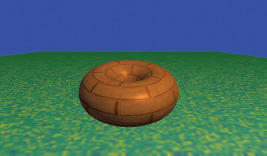
Figure 8.1
Scene without shadows.
At first glance our scene may appear reasonable. However, closer examination reveals that there is something very important missing. In particular, it is impossible to discern the distance between the torus and the large textured cube below it. Is the torus floating above the cube, or is it resting on top of the cube?
The reason we cannot answer this question is due to the lack of shadows in the scene. We expect to see shadows, and our brain uses shadows to help build a more complete mental model of the objects we see and where they are located.
Consider the same scene, shown in Figure 8.2, with shadows incorporated. It is now obvious that the torus is resting on the ground plane in the left example and floating above it in the right example.

Figure 8.2
Lighting with shadows.
8.2PROJECTIVE SHADOWS
A variety of interesting methods have been devised for adding shadows to 3D scenes. One method that is well-suited to drawing shadows on a ground plane (such as our image in Figure 8.1), and relatively computationally inexpensive, is called projective shadows. Given a point light source position (XL, YL, ZL), an object to render, and a plane on which the object’s shadow is to be cast, it is possible to derive a transformation matrix that will convert points (XW, YW, ZW) on the object to corresponding shadow points (XS, 0, ZS) on the plane. The resulting “shadow polygon” is then drawn, typically as a dark object blended with the texture on the ground plane, as illustrated in Figure 8.3.
The advantages of projective shadow casting are that it is efficient and simple to implement. However, it only works on a flat plane—the method can’t be used to cast shadows on a curved surface or on other objects. It is still useful for performance-intensive applications involving outdoor scenes, such as in many video games.
Development of projective shadow transformation matrices is discussed in [BL88], [AS14], and [KS16].
Figure 8.3
Projective shadow.
8.3SHADOW VOLUMES
Another important method, proposed by Crow in 1977, is to identify the spatial volume shadowed by an object and reduce the color intensity of polygons inside the intersection of the shadow volume with the view volume [CR77]. Figure 8.4 shows a cube in a shadow volume, so the cube would be drawn darker.
Shadow volumes have the advantage of being highly accurate, with fewer artifacts than other methods. However, finding the shadow volume and then computing whether each polygon is inside of it is computationally expensive even on modern GPU hardware. Geometry shaders can be used to generate shadow volumes, and the stencil buffer1 can be used to determine whether a pixel is within the volume. Some graphics cards include hardware support for optimizing certain shadow volume operations.
Figure 8.4
Shadow volume.
8.4SHADOW MAPPING
One the most practical and popular methods for casting shadows is called shadow mapping. Although it is not always as accurate as shadow volumes (and is often accompanied by pesky artifacts), shadow mapping is easier to implement, can be used in a wide variety of situations, and enjoys powerful hardware support.
We would be remiss if we failed to clarify our use of the word “easier” in the previous paragraph. Although shadow mapping is simpler than shadow volumes (both conceptually and in practice), it is by no means “easy”! Students often find shadow mapping among the most difficult techniques to implement in a 3D graphics course. Shader programs are by nature difficult to debug, and shadow mapping requires the perfect coordination of several components and shader modules. Be advised that successful implementation of shadow mapping will be greatly facilitated by liberal use of the debugging tools described earlier in Section 2.2.
Shadow mapping is based on a very simple and clever idea: namely, anything that cannot be seen by the light is in shadow. That is, if object #1 blocks the light from reaching object #2, it is the same as the light not being able to “see” object #2.
The reason this idea is so powerful is that we already have a method for determining if something can be “seen”—the hidden surface removal algorithm (HSR) using the Z-buffer, as described in Section 2.1.7. So, a strategy for finding shadows is to temporarily move the camera to the location of the light, apply the Z-buffer HSR algorithm, and then use the resulting depth information to find shadows.
Rendering our scene will require two passes: one to render the scene from the point of view of the light (but not actually drawing it to the screen), and a second pass to render it from the point of view of the camera. The purpose of pass one is to generate a Z-buffer from the light’s point of view. After completing pass one, we need to retain the Z-buffer and use it to help us generate shadows in pass two. Pass two actually draws the scene.
Our strategy is now becoming more refined:
•(Pass 1) Render the scene from the light’s position. The depth buffer then contains, for each pixel, the distance between the light and the nearest object to it.
•Copy the depth buffer to a separate "shadow buffer."
•(Pass 2) Render the scene normally. For each pixel, look up the corresponding position in the shadow buffer. If the distance to the point being rendered is greater than the value retrieved from the shadow buffer, then the object being drawn at this pixel is further from the light than the object nearest the light, and therefore this pixel is in shadow.
When a pixel is found to be in shadow, we need to make it darker. One simple and effective way of doing this is to render only its ambient lighting, ignoring its diffuse and specular components.
The method described above is often called “shadow buffering.” The term “shadow mapping” arises when, in the second step, we instead copy the depth buffer into a texture. When a texture object is used in this way, we will refer to it as a shadow texture, and OpenGL has support for shadow textures in the form of a sampler2DShadow type (discussed below). This allows us to leverage the power of hardware support for texture units and sampler variables (i.e., “texture mapping”) in the fragment shader to quickly perform the depth lookup in pass 2. Our revised strategy now is:
•(Pass 1) as before.
•Copy the depth buffer into a texture.
•(Pass 2) as before, except that the shadow buffer is now a shadow texture.
Let’s now implement these steps.
8.4.1Shadow Mapping (PASS ONE) – “Draw” Objects from Light Position
In step one, we first move our camera to the light’s position and then render the scene. Our goal here is not to actually draw the scene on the display, but to complete just enough of the rendering process that the depth buffer is properly filled. Thus, it will not be necessary to generate colors for the pixels, and so our first pass will utilize a vertex shader, but the fragment shader does nothing.
Of course, moving the camera involves constructing an appropriate view matrix. Depending on the contents of the scene, we will need to decide on an appropriate direction to view the scene from the light. Typically, we would want this direction to be toward the region that is ultimately rendered in pass 2. This is often application specific—in our scenes, we will generally be pointing the camera from the light to the origin.
Several important details need to be handled in pass one:
•Configure the buffer and shadow texture.
•Disable color output.
•Build a look-at matrix from the light toward the objects in view.
•Enable the GLSL pass one shader program, containing only the simple vertex shader shown in Figure 8.5 that expects to receive an MVP matrix. In this case, the MVP matrix will include the object’s model matrix M, the look-at matrix computed in the previous step (serving as the view matrix V), and the perspective matrix P. We call this MVP matrix “shadowMVP” because it is based on the point of view of the light rather than the camera. Since the view from the light isn’t actually being displayed, the pass one shader program’s fragment shader doesn’t do anything.
•For each object, create the shadowMVP matrix and call glDrawArrays(). It is not necessary to include textures or lighting in pass one, because objects are not rendered to the screen.
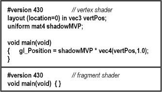
Figure 8.5
Shadow mapping pass 1 vertex and fragment shaders.
8.4.2Shadow Mapping (Intermediate Step) – Copying the Z-Buffer to a Texture
OpenGL offers two methods for putting Z-buffer depth data into a texture unit. The first method is to generate an empty shadow texture and then use the command glCopyTexImage2D() to copy the active depth buffer into the shadow texture.
The second method is to build a “custom framebuffer” back in pass one (rather than use the default Z-buffer) and attach the shadow texture to it using the command glFrameBufferTexture(). This command was introduced into OpenGL in version 3.0 to further support shadow mapping. When using this approach, it isn’t necessary to “copy” the Z-buffer into a texture, because the buffer already has a texture attached to it, and so the depth information is put into the texture by OpenGL automatically. This is the method we will use in our implementation.
8.4.3Shadow Mapping (PASS TWO) – Rendering the Scene with Shadows
Much of pass two will resemble what we saw in Chapter 7. Namely, it is here that we render our complete scene and all of the items in it, along with the lighting, materials, and any textures adorning the objects in the scene. We also need to add the necessary code to determine, for each pixel, whether or not it is in shadow.
An important feature of pass two is that it utilizes two MVP matrices. One is the standard MVP matrix that transforms object coordinates into screen coordinates (as seen in most of our previous examples). The other is the shadowMVP matrix that was generated in pass one for use in rendering from the light’s point of view—this will now be used in pass two for looking up depth information from the shadow texture.
A complication arises in pass two when we try to look up pixels in a texture map. The OpenGL camera utilizes a [-1..+1] coordinate space, whereas texture maps utilize a [0..1] space. A common solution is to build an additional matrix transform, typically called B, that converts (or “biases,” hence the name) from camera space to texture space. Deriving B is fairly simple—a scale by one-half followed by a translate by one-half.
The B matrix is as follows:
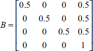
B is then concatenated onto the shadowMVP matrix for use in pass two, as follows:
shadowMVP2 = [B] [shadowMVP(pass1)]
Assuming that we use the method whereby a shadow texture has been attached to our custom framebuffer, OpenGL provides some relatively simple tools for determining whether each pixel is in shadow as we draw the objects. Here is a summary of the details handled in pass two:
•Build the “B” transform matrix for converting from light to texture space (actually, this is more appropriately done in init() ).
•Enable the shadow texture for lookup.
•Enable color output.
•Enable the GLSL pass two rendering program, containing both vertex and fragment shaders.
•Build the MVP matrix for the object being drawn based on the camera position (as normal).
•Build the shadowMVP2 matrix (incorporating the B matrix, as described earlier)—the shaders will need it to look up pixel coordinates in the shadow texture.
•Send the matrix transforms to shader uniform variables.
•Enable buffers containing vertices, normal vectors, and texture coordinates (if used), as usual.
•Call glDrawArrays().
In addition to their rendering duties, the vertex and fragment shaders have additional tasks:
•The vertex shader converts vertex positions from camera space to light space and sends the resulting coordinates to the fragment shader in a vertex attribute so that they will be interpolated. This makes it possible to retrieve the correct values from the shadow texture.
•The fragment shader calls the textureProj() function, which returns a 0 or 1 indicating whether or not the pixel is in shadow (this mechanism is explained later). If it is in shadow, the shader outputs a darker pixel by not including its diffuse and specular contributions.
Shadow mapping is such a common task that GLSL provides a special type of sampler variable called a sampler2DShadow (as previously mentioned) that can be attached to a shadow texture in the C++/OpenGL application. The textureProj() function is used to look up values from a shadow texture, and it is similar to texture() that we saw previously in Chapter 5, except that it uses a vec3 to index the texture rather than the usual vec2. Since a pixel coordinate is a vec4, it is necessary to project that onto 2D texture space in order to look up the depth value in the shadow texture map. As we will see in the following, textureProj() does all of this for us.
The remainder of the vertex and fragment shader code implements Blinn-Phong shading. These shaders are shown in Figures 8.6 and 8.7, with the added code for shadow mapping highlighted.
Let’s examine more closely how we use OpenGL to perform the depth comparison between the pixel being rendered and the value in the shadow texture. We start in the vertex shader with vertex coordinates in model space, which we multiply by shadowMVP2 to produce shadow texture coordinates that correspond to vertex coordinates projected into light space, previously generated from the light’s point of view. The interpolated (3D) light space coordinates (x,y,z) are used in the fragment shader as follows. The z component represents the distance from the light to the pixel. The (x,y) components are used to retrieve the depth information stored in the (2D) shadow texture. This retrieved value (the distance to the object nearest the light) is compared with z. This comparison produces a “binary” result that tells us whether the pixel we are rendering is further from the light than the object nearest the light (i.e., whether the pixel is in shadow).
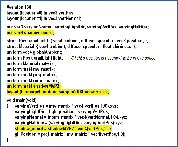
Figure 8.6
Shadow mapping pass 2 vertex shader.
Figure 8.7
Shadow mapping pass 2 fragment shader.
If in OpenGL we use glFrameBufferTexture() as described earlier, and we enable depth testing, then using a sampler2DShadow and textureProj() as shown in the fragment shader (Figure 8.7) will do exactly what we need. That is, textureProj() will output either 0.0 or 1.0 depending on the depth comparison. Based on this value, we can then in the fragment shader omit the diffuse and specular contributions when the pixel is further from the light than the object nearest the light, effectively creating the shadow when appropriate. An overview is shown in Figure 8.8.
We are now ready to build our C++/OpenGL application to work with the previously described shaders.
Figure 8.8
Automatic depth comparison.
8.5A SHADOW MAPPING EXAMPLE
Consider the scene in Figure 8.9 that includes a torus and a pyramid. A positional light has been placed on the left (note the specular highlights).
The pyramid should be casting a shadow on the torus.
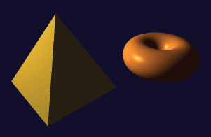
Figure 8.9
Lighted scene without shadows.
To clarify the development of the example, our first step will be to render pass one to the screen to make sure it is working properly. To do this, we will temporarily add a simple fragment shader (it will not be included in the final version) to pass one that just outputs a constant color (e.g., red); for example:
#version 430
out vec4 fragColor;
void main(void)
{ fragColor = vec4(1.0, 0.0, 0.0, 0.0);
}
Let’s assume that the origin of the previous scene is situated at the center of the figure, in between the pyramid and the torus. In pass one we place the camera at the light’s position (at the left in Figure 8.10) and point it toward (0,0,0). If we then draw the objects in red, it produces the output shown at the right in Figure 8.10. Note the torus near the top—from this vantage point it is partially behind the pyramid.

Figure 8.10
Pass one: Scene (left) from light’s point of view (right).
The complete two-pass C++/OpenGL code with lighting and shadow mapping is shown in Program 8.1.
Program 8.1 Shadow Mapping
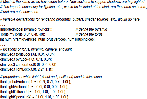
Program 8.1 shows the relevant portions of the C++/OpenGL application that interact with the pass one and pass two shaders previously detailed. Not shown are the usual modules for reading in and compiling the shaders, building the models and their related buffers, installing the positional light’s ADS characteristics in the shaders, and performing the perspective and look-at matrix computations. Those are unchanged from previous examples.
8.6SHADOW MAPPING ARTIFACTS
Although we have implemented all of the basic requirements for adding shadows to our scene, running Program 8.1 produces mixed results, as shown in Figure 8.11.
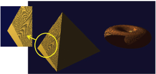
Figure 8.11
Shadow “acne.”
The good news is that our pyramid is now casting a shadow on the torus! Unfortunately, this success is accompanied by a severe artifact. There are wavy lines covering many of the surfaces in the scene. This is a common by-product of shadow mapping, and is called shadow acne or erroneous self-shadowing.
Shadow acne is caused by rounding errors during depth testing. The texture coordinates computed when looking up the depth information in a shadow texture often don’t exactly match the actual coordinates. Thus, the lookup may return the depth for a neighboring pixel, rather than the one being rendered. If the distance to the neighboring pixel is further, then our pixel will appear to be in shadow even if it isn’t.
Shadow acne can also be caused by differences in precision between the texture map and the depth computation. This too can lead to rounding errors and subsequent incorrect assessment of whether or not a pixel is in shadow.
Fortunately, fixing shadow acne is fairly easy. Since shadow acne typically occurs on surfaces that are not in shadow, a simple trick is to move every pixel slightly closer to the light during pass one, and then move them back to their normal positions for pass two. This is usually sufficient to compensate for either type of rounding error. An easy way is to call glPolygonOffset() in the display() function, as shown in Figure 8.12 (highlighted).
Adding these few lines of code to our display() function improves the output of our program considerably, as shown in Figure 8.13. Note also that with the artifacts gone, we can now see that the inner circle of the torus displays a small correctly cast shadow on itself.
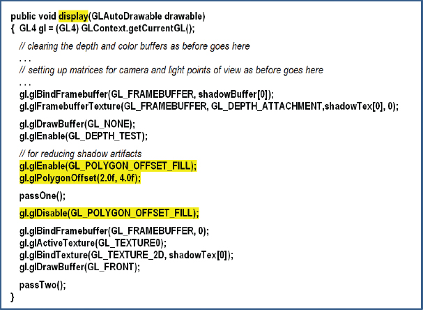
Figure 8.12
Combating shadow acne.
Figure 8.13
Rendered scene with shadows.
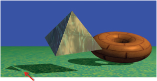
Figure 8.14
“Peter Panning.”
Although fixing shadow acne is easy, sometimes the repair causes new artifacts. The “trick” of moving the object before pass one can sometimes cause a gap to appear inside an object’s shadow. An example of this is shown in Figure 8.14. This artifact is often called “Peter Panning,” because sometimes it causes the shadow of a resting object to inappropriately separate from the object’s base (thus making portions of the object’s shadow detach from the rest of the shadow, reminiscent of J. M. Barrie’s character Peter Pan [PP16]). Fixing this artifact requires adjusting the glPolygonOffset() parameters. If they are too small, shadow acne can appear; if too large, Peter Panning happens.
There are many other artifacts that can happen during shadow mapping. For example, shadows can repeat as a result of the region of the scene being rendered in pass one (into the shadow buffer) being different from the region of the scene rendered in pass two (they are from different vantage points). Because of this difference, those portions of the scene rendered in pass two that fall outside the region rendered in pass one will attempt to access the shadow texture using texture coordinates outside of the range [0..1]. Recall that the default behavior in this case is GL_REPEAT, which can result in incorrectly duplicated shadows.
One possible solution is to add the following lines of code to setupShadowBuffers(), to set the texture wrap mode to “clamp to edge”:
glTexParameteri(GL_TEXTURE_2D, GL_TEXTURE_WRAP_S, GL_CLAMP_TO_EDGE);
glTexParameteri(GL_TEXTURE_2D, GL_TEXTURE_WRAP_T, GL_CLAMP_TO_EDGE);
This causes values outside of a texture edge to be clamped to the value at edge (instead of repeating). Note that this approach can introduce its own artifacts, namely, when a shadow exists at the edge of the shadow texture, clamping to the edge can produce a “shadow bar” extending to the edge of the scene.
Another common error is jagged shadow edges. This can happen when the shadow being cast is significantly larger than the shadow buffer can accurately represent. This usually depends on the location of the objects and light(s) in the scene. In particular, it commonly occurs when the light source is relatively distant from the objects involved. An example is shown in Figure 8.15.
Figure 8.15
Jagged shadow edges.
Eliminating jagged shadow edges is not as simple as for the previous artifacts. One technique is to move the light position closer to the scene during pass one, and then return it to the correct position in pass two. Another approach that is often effective is to employ one of the “soft shadow” methods that we will discuss next.
8.7SOFT SHADOWS
The methods presented thus far are limited to producing hard shadows. These are shadows with sharp edges. However, most shadows that occur in the real world are soft shadows. That is, their edges are blurred to various degrees. In this section, we will explore the appearance of soft shadows as they occur in the real world and then describe a commonly used algorithm for simulating them in OpenGL.
8.7.1Soft Shadows in the Real World
There are many causes of soft shadows, and there are many types of soft shadows. One thing that commonly causes soft shadows in nature is that real-world light sources are rarely points—more often they occupy some area. Another cause is the accumulation of imperfections in materials and surfaces, and the role that the objects themselves play in generating ambient light through their own reflective properties.
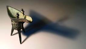
Figure 8.16
Soft shadow real-world example.
Figure 8.16 shows a photograph of an object casting a soft shadow on a table top. Note that this is not a 3D computer rendering, but an actual photograph of an object, taken in the home of one of the authors.
There are two aspects to note about the shadow in Figure 8.16:
•The shadow is “softer” the further it is from the object and “harder” the closer it is to the object. This is apparent when comparing the shadow near the legs of the object versus the wider portion of the shadow at the right region of the image.
•The shadow appears slightly darker the closer it is to the object.
The dimensionality of the light source itself can lead to soft shadows. As shown in Figure 8.17, the various regions across the light source cast slightly different shadows. Those areas where the various shadows differ are called the penumbra, and comprise the soft regions at the edges of the shadow.
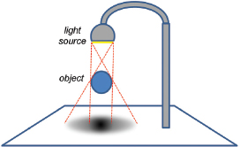
Figure 8.17
Soft shadow penumbra effect.
8.7.2Generating Soft Shadows – Percentage Closer Filtering (PCF)
There are various ways of simulating the penumbra effect to generate soft shadows in software. One of the simplest and most common is called Percentage Closer Filtering (PCF). In PCF, we sample the shadow texture at several surrounding locations to estimate what percentage of nearby locations are in shadow. Depending on how many of the nearby locations are in shadow, we increase or decrease the degree of lighting contribution for the pixel being rendered. The entire computation can be done in the fragment shader, and that is the only place where we have to change any of the code. PCF also can be used to reduce jagged line artifacts.
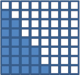
Figure 8.18
Hard shadow rendering.
Before we study the actual PCF algorithm, let’s first look at a simple similar motivating example to illustrate the goal of PCF. Consider the set of output fragments (pixels) shown in Figure 8.18, whose colors are being computed by the fragment shader.
Suppose that the darkened pixels are in shadow, as computed using shadow mapping. Instead of simply rendering the pixels as shown (i.e., with or without the diffuse and specular components included), suppose that we had access to neighboring pixel information, so that we could see how many of the neighboring pixels are in shadow. For example, consider the particular pixel highlighted in yellow in Figure 8.19, which according to Figure 8.18 is not in shadow.

Figure 8.19
PCF sampling for a particular pixel.
In the nine-pixel neighborhood of the highlighted pixel, three of the pixels are in shadow and six are not. Thus, the color of the rendered pixel could be computed as the sum of the ambient contribution at that pixel, plus six-ninths of the diffuse and specular contributions, resulting in a fairly (but not completely) brightened pixel. Repeating this process throughout the grid would produce pixel colors approximately as shown in Figure 8.20. Note that for those pixels whose neighborhoods are entirely in (or out of) shadow, the resulting color is the same as for standard shadow-mapping.
Unlike the example just shown, implementations of PCF do not sample every pixel within a certain vicinity of the pixel being rendered. There are two reasons for this: (a) we’d like to perform this computation in the fragment shader, but the fragment shader does not have access to other pixels; and (b) obtaining a sufficiently broad penumbra effect (say, ten to twenty pixels wide) would require sampling hundreds of nearby pixels for each pixel being rendered.
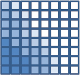
Figure 8.20
Soft shadow rendering.
PCF addresses these two issues as follows. First, rather than attempting to access nearby pixels, we instead sample nearby texels in the shadow map. The fragment shader can do this because even though it doesn’t have access to nearby pixel values, it does have access to the entire shadow map. Second, to achieve a sufficiently broad penumbra effect, a moderate number of nearby shadow map texels are sampled, each at some modest distance from the texel corresponding to the pixel being rendered.
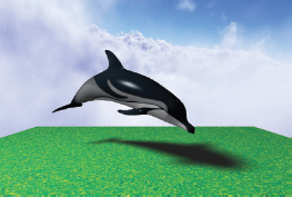
Figure 8.21
Soft shadow rendering – 64 samples per pixel.
The width of the penumbra and the number of points sampled can be tuned depending on the scene and the performance requirements. For example, the image shown in Figure 8.21 was generated using PCF, with each pixel’s brightness determined by sampling 64 nearby shadow map texels at various distances from the pixel’s texel.
The accuracy or smoothness of our soft shadows depends on the number of nearby texels sampled. Thus, there is a tradeoff between performance and quality—the more points sampled, the better the results, but the more computational overhead is incurred. Depending on the complexity of the scene and the framerate required for a given application, there is often a corresponding practical limit to the quality that can be achieved. Samping 64 points per pixel, such as in Figure 8.21, is usually impractical.
A commonly used algorithm for implementing PCF is to sample four nearby texels per pixel, with the samples selected at specified offset distances from the texel which corresponds to the pixel. As we process each pixel, we alter the offsets used to determine which four texels are sampled. Altering the offsets in a staggered manner is sometimes called dithering, and aims to make the soft shadow boundary appear less “blocky” than it ordinarily would given the small number of sample points.
A common approach is to assume one of four different offset patterns—we can choose which pattern to use for a given pixel by computing the pixel’s glFragCoord mod 2. Recall that glFragCoord is of type vec2, containing the x and y coordinates of the pixel location; the result of the mod computation is then one of four values: (0,0), (0,1), (1,0), or (1,1). We use this result to select one of our four different offset patterns in texel space (i.e., in the shadow map).
The offset patterns are typically specified in the x and y directions with different combinations of -1.5, -0.5, +0.5, and +1.5 (these can also be scaled as desired). More specifically, the four usual offset patterns for each of the cases resulting from the glFragCoord mod 2 compuation are:

Sx and Sy refer to the location (Sx, Sy) in the shadow map corresponding to the pixel being rendered, identified as shadow_coord in the code examples throughout this chapter. These four offset patterns are illustrated in Figure 8.22, with each case shown in a different color. In each case, the texel corresponding to the pixel being rendered is at the origin of the graph for that case. Note that when shown together in Figure 8.23, the staggering/dithering of the offsets is apparent.

Figure 8.22
Dithered four-pixel PCF sampling cases.
Let’s walk through the entire computation for a particular pixel. Assume the pixel being rendered is located at glFragCoord = (48,13). We start by determining the four shadow map sample points for the pixel. To do that, we would compute vec2(48,13) mod 2, which equals (0,1). From that we would choose the offsets shown for case (0,1), shown in green in Figure 8.22, and the specific points to be sampled in the shadow map (assuming that no scaling of the offsets has been specified) would be:
•(shadow_coord.x–1.5, shadow_coord.y+0.5)
•(shadow_coord.x–1.5, shadow_coord.y–1.5)
•(shadow_coord.x+0.5, shadow_coord.y+0.5)
•(shadow_coord.x+0.5, shadow_coord.y–1.5)
(Recall that shadow_coord is the location of the texel in the shadow map corresponding to the pixel being rendered—shown as a white circle in Figures 8.22 and 8.23.)
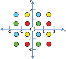
Figure 8.23
Dithered four-pixel PCF sampling (four cases shown together).
We next call textureProj() on each of these four points, which in each case returns either 0.0 or 1.0 depending on whether or not that sampled point is in shadow. We sum the four results and divide by 4.0 to determine the percentage of sampled points which are in shadow. This percentage is then used as a multiplier to determine the amount of diffuse and specular lighting to be applied when rendering the current pixel.
Despite the small sampling size—only four samples per pixel—this dithered approach can often produce surprisingly good soft shadows. Figure 8.24 was generated using four-point dithered PCF. While not quite as good as the 64-point sampled version shown previously in Figure 8.21, it renders considerably faster.
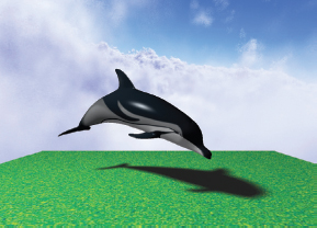
Figure 8.24
Soft shadow rendering – four samples per pixel, dithered.
In the next section, we develop the GLSL fragment shader that produced both this four-sample dithered PCF soft shadow and the previously shown 64-sample PCF soft shadow.
8.7.3A Soft Shadow/PCF Program
As mentioned earlier, the soft shadow computation can be done entirely in the fragment shader. Program 8.2 shows the fragment shader that replaces the one in Figure 8.7. The PCF additions are highlighted.
Program 8.2 Percentage Closer Filtering (PCF)

The fragment shader shown in Program 8.2 contains code for both the four-sample and 64-sample PCF soft shadows. First, a function lookup() is defined to make the sampling process more convenient. It makes a call to the GLSL function textureProj() that does a lookup in the shadow texture, but is offset by a specified amount (ox,oy). The offset is multiplied by 1/windowsize, which here we have simply hardcoded to .001, assuming a window size of 1000×1000 pixels.2
The four-sample dithered computation appears highlighted in main(), and it follows the algorithm described in the previous section. A scale factor swidth has been added that can be used to adjust the size of the “soft” region at the edge of the shadows.
The 64-sample code follows and is commented out. It can be used instead of the four-sample computation by un-commenting it and instead commenting out the four-sample code. The swidth scale factor in the 64-sample code is used as a step size in the nested loop that samples points at various distances from the pixel being rendered. For example, using the value of swidth shown (2.5), points would be sampled along each axis at distances of 1.25, 3.75, 6.25, and 8.25 in both directions—then scaled based on the window size (as described earlier) and used as texture coordinates into the shadow texture. With this many samples, dithering is generally not necessary to obtain good results.
Figure 8.25 shows our running torus/pyramid shadow-mapping example, incorporating PCF soft shadowing with the fragment shader from Program 8.2, for both four-sample and 64-sample approaches. The value chosen for swidth is scene dependent; for the torus/pyramid example it was set to 2.5, whereas for the dolphin example shown previously in Figure 8.21, swidth was set to 8.0.
Figure 8.25
PCF Soft shadow rendering—4 samples per pixel, dithered (left), and 64 samples per pixel, not dithered (right).
SUPPLEMENTAL NOTES
In this chapter we have only given the most basic of introductions to the world of shadows in 3D graphics. Even using the basic shadow mapping methods presented here will likely require further study if used in more complex scenes.
For example, when adding shadows to a scene in which some of the objects are textured, it is necessary to ensure that the fragment shader properly distinguishes between the shadow texture and other textures. A simple way of doing this is to bind them to different texture units, such as:
layout (binding = 0) uniform sampler2DShadow shTex;
layout (binding = 1) uniform sampler2D otherTexture;
Then, the C++/OpenGL application can refer to the two samplers by their binding values.
When a scene utilizes multiple lights, multiple shadow textures are necessary—one for each light source. In addition, a pass one will need to be performed for each one, with the results blended in pass two.
Although we have used perspective projection at each phase of shadow mapping, it is worth noting that orthographic projection is often preferred when the light source is distant and directional, rather than the positional light we utilized.
Generating realistic shadows is a rich and complex area of computer graphics, and many of the available techniques are outside the scope of this text. Readers interested in more detail are encouraged to investigate more specialized resources such as [ES12], [GP10], and [MI16].
Section 8.7.3 contains an example of a GLSL function (aside from the “main”). As in the C language, functions must be defined before (or “above”) where they are called, or else a forward declaration must be provided. In the example, a forward declaration isn’t required because the function has been defined above the call to it.
Exercises
8.1In Program 8.1, experiment with different settings for glPolygonOffset(), and observe the effects on shadow artifacts such as Peter Panning.
8.2(PROJECT) Modify Program 8.1 so that the light can be positioned by moving the mouse, similar to Exercise 7.1. You will probably notice that some lighting positions exhibit shadow artifacts, while others look fine.
8.3(PROJECT) Add animation to Program 8.1, such that either the objects or the light (or both) move around on their own—such as one revolving around the other. The shadow effects will be more pronounced if you add a ground plane to the scene, such as the one illustrated in Figure 8.14.
8.4(PROJECT) Modify Program 8.2 to replace the hardcoded values 0.001 in the lookup() function with the more accurate values of 1.0/shadowbufferwidth and 1.0/shadowbufferheight. Observe to what degree this change makes a difference (or not) for various window sizes.
8.5(RESEARCH) More sophisticated implementations of Percentage Closer Filtering (PCF) take into account the relative distance between the light and the shadow versus the light and the occluder. Doing this can make soft shadows more realistic, by allowing their penumbra to change in size as the light moves closer or further from the occluder (or as the occluder moves closer or further from the shadow). Study existing methods for incorporating this capability, and add it to Program 8.2.
References
[AS14] |
E. Angel and D. Shreiner, Interactive Computer Graphics: A Top-Down Approach with WebGL, 7th ed. (Pearson, 2014). |
J. Blinn, “Me and My (Fake) Shadow,” IEEE Computer Graphics and Applications 8, no. 2 (1988). | |
[CR77] |
F. Crow, “Shadow Algorithms for Computer Graphics,” Proceedings of SIGGRAPH ’77 11, no. 2 (1977). |
[ES12] |
E. Eisemann, M. Schwarz, U. Assarsson, and M. Wimmer, Real-Time Shadows (CRC Press, 2012). |
[GP10] |
GPU Pro (series), ed. Wolfgang Engel (A. K. Peters, 2010–2016). |
[KS16] |
J. Kessenich, G. Sellers, and D. Shreiner, OpenGL Programming Guide: The Official Guide to Learning OpenGL, Version 4.5 with SPIR-V, 9th ed. (Addison-Wesley, 2016). |
[LO12] |
Understanding OpenGL’s Matrices, Learn OpenGL ES (2012), accessed October 2018, http://www.learnopengles.com/tag/perspective-divide/ |
[LU16] |
F. Luna, Introduction to 3D Game Programming with DirectX 12, 2nd ed. (Mercury Learning, 2016). |
[MI16] |
Common Techniques to Improve Shadow Depth Maps (Microsoft Corp., 2016), accessed October 2018, https://msdn.microsoft.com/en-us/library/windows/desktop/ee416324(v=vs.85).aspx |
[PP16] |
Peter Pan, Wikipedia, accessed October 2018, https://en.wikipedia.org/wiki/Peter_Pan |
1The stencil buffer is a third buffer—along with the color buffer and the z-buffer—accessible through OpenGL. The stencil buffer is not described in this textbook.
2We have also multiplied the offset by the w component of the shadow coordinate, because OpenGL automatically divides the input coordinate by w during texture lookup. This operation, called perspective divide, is one which we have ignored up to this point. It must be accounted for here. For more information on perspective divide, see [LO12].