GEOMETRY SHADERS
13.1Per-Primitive Processing in OpenGL
Immediately following tessellation in the OpenGL pipeline is the geometry stage. Here, the programmer has the option of including a geometry shader. This stage actually pre-dates tessellation; it became part of the OpenGL core at version 3.2 (in 2009).
Like tessellation, geometry shaders enable the programmer to manipulate groups of vertices, in ways that are impossible to do in a vertex shader. In some cases, a task might be accomplished using either a tessellation shader or a geometry shader, as their capabilities overlap in some ways.
13.1PER-PRIMITIVE PROCESSING IN OPENGL
The geometry shader stage is situated between tessellation and rasterization, within the segment of the pipeline devoted to primitive processing (refer back to Figure 2.2). Whereas vertex shaders enable the manipulation of one vertex at a time, and fragment shaders enable the manipulation of one fragment (essentially one pixel) at a time, geometry shaders enable manipulation of one primitive at a time.
Recall that primitives are the basic building blocks in OpenGL for drawing objects. Only a few types of primitives are available; we will focus primarily on geometry shaders that manipulate triangles. Thus, when we say that a geometry shader can manipulate one primitive at a time, we usually mean that the shader has access to all three vertices of a triangle at a time. Geometry shaders allow you to:
•access all vertices in a primitive at once, then
•output the same primitive unchanged, or
•output the same primitive with modified vertex locations, or
•output a different type of primitive, or
•output additional primitives, or
•delete the primitive (not output it at all).
Similar to the tessellation evaluation shader, incoming vertex attributes are accessible in a geometry shader as arrays. However, in a geometry shader, incoming attribute arrays are indexed only up to the primitive size. For example, if the primitives are triangles, then the available indices are 0, 1, and 2. Accessing the vertices themselves is done using the predefined array gl_in, as follows:
gl_in[2].gl_Position // position of the 3rd vertex
Also similar to the tessellation evaluation shader, the geometry shader’s output vertex attributes are all scalars. That is, the output is a stream of individual vertices (their positions and other attribute variables, if any) that form primitives.
There is a layout qualifier used to set the primitive input/output types and the output size.
The special GLSL command EmitVertex() specifies that a vertex is to be output. The special GLSL command EndPrimitive() indicates the completion of building a particular primitive.
The built-in variable gl_PrimitiveIDIn is available and holds the ID of the current primitive. The ID numbers start at 0 and count up to the number of primitives minus 1.
We will explore four common categories of operations:
•altering primitives
•deleting primitives
•adding primitives
•changing primitive types
Geometry shaders are convenient for changing the shape of an object when that change can be affected through isolated changes to the primitives (typically triangles).
Consider, for example, the torus we rendered previously in Figure 7.12. Suppose that torus represented an inner tube (such as for a tire), and we want to “inflate” it. Simply applying a scale factor in the C++/OpenGL code won’t accomplish this, because its fundamental shape wouldn’t change. Giving it the appearance of being “inflated” requires also making the inner hole smaller as the torus stretches into the empty center space.
One way of doing this would be to add the surface normal vector to each vertex. While it is true that this could be done in the vertex shader, let’s do it in the geometry shader, for practice. Program 13.1 shows the GLSL geometry shader code. The other modules are the same as for Program 7.3, with a few minor changes: the fragment shader input names now need to reflect the geometry shader outputs (for example, varyingNormal becomes varyingNormalG), and the C++/OpenGL application needs to compile the geometry shader and attach it to the shader program prior to linking. The new shader is specified as being a geometry shader as follows:
GLuint gShader = glCreateShader(GL_GEOMETRY_SHADER);
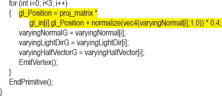
Program 13.1 Geometry Shader: Altering Vertices
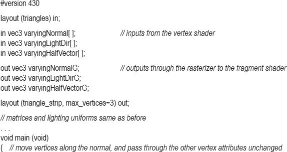
Note in Program 13.1 that the input variables corresponding to the output variables from the vertex shader are declared as arrays. This provides the programmer a mechanism for accessing each of the vertices in the triangle primitive and their attributes using the indices 0, 1, and 2. We wish to move those vertices outward along their surface normals. Both the vertices and the normals have already been transformed to view space in the vertex shader. We add a fraction of the normal to each of the incoming vertex positions (gl_in[i].gl_Position) and then apply the projection matrix to the result, producing each output gl_Position.
Note the use of the GLSL call EmitVertex() that specifies when we have finished computing the output gl_Position and its associated vertex attributes and are ready to output a vertex. The EndPrimitive() call specifies that we have completed the definition of a set of vertices comprising a primitive (in this case, a triangle). The result is shown in Figure 13.1.

Figure 13.1
“Inflated” torus with vertices altered by geometry shader.
The geometry shader includes two layout qualifiers. The first specifies the input primitive type and must be compatible with the primitive type in the C++-side glDrawArrays() or glDrawElements() call. The options are as follows:
The various OpenGL primitive types (including “strip” and “fan” types) were described in Chapter 4. “Adjacency” types were introduced in OpenGL for use with geometry shaders, and they allow access to vertices adjacent to the primitive. We don’t use them in this book, but they are listed for completeness.
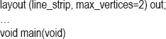
The output primitive type must be points, line_strip, or triangle_strip. Note that the output layout qualifier also specifies the maximum number of vertices the shader outputs in each invocation.
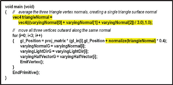
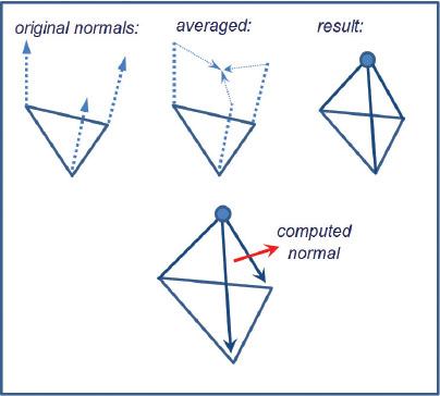
This particular alteration to the torus could have been done more easily in the vertex shader. However, suppose that instead of moving each vertex outward along its own surface normal, we wished instead to move each triangle outward along its surface normal, in effect “exploding” the torus triangles outward. The vertex shader cannot do that, because computing a normal for the triangle requires averaging the vertex normals of all three triangle vertices, and the vertex shader only has access to the vertex attributes of one vertex in the triangle at a time. We can, however, do this in the geometry shader, because the geometry shader does have access to all three vertices in each triangle. We average their normals to compute a surface normal for the triangle, then add that averaged normal to each of the vertices in the triangle primitive. Figures 13.2, 13.3, and 13.4 show the averaging of the surface normals, the modified geometry shader main() code, and the resulting output respectively.
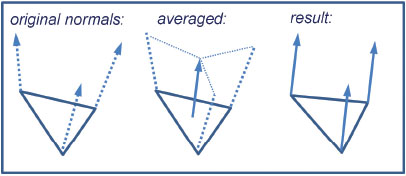
Figure 13.2
Applying averaged triangle surface normal to triangle vertices.
Figure 13.3
Modified geometry shader for “exploding” the torus.
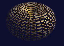
Figure 13.4
“Exploded” torus.
The appearance of the “exploded” torus can be improved by ensuring that the inside of the torus is also visible (normally those triangles are culled by OpenGL because they are “back-facing”). One way of doing this is to render the torus twice, once in the normal manner and once with winding order reversed (reversing the winding order effectively switches which faces are front-facing and which are back-facing). We also send a flag to the shaders (in a uniform) to disable diffuse and specular lighting on the back-facing triangles to make them less prominent. The changes to the code are as follows.

The resulting “exploded” torus, including back faces, is shown in Figure 13.5.

Figure 13.5
“Exploded” torus including back faces.
13.3DELETING PRIMITIVES
A common use for geometry shaders is to build richly ornamental objects out of simple ones, by judiciously deleting some of the primitives. For example, removing some of the triangles from our torus can turn it into a sort of complex latticed structure that would be more difficult to model from scratch. A geometry shader that does this is shown in Program 13.2, and the output is shown in Figure 13.6.
Program 13.2 Geometry: Delete Primitives
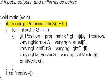
Figure 13.6
Geometry shader: primitive deletion.
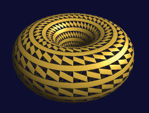
Figure 13.7
Primitive deletion showing back faces.
No other changes to the code are necessary. Note the use of the mod function—all vertices are passed through except those in the first of every three primitives, which is ignored. Here too, rendering the back-facing triangles can improve realism, as shown in Figure 13.7.
13.4ADDING PRIMITIVES
Perhaps the most interesting and powerful use of geometry shaders is for adding additional vertices and/or primitives to a model being rendered. This makes it possible to do such things as increase the detail in an object to improve height mapping, or to change the shape of an object completely.
Consider the following example, where we change each triangle in the torus to a tiny triangular pyramid.
Our strategy, similar to our previous “exploded” torus example, is illustrated in Figure 13.8. The vertices of an incoming triangle primitive are used to define the base of a pyramid. The walls of the pyramid are constructed of those vertices and of a new point (called the “spike point”) computed by averaging the normals of the original vertices. New normal vectors are then computed for each of the three “sides” of the pyramid by taking the cross product of two vectors from the spike point to the base.
Figure 13.8
Converting triangles to pyramids.
The geometry shader in Program 13.3 does this for each triangle primitive in the torus. For each incoming triangle, it outputs three triangle primitives, for a total of nine vertices. Each new triangle is built in the function makeNewTriangle(), which is called three times. It computes the normal for the specified triangle, then calls the function setOutputValues() to assign the appropriate output vertex attributes for each vertex emitted. After emitting all three vertices, it calls EndPrimitive(). To ensure that the lighting is performed accurately, new values of the light direction vector are computed for each newly created vertex.
Program 13.3 Geometry: Add Primitives


Figure 13.9
Geometry shader: primitive addition.
The resulting output is shown in Figure 13.9. If the spike length (sLen) variable is increased, the added surface “pyramids” would be taller. However, they could appear unrealistic in the absence of shadows. Adding shadow-mapping to Program 13.3 is left as an exercise for the reader.
Careful application of this technique can enable the simulation of spikes, thorns, and other fine surface protrusions, as well as the reverse, such as indentations and craters ([DV14], [TR13], and [KS16]).
13.5CHANGING PRIMITIVE TYPES
OpenGL allows for switching primitive types in a geometry shader. A common use for this feature is to convert input triangles into one or more output line segments, simulating fur or hair. Although hair remains one of the more difficult real-world items to generate convincingly, geometry shaders can help make real-time rendering achievable in many cases.
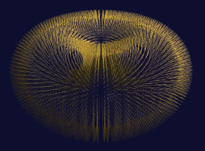
Figure 13.10
Changing triangle primitives to line primitives.
Program 13.4 shows a geometry shader that converts each incoming three-vertex triangle to an outward-facing two-vertex line segment. It starts by computing a starting point for the strand of hair by averaging the triangle vertex locations, thus generating the centroid of the triangle. It then uses the same “spike point” from Program 13.3 as the hair’s ending point. The output primitive is specified as a line strip with two vertices, the first vertex being the start point, and the second vertex being the end point. The result is shown in Figure 13.10, for a torus instantiated with a dimensionality of seventy-two slices.
Of course, this is merely the starting point for generating fully realistic hair. Making the hair bend or move would require several modifications, such as generating more vertices for the line strip and computing their positions along curves and/or incorporating randomness. Lighting is complicated by the lack of an obvious surface normal for a line segment; in this example, we simply assigned the normal to be the same as the original triangle’s surface normal.
Program 13.4 Geometry: Changing Primitive Types
SUPPLEMENTAL NOTES
One of the appeals of geometry shaders is that they are relatively easy to use. Although many applications for which geometry shaders are used could be achieved using tessellation, the mechanism of geometry shaders often makes them easier to implement and debug. Of course, the relative fit of geometry versus tessellation depends on the particular application.
Generating convincing hair or fur is challenging, and there is a wide range of techniques employed depending on the application. In some cases, simple texturing is adequate, and/or the use of tessellation or geometry shaders such as the basic technique shown in this chapter. When greater realism is required, movement (animation) and lighting become tricky. Two dedicated tools for hair and fur generation are HairWorks, which is part of the NVIDIA GameWorks suite [GW18], and TressFX, which was developed by AMD [TR18]. The former works with both OpenGL and DirectX, whereas the latter works only with DirectX. Examples of using TressFX can be found in [GP14].
13.1Modify Program 13.1 so that it moves each vertex slightly toward the center of its primitive triangle. The result should look similar to the exploded torus in Figure 13.5, but without the overall change in torus size.
13.2Modify Program 13.2 so that it deletes every other primitive, or every fourth primitive (rather than every third primitive), and observe the effect on the resulting rendered torus. Also, try changing the dimensionality of the instantiated torus to a value that is not a multiple of three (such as 40), while still deleting every third primitive. There are many possible effects.
13.3(PROJECT) Modify Program 13.4 to additionally render the original torus. That is, render both a lighted torus (as previously done in Chapter 7) and the outgoing line segments (using a geometry shader) so that the “hair” looks like it is coming out of the torus.
13.4(RESEARCH & PROJECT) Modify Program 13.4 so that it produces outward-facing line segments with more than two vertices, arranged so as to make the line segments appear to bend slightly.
References
[DV14] |
J. deVries, LearnOpenGL, 2014, accessed October 2018, http://www.learnopengl.com/ |
[GP14] |
GPU Pro 5: Advanced Rendering Techniques, ed. W. Engel (CRC Press, 2014). |
[GW18] |
NVIDIA GameWorks Suite, 2018, accessed May 2018, https://developer.nvidia.com/gameworks |
[KS16] |
J. Kessenich, G. Sellers, and D. Shreiner, OpenGL Programming Guide: The Official Guide to Learning OpenGL, Version 4.5 with SPIR-V, 9th ed. (Addison-Wesley, 2016). |
[TR13] |
P. Trettner, Prototype Grass (blog), 2013, accessed October 2018, https://upvoid.com/devblog/2013/02/prototype-grass/ |
[TR18] |
TressFX Hair, AMD, 2018, accessed May 2018, https://www.amd.com/en/technologies/tressfx |