Chapter 21
Editing, Evaluating, and Troubleshooting Assemblies
This chapter goes through the essential tools you need to get real-world work done—and do it in a way that shows you understand what you are doing. Editing, evaluating, and troubleshooting skills are tools that will help you deal with the reality of working with SolidWorks assemblies. These tasks can be dauntingly tedious unless you have a working knowledge of the available tools.
Working with Mates
When you think of editing in assemblies, the main task that comes to mind is editing mates—and probably editing broken mates. Although you can do several other kinds of editing in assemblies—such as changing subassembly structure, replacing components, and managing files—mates really are the biggest item you face when you are talking about editing assemblies.
Chapter 4, “Creating Simple Parts and Drawings,” and Chapter 13, “Building Efficient Assemblies,” introduced you to the world of creating mates between parts and other items in assemblies. This chapter is more concerned with manipulating mates that already exist.
In assemblies, you can find mates in two different locations and display them in two different modes. The first place you'll find them is in the Mates folder at the bottom of the assembly FeatureManager, as shown in Figure 21.1.
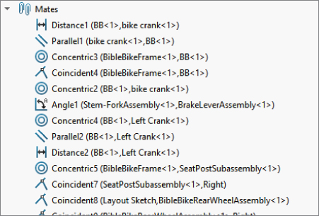
FIGURE 21.1 All the mates in an assembly are shown in the Mates folder at the bottom of the assembly FeatureManager.
Listing Mates in the Mates Folder
The Mates folder can contain other folders that also contain mates to help you organize them. The mates can be renamed, reordered, deleted, suppressed, and edited from this list. By default, the mates are listed in the order in which they were created, and the name of each mate is followed by the names of the parts or assembly features between which the mate was made.
Mates can fail, have warning markers, or be suppressed like other features inside parts. A red octagon with an X in it means that the mate does not meet the geometric conditions. A yellow triangle with an exclamation point means that the mate is in conflict with another mate. Grayed-out mates are suppressed. A small (f) means a mate is suppressed because its part is fixed. A concentric mate with the center filled in means that rotation is locked for that mate. Figure 21.2 shows examples of these errors.
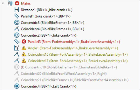
FIGURE 21.2 Know the difference between a warning and an error.
You can see from the mates in the list that there is one error and some warnings. Other mates are also in conflict, and this is one of the biggest difficulties when troubleshooting mates in an assembly. Although several mates are in conflict, only one mate may be causing the problem. A good general rule is to troubleshoot the list of mates from the bottom to the top. This is based on the expectation that more recently added mates are the ones causing trouble. The MateXpert, which is discussed later in this chapter, is a good tool for troubleshooting mates.
Listing Mates Under the Component
Mates are also listed under the component in the FeatureManager. These are the same mates as those listed in the Mates folder at the bottom; however, under the component, only the mates relating to that particular component are listed. Figure 21.3 shows mates listed in this way.

FIGURE 21.3 Mates are also listed in a folder under the component and in breadcrumbs.
This is a very convenient way to list the mates, making them easy to find and nicely organized. One of the drawbacks of listing them this way is that when a mate is causing an error, the error shows up in the Mates folder at the bottom of the FeatureManager, and an error flag appears on each of the parts containing the bad mate.
If you're a fan of using the Breadcrumb display, mates are listed in that as well, with a list of mate symbols showing the state of each mate.
Additionally, subassemblies have mate folders of their own, and parts from the subassembly can be mated to parts or features in the top-level assembly. Ideally, you should mate only a limited number of parts between a subassembly and the upper level, but this is not always possible.
Displaying Mates Instead of Features
Another method of displaying mates under the components enables you to see the mates of more parts at once. In the previous method shown in Figure 21.3, the mates were shown along with the features of the part.
To show the mates associated with each part without the features, right-click the top-level assembly, select Tree Display, and then select View Mates And Dependencies. This option is shown in Figure 21.4.
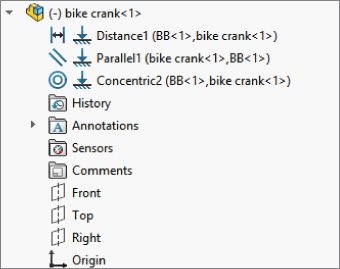
FIGURE 21.4 Displaying the mates without part features
Notice that you can still access the features if you want. They are in a collapsed folder at the bottom of the list of mates. This is a more convenient option for looking at the mates of several parts at one time.
Working with the View Mates Tool
 As its name implies, View Mates is a special tool just for viewing mates. You can access it from the RMB menu when you select a single assembly component (part or subassembly) or multiple assembly components. Figure 21.5 shows the View Mates window when the frame and stem-fork subassembly are selected in the bike assembly located in the materials available for download from the Wiley website.
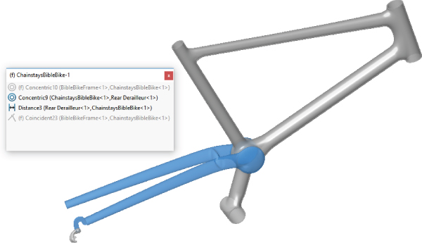
FIGURE 21.5 The View Mates window shows the mates for selected components.
 The icon shown to the left of Distance1 in Figure 21.4 indicates that mate is in the “path to ground,” which means that it is part of the link from the part that is either fixed or mated to assembly planes to outlying parts that depend on other parts for their location. The Path to Ground parts are always listed at the top of the View Mates window. The rest of the mates in the window are all from the parts that are selected.
The parts displayed in blue in the graphics window are the parts mated together from the components selected (the entire fork subassembly is not shown, just the stem part that is actually mated to the frame). As you select mates in the View Mates window, SolidWorks highlights the faces or edges involved, as well as mate names in the graphics window.
View Mates is a useful tool for investigating mating relationships between parts, especially in assemblies that have evolved over time or assemblies that someone else built and that you must understand well enough to work with.
Using the View Mate Errors Window
The View Mate Errors window looks identical to the View Mate window, but it shows only mates that have error or warning flags. It shows all the mates with errors in the entire top-level assembly, not just for the selected component. The View Mate Errors window is available only from the RMB menu and only on components where there are mate errors. It is available only for single selections, never for multiple components. Figure 21.6 shows this window.
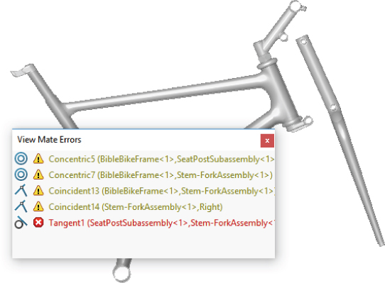
FIGURE 21.6 Using the View Mate Errors window to troubleshoot mate problems
Using the MateXpert
The MateXpert tool helps you troubleshoot assembly problems. You can access the MateXpert by right-clicking a mate with an error, or you can access it from the Tools menu. Don't confuse the MateXpert with the AssemblyXpert; the MateXpert doesn't have an icon, and it deals only with mates.
This example intentionally creates a problem in the bike assembly, so you can see how the MateXpert deals with issues that arise. The problem created here is the same as the one earlier in this chapter, which forced the seat post to be concentric with the stem. After clicking the Diagnose button in the MateXpert, you will see the result shown in Figure 21.7.

FIGURE 21.7 Using the MateXpert to diagnose problems
The MateXpert returns one possible problem in the Analyze Problem panel of the PropertyManager. In this case, the only mate in the assembly that is causing trouble is Tangent1; the rest of the mates display the yellow warning triangle. Notice at the bottom that SolidWorks correctly identifies the one red marker mate as a mate that is not satisfied.
This tool returns lots of information; you may need to sort through it to find the most relevant. When troubleshooting assemblies, you should use whatever set of tools you feel give you the best information for fixing the problem. If you are working through a tangle of mate errors, you may want to use other troubleshooting methods before you rely too heavily on the MateXpert—or you may want to give the MateXpert a glance to see if it points out something you missed before you try a more robust method.
Editing Mates
You can edit mates using the same Mate PropertyManager that you used to create the mates. You access this PropertyManager by right-clicking a mate and selecting Edit Feature from the menu. You can also select multiple mates. Using Edit Feature causes the list of selected mates to show in the Mates window of the Mate PropertyManager. Move from editing one mate to another by just selecting another mate in the window. The Mate PropertyManager for an existing mate is shown in Figure 21.8.
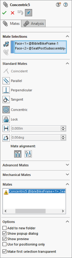
FIGURE 21.8 Editing a mate with the original Mate PropertyManager
One of the advantages of using this method to edit mates is that you can change the type of mate simply by selecting it in the PropertyManager. This is different from features such as the Fillet. After you select a fillet type and create the feature with Fillet, you cannot edit it later and change the type of fillet.
If you want to replace the mated entities, you can delete the one you want to change from the Mate Selections selection box and choose a new one. You can even select an entity from a different part if necessary.
 Another feature for replacing mate entities that is more tailored to the specific task is the Replace Mate Entities tool. You can also find this in the RMB menu for a mate (as well as in the LMB menu, but you must be able to recognize it by its icon or its tooltip). Figure 21.9 shows where you can access both the Edit Feature and the Replace Mate Entities tools from the RMB menu.
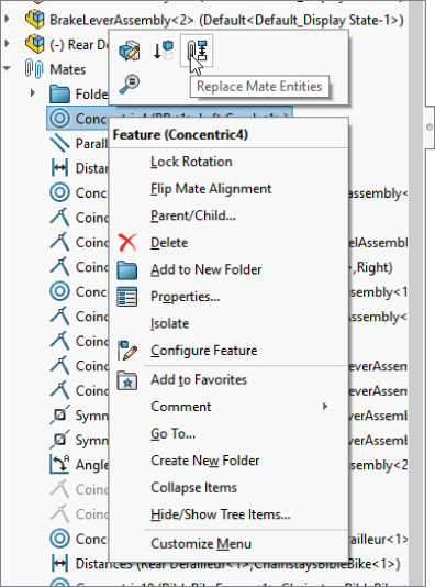
FIGURE 21.9 Accessing the Edit Feature and the Replace Mate Entities from the RMB menu
Selecting Replace Mate Entities displays a PropertyManager called Mated Entities. This interface shows which entities from which parts are used together in the mate. To replace an entity, select it from the Mate Entities selection box; it will appear in the small selection box below. Then simply select the new entity.
When you open this PropertyManager, the Isolate toolbar will also automatically appear. Isolate is a tool that hides parts that are not involved in the current operation. The Mated Entities PropertyManager and the Isolate toolbar are shown in Figure 21.10.
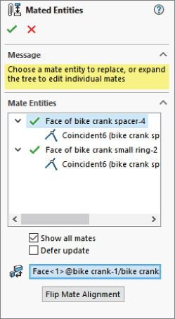
FIGURE 21.10 Changing mated entities using the Mated Entities PropertyManager and the Isolate toolbar
One of the nice features of the Replace Mate Entities tool is that you can select multiple mates before activating the tool from the RMB menu, and all the mate entities will appear in the PropertyManager. This makes changing several mates in one step relatively easy.
You can also select multiple mates to edit in this way using the Mate PropertyManager. The multiple-selected mates will appear in the Mates panel toward the bottom of the PropertyManager (refer to Figure 21.8 where the Concentric 5 mate is shown).
Editing File Management Issues
File management in SolidWorks assemblies requires a certain amount of attention. You must be careful when changing filenames and locations, and you must use the correct tools, or SolidWorks may lose track of where to find necessary data. The best tools to use for SolidWorks file management are, of course, PDM (product data management) tools such as PDM Standard and PDM Professional. After that, SolidWorks and SolidWorks Explorer are good tools for users who don't have access to PDM tools, but these tools require more expertise to keep the references intact.
Using Save Options and Pack And Go
 When making changes to the files involved in SolidWorks assemblies, understanding the Save options will serve you well. Whenever you want to change a name, change a location, or make a copy of a particular SolidWorks document, you should use some combination of the Save, Save As, and Save As Copy tools, as well as Pack And Go. (The icon to the left is shown in the File menu, but the icon shown on the Pack And Go window header is different).
 The Save command displays only a dialog box the first time you save a document. If you are saving an assembly with virtual components, it may ask you to save the assembly with a name in addition to asking you to name and save virtual components externally. Typically, Save isn't an option for anything other than initially placing and naming your files.
 Save As is the tool to use when you want to save the current document to a new name. When you do this, SolidWorks leaves the last saved version of the previous part behind, and going forward, the new name and location you used in Save As will be the one that remains in the assembly.
For example, if you have Assembly 1 and it's made up of Part 1 and Part 2, and these files are already saved to your local hard drive, but you want to rename Part 1 as 875003 base structure.sldprt, then you can use the Save As command to do this. First, you must have the assembly and parts open. Then you can open Part 1 in its own window and use Save As from there. You will get a dialog that helps you sort out what you want to happen, as shown in Figure 21.11. This is one case where you really shouldn't click the Don't Show Again box.
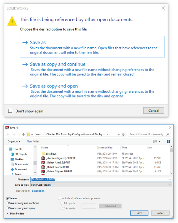
FIGURE 21.11 The options you get before the Save As dialog appears
You can also rename parts in the FeatureManager, but you must set a Tools ➢ Options setting first. Go to the FeatureManager page in System Options and make sure the setting called “Allow component files to be renamed from FeatureManager tree” is on. Then to rename, just right-click on the component and select Rename.
If you make the name change using Windows Explorer, SolidWorks won't know anything about the name change, and the next time you open the assembly, it will tell you it can't find Part 1.sldprt and will ask you to find it.
The More Options section in the Save As With References dialog box enables you to add a prefix or suffix, as well as to use a simple Find/Replace function to rename files in the list. Remember that this makes a copy of the assembly and all the parts with new names or locations.
SolidWorks users frequently use the Pack And Go tool to make a copy of an entire assembly in a new location or to a zip file used to transfer an assembly with all parts to someone who does not have access to the local network. Pack And Go has all the functionality of Save As With References, as well as some additional options. You can also replace files, include drawings and simulation results, and get a quick summary on the number of parts, assemblies, and drawings that are being included. If you aren't using a formal PDM application, Pack And Go can at least serve as a main copy, archive, and renaming utility. The Pack And Go window is shown in Figure 21.12.
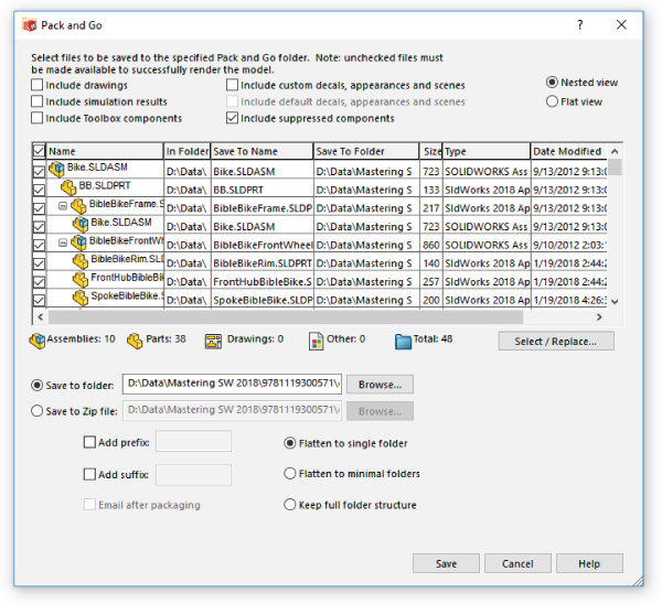
FIGURE 21.12 Pack And Go contains most of your file management needs outside of PDM.
Replacing Components
Following the philosophy that “delete is not an editing method,” SolidWorks includes a tool to replace components that is an improvement over the less graceful delete-and-add technique. When you delete a component, you lose lots of information that you could otherwise keep. Whether you delete a sketch line, a mate, or a part in an assembly, deleting more than doubles the work you have to do. You have to do lots of repair work after you make a deletion. The deeper into a design you are, the more data you lose when you delete something from it. Each piece of information in SolidWorks has some other piece of information attached to it. That associativity is supposed to help rather than hinder you. Learning to use the tools in the way you were meant to use them is one way to improve your efficiency with the software—so you work with the software rather than against it.
 The Replace Components tool is available from the RMB menu of any top-level component in the assembly (not components in subassemblies), although you may have to expand a truncated RMB menu to see it (click the double arrow at the bottom of the RMB menu). Figure 21.13 shows the PropertyManager for the Replace command.
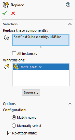
FIGURE 21.13 Replacing a component in an assembly with another component
The All Instances option is an important one. Sometimes, you need to replace only one instance of a particular component with some other part. The All Instances option makes it easy and convenient to replace just what you need.
Other important options have to do with configurations and mates. If the replacement part will use the same configuration name as the original part, you can use the Match Name option. If not, you can use the Manually Select option.
Reattaching mates can be tricky. The more similar parts are in their topology (general layout of model faces), the more likely the automatic reattachment of mates will work. If the mates cannot be reattached automatically, you will be presented with the interface shown in Figure 21.14. This interface shows each of the mates that cannot be reattached automatically, with a small window showing the equivalent face on the old part. It asks you to select a face on the new part that matches the highlighted face on the old part to repair each mate.
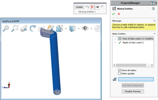
FIGURE 21.14 Reattaching mates by selecting indicated faces on the replacement part
This is a fairly easy process, and it's certainly better than deleting the original part, reinserting the part, and re-creating mates.
Forming and Dissolving Subassemblies
When you initially create an assembly, you may not always know exactly how you want to organize it. Assemblies can serve many purposes, such as for motion, analysis, rendering, assembly instructions, inspection, or a BOM. The structure of each type of assembly with subassemblies might be very different. Therefore, SolidWorks must be flexible in allowing you to change the structure on the fly, again without the wasted effort of deleting and re-creating data.
To create a new subassembly within an existing top-level assembly, select a set of components through appropriate selection methods (advanced select, Ctrl+select, window select, and so on), and then right-click and select Form New Subassembly Here. When the new subassembly is first created, SolidWorks just moves the selected components into the subassembly without any fanfare. The new subassembly is created as a virtual component, so it's just saved within the top-level assembly. If you want to immediately save the new subassembly (named in a format similar to [Assem1^Bike], where Bike is the name of the top-level assembly), right-click the new assembly and select Save Assembly (In External File) from the menu.
USING TREEHOUSE
SolidWorks Treehouse is a tool installed with SolidWorks that you can access through the Windows Start menu, under SolidWorks Tools. It enables you to establish the basic assembly structure of a product including subassemblies, parts, and even drawings. You can use any templates available to your SolidWorks installation to establish the structure, name the files, add configurations, establish custom properties, and save them to a location where individual SolidWorks users can begin working on the detailed geometrical data to go into the file. You can even add existing files if you are reusing data or part of the design is already created when you start mapping the structure.
Treehouse enables you to have a CAD manager establish the structure, an intern add custom properties, engineers or designers create the detailed design, and then drafters create 2D drawings. A sample structure is shown in a Treehouse window in Figure 21.15.
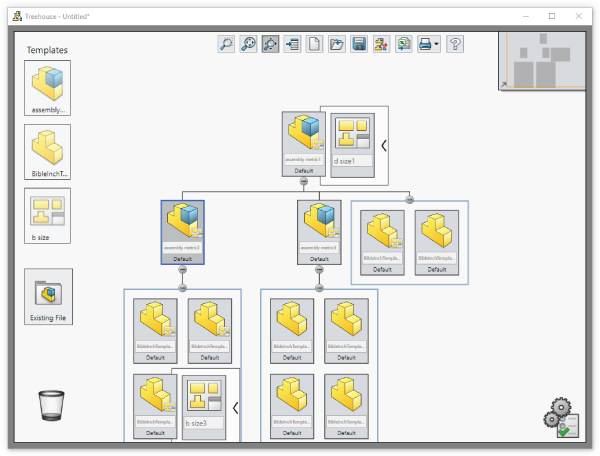
FIGURE 21.15 Using Treehouse to establish a product assembly structure
You can also edit existing assemblies by dragging the assembly file into the Treehouse window. You can add an existing subassembly to an existing top-level assembly by dragging a file from Windows Explorer onto the assembly in Treehouse.
MOVING PARTS IN AND OUT OF SUBASSEMBLIES
Back in the SolidWorks interface, without Treehouse, if you have an existing subassembly, and you want to add to it or remove parts from it, you can drag the component name in the FeatureManager to accomplish this. To drag a part into the subassembly, drag the filename onto the name of the subassembly. You will see the special cursor shown in Figure 21.16. Be sure to pay attention to the text tips being displayed, especially if you're not familiar with the icons.
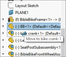
FIGURE 21.16 Adding the BB part to the subassembly Bike Crank
In the example shown in Figure 21.16, the Bottom Bracket part (BB) is being added to the subassembly Bike Crank.
If you want to move a part out of a subassembly into an upper-level assembly, you have to drag the filename from its spot in the subassembly onto the name of the top-level assembly. If you just drag the part above the subassembly, SolidWorks might think you are trying to reorder the display of the name within the assembly FeatureManager. Remember that different symbols exist for moving parts up or down the subassembly hierarchy and reordering parts in the FeatureManager. Undo works for this type of assembly operation.
MOVING MATES FROM AN ASSEMBLY TO A SUBASSEMBLY
Sometimes when you move a part into or out of an assembly, SolidWorks requires that you move mates or destroy certain in-context relationships. If SolidWorks displays a message that it must move mates to another level or break some external references, you must read the message carefully and try to determine whether you can accept the conditions mentioned in the message. You may not be able to easily undo some actions after they are complete. A typical message is shown in Figure 21.17. Losing all the in-context relations in a particular sketch could mean lots of repair work, so you must consider these things carefully.
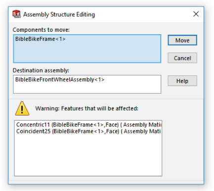
FIGURE 21.17 Read warning boxes when they are displayed; they could be important.
When a mate is moved from a top-level assembly to a subassembly, the mate is no longer solved in the top level, which means you may not be able to use Dynamic Assembly Motion on the parts you just moved from the top level to the subassembly level. You may need to employ a flexible subassembly, which solves the subassembly's mates in the top level. The drawback of this technique is that more mates to solve means more time to rebuild the assembly document and, therefore, a slower working environment. Assembly editing actions often have consequences that you may not anticipate, so be sure to pay attention to warnings from the SolidWorks software.
Evaluating Assemblies
Evaluation tools help you to gain a better understanding of what your starting point is so you can be more efficient with your changes. In the sections that follow, you will learn some new ways to look at and evaluate your SolidWorks assemblies.
Using the Performance Evaluation Tool
The SolidWorks Performance Evaluation tool is described in Chapter 12, “Editing, Evaluating, and Troubleshooting,” but it's reviewed here as well to keep related information together. Performance Evaluation is an informational tool that offers statistics about how many parts, subassemblies, lightweight parts, and so on are in the assembly. It also offers some advice about assembly performance and various settings. Figure 21.18 shows the Performance Evaluation window.
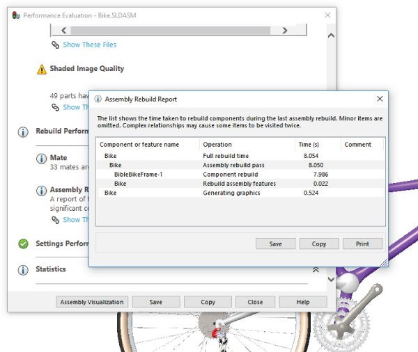
FIGURE 21.18 Using the Performance Evaluation tool to gain information and important statistics about your assembly
Identifying FeatureManager Symbols
You may be wondering what certain rarely seen symbols in the FeatureManager signify. This list includes some of the ones that users often ask about.
 Flexible subassembly
 Lightweight (blue feather)
 Out-of-date lightweight (red feather)
- Path to ground is a mate that is between the part and the fully defined part
 Part made in the academic version of the software
 Toolbox part
Following are some additional symbols in the FeatureManager that are part of the text name.
- (f) This indicates the part is Fixed. The opposite of Fixed is Float.
- (-) This indicates the part is underdefined, that there are not enough mates to lock its position.
- (+) This indicates the part location is overdefined. Overdefined parts typically must have one or more mates removed. This is a situation you should fix in any case.
- -> This indicates an External Reference to a file outside of the current document.
- -> ? This indicates an Out of Context reference, which means it isn't currently loaded in memory.
- -> * This means the External Reference is Locked. You can unlock locked references.
- -> x This means the External Reference is Broken. You cannot repair broken external references.
Using the Isolate Function
Isolate is a tool that enables you to display only selected components. If you right-click a subassembly and select Isolate, you can have it set so that all the other parts are shown as wireframe, transparent, or hidden. This is a nice method to draw attention to a couple of parts or a subassembly while still being able to see the rest of the assembly for reference.
Figure 21.19 shows the Isolate tool in use. To activate Isolate, right-click a part or a selection of parts and click Isolate in the menu.

FIGURE 21.19 Using Isolate in an assembly
When you use Isolate, the small toolbar shown in Figure 21.19 appears and gives you the option to show the rest of the parts in the assembly in one of three modes: Wireframe, Transparent, or Hidden. As long as you have the part or parts isolated, the Isolate toolbar will remain on the screen.
The Save icon on the Isolate toolbar enables you to save the current display as a Display State. This lets you get back to that particular combination of display settings for parts. To return to the previous display, click the Exit Isolate button.
If you want to show another component while in Isolate mode, right-click and select Show Hidden Components, then select the one you want to show, and exit the Show dialog. The Isolate display will be updated to show this newly selected component.
Using Reload
 For people who try things that don't always work out, Reload is one of the most useful commands in SolidWorks. It acts as a shortcut for exiting the current document without saving and then reopening. Reload is available for parts and assemblies, but not for drawings. You can find Reload in the File menu or add it to your toolbars from the Standard category in Tools ➢ Customize ➢ Commands.
Figure 21.20 shows the dialog box that appears when you invoke the Reload command. Notice that this dialog box gives you the option to load Read Only if available, and it includes other file management options that you need to be aware of, especially if you are working on an assembly with other SolidWorks users.
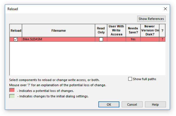
FIGURE 21.20 Reloading an assembly to discard changes
Reload is very handy when you make a change to your part or assembly that you don't want to keep, but you cannot use the Undo command to get rid of it. Reload is useful if you are trying out a technique and don't want to save the results. Just be careful that you don't wind up discarding work that you should keep. Save often.
 A command that you can use in conjunction with Reload is the Check Read-only Files command. This command is available only from a toolbar icon that isn't on the standard toolbar by default, but it's listed in the Tools ➢ Customize ➢ Commands List.
The Check Read-only Files tool checks to see if any read-only files have been changed or if new versions exist in the folder in which you are working. If new versions exist, this tool brings up the Reload tool.
The Bottom Line
You might create your work once in SolidWorks, but you are almost guaranteed to spend more time editing it than you did creating it. Because of that, you need to be even more adept at editing and evaluating your SolidWorks assembly than you are at creating it. SolidWorks has lots of tools to help you do this.
- Master It File management is one skill that doesn't relate to engineering or design, but all CAD operators must be experts. Mismanaging the file can mean you lose a lot of work—or worse yet, by mismanaging, you can create problems with the work that you don't realize until it's too late.
As an exercise, use the SolidWorks Pack And Go to make a zipped copy of an assembly that has in-context references. If possible, take the zip file to another computer with SolidWorks on it and open it up. Check to make sure all of the in-context references are still in-context (and not out of context).
- Master It Sometimes it's easier to look at the big picture and the small detail separately. When you are working on getting Fillet34 to work just right, it's not always a convenient time to also be changing the overall structure of your product's assemblies and subassemblies.
To get some practice, use the SolidWorks Treehouse tool to create the assembly structure for one of your company's products or an automobile if you need a different idea. Get as detailed with it as you can with the time you have available.
- Master It Efficiency is one of the most important qualities of processes, workers, and tools. Use the SolidWorks Performance Evaluation tools to look at the Bike assembly to evaluate which parts are costing you the most to open on your computer. Cost is often measured by rebuild time. Make a set of recommendations for remodeling the bike so that the design costs are lower.