Chapter 4
Creating Simple Parts and Drawings
Good modeling practice is based on robust design intent. This just means that you should try to build parts that can adapt easily to changes. This section of the book begins with things you need to know in order to make good models—models that react predictably in drawings and that update properly with changes. A robust design intent will make downstream operations easier.
Creating simple parts will help you understand the techniques used in more complex modeling projects. Learning on simple tools and then expanding your skills will help you understand best-practice issues, which will make you a better contributor to a team environment.
Discovering Design Intent
By knowing the right information about the part's function before you start modeling or designing, you can create a model that will be easier to edit, easier to properly place into an assembly, easier to detail in drawings, and easier for other SolidWorks users to understand when someone else has to work on your models. Design intent is a statement of how the part functions, the major features of the part, and how the model reacts to modeling changes.
It may help if you try to put the design intent into words to help you focus on what is important in the design. An example of a statement of design intent is “This part is symmetric about two planes, is used to support a 1.00 inch (diametral pitch) diameter shaft with a constant downward load of 150 pounds using a bronze bushing, and is bolted to a plate below it.” This does not give you enough information to design the part, but it does give you information about two surfaces that are important (a hole for the bushing and the bottom that touches the mounting plate), as well as some general size and load requirements.
Using Symmetry
Symmetry is an important aspect of design intent. Taking advantage of symmetry can significantly reduce the time needed to model the part. Symmetry can exist on several levels:
- Sketch symmetry
- Individual feature symmetry
- Whole-part symmetry
- Axial symmetry (a revolved part)
- “Almost” symmetry (the whole part is symmetrical, except for a few features)
- Left and right opposite hand (symmetrical) versions of the part
- Assembly symmetry
Determining Primary or Functional Features
This is probably the most important information to know. Primary or functional features include how the part mounts or connects to other parts, motion that it needs to accommodate, and additional structure to support loads.
Often, it is a good idea to create a special sketch as the first feature in the part that lays out the functional features. This could be as simple as a straight line to denote the bottom and a circle to represent the position and size of a mating part, or as complex as full outlines of parts and features from all three standard planes. This technique is called creating a layout sketch, and it is an important technique in both simple and complex parts. You can use layout sketches for anything from simply drawing a size-reference bounding box to creating the one point of reference for all sketched features in the part. You can use multiple layout sketches if a single sketch on one plane is not sufficient.
Predicting Change
When the marketing department gets out of a meeting at 4:45 p.m., what changes do you need to be prepared for so that you can still be out the door by 5:00 p.m.? No one expects you to be able to tell the future, but you do need to model in such a way that your model easily adapts to future changes. As you gain experience with the software and engineering design processes, keep this idea in mind: you will develop some instincts for the type of modeling that you do.
I've talked a lot about what success looks like with a good design intent model, but let's talk a little bit about failure. Failure will turn out to be more motivating in practice. When design intent fails, you get a feature tree full of errors, and you have to go through each feature, investigate what's wrong, and then fix it. The failures are generally due to errors in the parent/child dependencies following the original change. Fixing errors like this can take up much more time than creating a model in the first place. This is, in essence, the big weakness of history-based modeling. There are a few ways to solve it:
- Be really careful. When this method fails, it is mostly due to the fact that you can't predict the future. (How will change happen?)
- Use a method like Resilient Modeling. This is a structured method where you keep track of the parent/child connections, and only start new sketches on reference geometry with a direct link back to something that will not change (origin or base planes).
- Use a method other than history-based design. This would require a different software package, such as Solid Edge. SolidWorks, in fact, cannot do what is known as “direct modeling,” although the company will tell you otherwise.
I discuss this issue again in Chapter 12, “Editing, Evaluating, and Troubleshooting.”
Creating a Simple Part
Chapter 2, “Navigating the SolidWorks Interface,” introduced the tools and features you will use to create simple parts, and this chapter teaches you how to string the simple features together intelligently. In this section, I'll show you how to build the simple part shown in Figure 4.1. Although the shape is simple, the techniques used and discussed here are applicable to a wide variety of real-world parts. The discussion on how to model the part contains information on some of the topics you must understand in order to do the work.
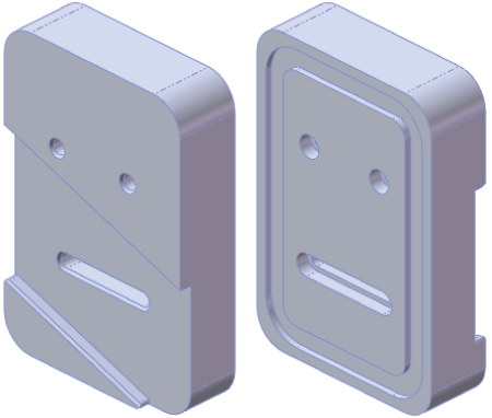
FIGURE 4.1 A simple machined part
Deciding Where to Start
Deciding where to start can be more difficult than it sounds, especially for new users. For this reason, I'll go through some sample parts and discuss possible starting points. Figure 4.2 shows the first part. For reference, all of these parts can be found www.wiley.com/go/mastersolid.
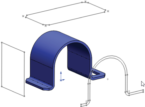
FIGURE 4.2 Which starting sketch is the best?
As you decide how to model geometry in SolidWorks, you should be thinking of a 2D shape and a process. You typically create prismatic shapes by using an Extrude feature and round shapes by using a Revolve feature. Features can also add material (boss) or remove material (cut). Obviously, your first feature must add material.
If you look at the 3D geometry and see it as a series of 2D drawing views arranged in 3D space (as shown in Figure 4.2), you are on your way to deciding where to start.
The part in Figure 4.2 has flat and round faces, but if you examine it, you can create the overall shape using a single extrude. The best option in this case would be to start with a sketch like the one in the lower-right corner and extrude it. This is a good beginning. Although you can make the same part starting from any of the three sketches, the one in the lower-right corner gets you closest to the final shape.
Also realize that you don't need to make all the geometry in a single feature. It is often best to use multiple features for elements such as holes, fillets, chamfers, and other groups of geometry that can be separated out from the main shape.
You might look at the part and see many ways to create it, but the most straightforward way is to extrude the U shape, a rectangular cutout, and four chamfers, as shown in Figure 4.3.
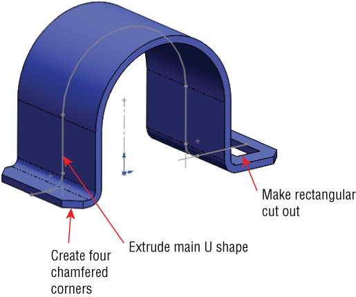
FIGURE 4.3 Breaking down the features in this part
Notice where the part is placed in relation to the origin. Different people might do this differently, and the same person might even do it differently depending on the function of the part. In this case, the origin is aligned with the center of the round shape and at the bottom of the flat face. The placement of the origin suggests that this part sits on the flat face of another part and may hold a cylindrical face of another part.
If you open the part from www.wiley.com/go/mastersolid, you will notice that the origin is also placed in the middle of the extrusion depth. This suggests that the part is symmetrical from front to back.
If you are new to 3D modeling, this might be too much to take in all at once, but you should try to keep the ideas presented here in mind as you work through your first several parts and when you examine SolidWorks parts made by more-experienced users.
Figure 4.4 shows another part with other features. Again, you can choose from several ways to make this part.
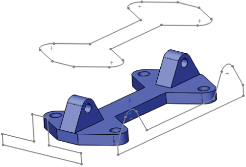
FIGURE 4.4 Identify the best starting point for this part.
In this case, the best option is to use the one on top. (The other two profiles would add geometry that you would have to remove later.) Notice that the holes in the part are not represented in any of the profiles. This is because holes are often added as separate features later. This gives you control over whether the holes are there or not, as well as the size and placement of the holes.
Returning to the part in Figure 4.1, it should be clear enough that this part would be best started from a rectangle, although the rectangle could come from any of the three directions. I personally try to use the biggest sketch that will create a solid that requires the fewest number of additional features. The first feature that you create should also be positioned relative to the origin. Whether a corner of a rectangle is coincident to the origin, the rectangle is centered on the origin, or dimensions are used to stand the rectangle off from the origin at some distance, you need to lock the first feature to the origin with every part you build.
Many people ask how to move the origin, and this is perhaps one of the first things you need to understand about working in SolidWorks. You don't move the origin in SolidWorks. You move everything else in relation to the origin. If you have a part built with the origin in a certain place and want to move it, depending on how the part was built, this might be a very big job. If every feature was created dimensioned from the origin, you will have to move every feature. If features were created dimensioned from an edge of the first feature, you only need to move the first feature. It is also possible to move the entire body, but that is a more complex operation that will be addressed later.
When working with a simple part, the entire part can sometimes be described as rectangular or cylindrical. In cases like these, it is easy to know where to start: You simply draw a rectangle or a circle, respectively. On complex parts, it may not be obvious where to start, and the overall part cannot be said to have any simple shape. In cases like these, it may be best to select the (or a) prominent feature, mounting location, functional shape, or focus of the mechanism. For example, if you were to design an automobile, what would you designate as the 0,0,0 origin? The ground might be a reasonable location, as would the plane of the centers of the wheels. The end of the crankshaft in the engine is often used as the assembly origin in automotive modeling. As long as everyone working on the project agrees, many different reference points could work. With that in mind, it seems logical to start the rectangular part by sketching a rectangle. Select the Top plane, and sketch a centerpoint rectangle centered on the part origin.
Building in Symmetry
Your next decision is about part symmetry. The part in Figure 4.1 is not completely symmetrical. Modeling a quarter of it and mirroring the entire model twice is not the most effective technique. Instead, you should build the complete part around the origin and mirror individual features as appropriate. To start this type of symmetry, you need to sketch a rectangle centered on the origin. Again, to some extent, this is personal judgment.
Sketch a center rectangle where the first point, the centerpoint, is created at the origin. Drag or click the second point (one of the corners) to an approximate size. This creates symmetry in both directions. You can use additional construction geometry and sketch relations to make the rectangle symmetrical side-to-side only.
 Beginning with the rectangle you sketched in the preceding section, apply one horizontal dimension by clicking the Smart Dimension tool on a single horizontal line, placing the horizontal dimension (4.00 inches), and clicking a vertical line, placing the vertical dimension (6.00 inches). The sketch is fully defined at this point because both the size and position of the rectangle have been established. Figure 4.5 shows the sketch at this point.
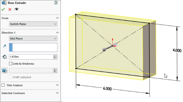
FIGURE 4.5 Sketch and dimension a center rectangle.
Making It Solid
The Extrude feature is one of the staples of SolidWorks modeling. Depending on the type of modeling you do, the Extrude feature may be one of your main tools. This section describes some of the available Extrude options.
EXTRUDING FROM A SELECTION
The From panel establishes where the Extrude feature starts. By default, SolidWorks extrudes from the sketch plane. These other options are available:
- Surface/Face/Plane: The extrusion begins from a surface body, a face of a solid, or a reference plane as shown in Figure 4.6. Surface features are discussed in detail in Chapter 32, “Working with Surfaces.”
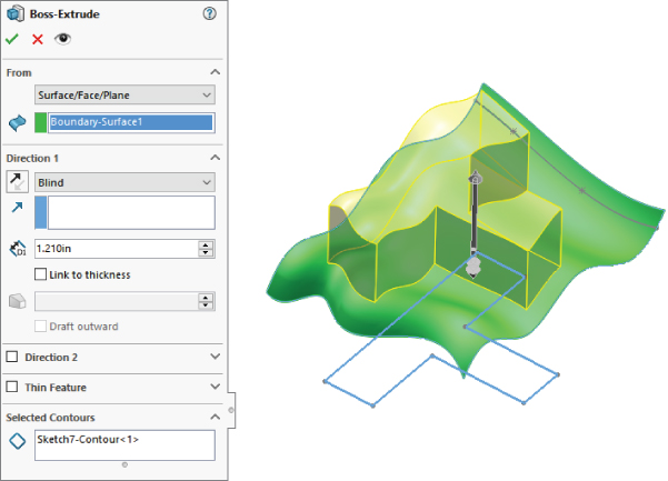
FIGURE 4.6 Extruding from a surface
- Vertex: The distance from the sketch plane to the selected vertex is treated as an offset distance.
- Offset: You can enter an explicit offset distance, and you can change the direction of the offset.
ENDING AN EXTRUSION
Following is a brief description of each of the available end conditions for the Extrude feature:
- Blind: In this case, Blind means an explicit distance. The term is usually used in conjunction with holes of a specific depth, although here it is associated with a boss rather than a hole.
- Up To Vertex: In effect, Up To Vertex works just like the Blind end condition, except that the distance is parametrically controlled by a model vertex, edge, or sketch point.
- Up To Surface: Up To Surface could probably be better named Up To Face, because the end does not necessarily have to be an actual surface feature or body. This end condition may display a warning if the projection of the sketch onto the selected face extends beyond the boundary of the face. In that case, it is advisable to knit several faces together into a surface body and to use the Up To Body end condition.
- Offset From Surface: By default, Offset From Surface extrudes until it reaches a specified distance from a selected surface. There are two methods for determining the type of offset and one for determining direction.
- The default offset method behaves as if the selected surface were offset radially, so that a surface with a 4-inch radius and a 1-inch offset would give a curvature on the end of the extrude of a 3-inch radius (Figure 4.7).
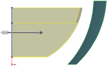
FIGURE 4.7 Offset From Surface using the default
- The second method, called Translate Surface, behaves as if the surface were moved by the offset distance (Figure 4.8).
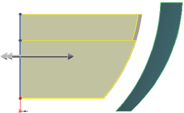
FIGURE 4.8 Offset From Surface using Translate Surface options
- Reverse Offset refers to specifying whether the offset stops short of the selected face (Figure 4.9 top) or goes past it (Figure 4.9 bottom).
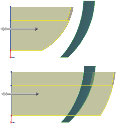
FIGURE 4.9 The Reverse Offset option
- The default offset method behaves as if the selected surface were offset radially, so that a surface with a 4-inch radius and a 1-inch offset would give a curvature on the end of the extrude of a 3-inch radius (Figure 4.7).
- Up To Body: The Up To Body end condition is very useful in many situations, especially when you receive the error message, “The end face cannot terminate the extrusion,” from the Up To Surface end condition.
- Mid Plane: The Mid Plane end condition eliminates the Direction 2 options and divides the extrude distance equally in both directions. For example, if you specify a 1.00-inch Mid Plane, SolidWorks extrudes .50 inches in one direction and .50 inches in the other direction. This is a useful option for ensuring symmetry in a direction normal to the sketch plane.
- Through All: The Through All end condition is available only when solid geometry already exists in the part. When used for an extruded boss (which adds material), it extrudes to the distance of the farthest point of the solid model in a direction perpendicular to the sketch plane. When used for a cut, it simply cuts through everything.
- Up To Next: Up To Next extrudes the feature until it runs into a solid face that completely intercepts the entire sketch profile. If a portion of the sketch hangs over the edge of the face, the extrude feature keeps going until it runs into a condition that matches that description, which may be the outer face of the part in the direction of the extrusion. Figure 4.10 shows the Up To Next end condition used with a Cut extrude.
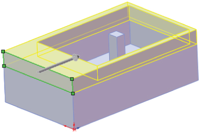
FIGURE 4.10 Up To Next end condition
 By default, the Direction Of Extrusion is normal to the sketch plane, but you can also select a linear entity such as an edge, planar face, face, plane, or axis as the direction. All the end-condition options are still available when you manually define the Direction Of Extrusion as something other than the default.
You can also assign a draft option to an extrusion as it is created, and you can control the draft separately for Direction 1 and Direction 2.
USING THE THIN FEATURE PANEL
The Thin Feature panel is activated by default when you try to extrude an open-loop sketch (a sketch that does not fully enclose an area). The end-condition options remain the same. What changes is that the feature applies a thickness to the sketch elements in the manner of a sheet metal part, thin-walled plastic part, or rib. The Thin Feature panel of the Extrude PropertyManager, along with a representative thin feature extrusion, are shown in Figure 4.11.
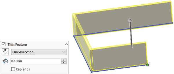
FIGURE 4.11 The Thin Feature panel and a thin feature extrusion
The Cap Ends option is available only when you specify a Thin Feature to be created from a closed-loop sketch. This creates a hollow, solid body in a single step. You can also use Thin Features with cuts, and they are very useful for creating slots or grooves.
USING CONTOUR SELECTION
SolidWorks sketches are easiest to control when the sketches are neat and clean, when nothing overlaps, and when no extra entities exist. However, when you need to use a sketch that does not meet these criteria, you can use contour selection as an alternative method. Contour selection enables you to select areas completely bounded by sketch entities for use with features such as Extrude. For example, you could use a sketch like the number sign (#) where lines do not connect at end points. You can use contour selection to select the box in the center, which is completely bound by sketch elements. Figure 4.12 shows an extrude feature making use of contour selection in a sketch.
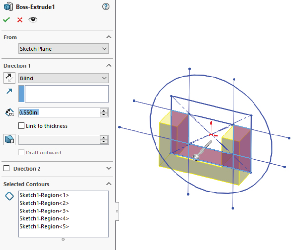
FIGURE 4.12 Using contour selection
Using Instant 3D
 Instant 3D enables you to pull handles to create extrusions and to drag model faces to change the size and location of features. Several feature types enable you to use arrows to adjust elements visually of parametric features and sketches. Figure 4.13 shows the ruler added by Instant 3D shows the arrows added by Instant 3D, which are the handles that you pull on to create a solid from a sketch or edit an existing feature. Notice also that you can make cut features with Instant 3D. In fact, you can change a boss feature into a cut. I'm sure this is a neat sales demo trick, but I'm not aware of any practical application of changing a boss into a cut. Figure 4.13 shows the interface for Instant 3D.
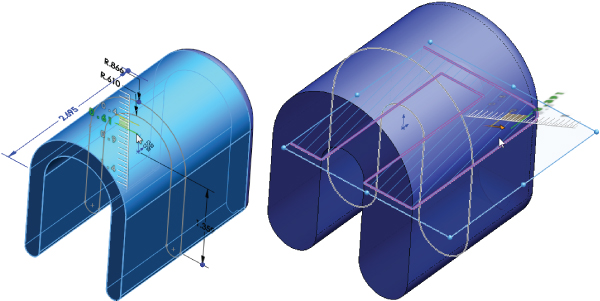
FIGURE 4.13 Using Instant 3D and Live Section
The intent is for this functionality to look and feel like direct modeling, but it is not direct modeling. What you can do is still limited by the features in the history tree and the sketches and dimensions driving the design intent. While this may be handy for making quick visual changes to a model, it is not a great method for precise modeling. Instant 3D can also be an effective tool when used in conjunction with the direct editing type of tools such as Move Face. Instant 3D mimics some of the direct edit type of functionality found in applications such as Solid Edge, SketchUp, and SpaceClaim.
Instant 3D also offers a tool called Live Section, which enables you to section a part with a plane or drag the edges of the section regardless of the features to which the edges belong. To activate Live Section, right-click a plane that intersects the part and select Live Section Plane. Live Section is shown in Figure 4.13.
Chapter 37, “Using Imported Geometry,” discusses the direct edit theme in more detail and revisits the Instant 3D manipulators in that light.
Making the First Extrude Feature
Going back to the sketch in Figure 4.5, I will show you how to continue building the part using the newly learned tools. By centering the sketch on the origin and extruding using a Mid Plane end condition, the initial block is built symmetrically about all three standard planes, with the part origin at the center. In many parts, this is a desirable situation. It enables you to create mirrored features using the standard planes and helps you put parts together later, when parts must be centered and do not have a hard face-to-face connection with other parts. Figure 4.14 shows the initial feature with the standard planes.
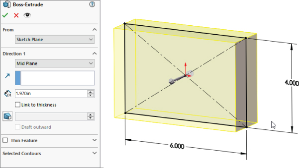
FIGURE 4.14 An initial extruded feature centered on the standard planes
The next modeling step is to create a groove on the back of the part. How is this feature going to be made? You can use several techniques to create this geometry. List as many techniques as you can think of, whether or not you know how to use them.
Figure 4.15 shows multiple methods for creating the groove. From left to right, the methods are a thin feature cut, a swept cut, and a nested-loop sketch.
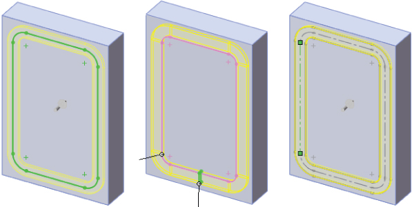
FIGURE 4.15 Methods for creating the groove
With a thin feature cut (shown on the left), you sketch the centerline of the groove and in the Cut-Extrude feature, select the Thin Feature option and assign a width and depth. The option on the right is what is called a nested loop, because it has a loop around the outside of the slot and another around the inside. Only the material between the loops is cut away. The method in the center is a sweep where the cross section of the slot is swept around a path to make the cut.
Another potential option could include a large pocket being cut out, with a boss adding material back in the middle. Each option is appropriate for a specific situation. The thin feature cut is probably the fastest to create, but also the least commonly used technique for a feature of this type. (Many users are not even aware of the thin feature unless they attended specific training or read about it in some of my other books.) Most users tend to use the nested-loop option (one loop inside another) because it enables you to specify geometry more directly, as opposed to specifying the geometry indirectly using the combination sketch and feature settings.
CONTROLLING RELATIVE SIZE OR DIRECT DIMENSIONS
You can control the size of the groove as an offset from the edges of the existing part, or you can drive the dimensions independently. Again, this depends on the type of changes you anticipate. If the groove will always depend on the outer size of the part, the decision is easy—go with the offset from the outside edges. If the groove changes independently from the part, you need to re-create dimensions and relations within the sketch to reflect a different design intent.
The decision of how to control the size of the slot is something I've been putting in the context of design intent, but there is another way of looking at it. Some SolidWorks users, like me, are focused on the 3D model. Many users, however, need to focus on the 2D drawing. If that’s your situation, the decision of how to control the 3D model comes down to what dimensions you want on the 2D drawing. You can take the dimensions from the 3D model and put them directly onto the 2D drawing. If you can do this, it saves you a lot of time. Sometimes, though, the way you create a 3D part is going to be different from how you want to show that part on your drawings. Both methods work. You have to decide how you want to create your parts and how you want to create your drawings.
SolidWorks includes tools for Model-Based Definition (MBD). This is a method where you document the 3D part separate from a 2D drawing. Chapter 41, “Facilities Design Tools,” covers MBD methods in detail, and drawings start in Chapter 24, “Automating Drawings: The Basics.”
CREATING THE OFFSET
You need to consider one more thing before you create the groove sketch. What should you use to create the offset—the actual block edges or the original sketch? The answer to this is a Best Practice issue.
Creating a Simple Assembly
An assembly is a special document type in SolidWorks that allows you to position multiple parts with respect to one another using geometrical mate relationships (such as coincident and concentric) or distance relationships (such as dimensions). The simple assemblies you begin creating here start with a single part that is located with respect to the assembly's origin and standard planes. This is very much like orienting the first sketch of a part to the part's origin.
Parts can be added to the assembly in a number of ways and mated together using reference geometry or faces. It is best if you can use reference geometry, because items like planes and axes tend to be more stable than edges and faces. If you make a change later that removes a face that an assembly mate depends on, that mate fails or does something unexpected.
SolidWorks assembly documents can become extremely complex, with patterns, layouts, in-context, virtual parts, subassemblies, flexible subassemblies, configurations, assembly features, exploded views, in-context features, special Toolbox features, and an assortment of other assembly-only tools available. For the purposes of this chapter, we'll just talk about putting parts together with mates.
When creating an assembly, give careful thought to the selection of the first part. The first part or component of an assembly should always be the key component. In an assembly for a bicycle, the frame would be added first and locked in place using the assembly planes. Similarly, an assembly of an engine would be started with the block, where the block is fixed at the assembly origin.
Like other document types, SolidWorks assemblies start from templates. Before you get started making lots of assemblies, you should make sure you have at least one custom template that you intend to use. Special settings common for assembly templates are units, plane names, drafting standard, custom properties, and other items.
Assemblies have a FeatureManager arrangement of their own. In the assembly FeatureManager, you will find parts and subassemblies, special folders for mates, component patterns, assembly features, Toolbox parts and features, and other assembly-specific items.
Creating the Assembly
 To get started with an assembly, click New, find an assembly template, and double-click it. The settings that come up in the PropertyManager will be the topic of later chapters, starting with Chapter 13, “Building Efficient Assemblies.” You can insert any of the currently open parts or assemblies shown in the Browse window by double-clicking the filename and then clicking in the graphics window to place the part or assembly (Figure 4.16).
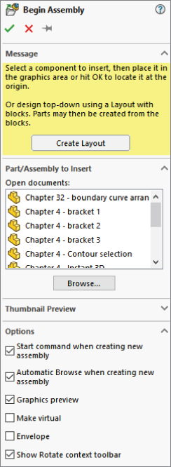
FIGURE 4.16 Creating a new assembly
Notice that the assembly has some folders and reference geometry just like part documents. As you add parts to the assembly, they will be listed in the FeatureManager. Very large assemblies require some special techniques to manage all the data, but for now we are starting simple.
Populating the Assembly
You can use one of several methods for putting a part into an assembly:
- Click Make Assembly from Part/Assembly from the Title Bar toolbar.
- Choose Insert ➢ Component.
- Drag the part from another SolidWorks window.
- Drag the part from Windows Explorer.
- Use the Library in the Task pane.
- Use the Begin Assembly PropertyManager.
- Ctrl+drag to make a copy; Ctrl+C and Ctrl+V to copy and paste parts.
The first part you put into an assembly is always automatically fixed, meaning it does not move. Any other parts you put in have no constraints or mates, unless you add them using Smart Mates or Mate References, as explained in more detail in Chapter 14, “Getting More from Mates.”
Examining Mates
Mates work very much like sketch relations, but they work in 3D space, and they relate edges, faces, vertices, or different types of reference geometry to one another. They do this in order to position and orient parts with respect to one another, but also to allow for motion when a part is dragged with the cursor. Common mates are coincident and concentric—again, just like sketch relations.
Mates are not just for positioning parts, but are also used to establish design intent in the assembly.
Figure 4.17 shows the assembly FeatureManager with several components and some mates.
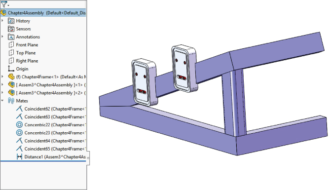
FIGURE 4.17 A simple assembly
Creating a Simple Drawing
CAD salesmen have been telling us for 30 years that 2D paper drawings are going away. 2D drawings may never go away, but what is happening less is drawing three views with individual lines and arcs. Although AutoCAD is still a popular product, it is tedious for view creation.
Drawings in SolidWorks are really just automated snapshots of the model from various views. Any change to the model automatically updates all the views. You can make section views, auxiliary views, cutaway views, and other specialized views quickly when you are working from a 3D model. There are some exceptions to the automatic updates, including when models aren't loaded and a setting called Detached Drawings, when they are intentionally not updated.
To create a new drawing, you again start with a drawing template, which contains the document-specific settings such as units, drafting standard, and so on. You also might use a format, which determines the paper size and has the drawing border with the title block and other items. So, the template is the drawing file with overall settings, and the format is the drawing border. Usually, templates are saved with the format within it, so the blank drawing already has a sheet size and a border.
You can make drawings of individual parts or assemblies, and you can make multi-sheet drawings with an assembly on the front and all the detail parts on subsequent sheets. Drawings can also contain tables such as bills of materials, general tables, hole charts, and other types of annotated charts.
You can also make drawing views from simple sketches. This is useful for layouts, schematics, and items that might not have a physical representation.
Figure 4.18 shows a drawing with some simple views, dimensions, and annotations.
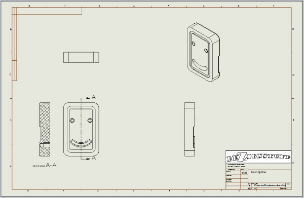
FIGURE 4.18 A simple drawing with views and a title block
Tutorial: Creating a Simple Part
To create the simple part for this chapter from scratch, follow these steps:
- Click the New icon from the Title Bar toolbar, and select an inch part template. (I have included an inch part template with the download materials.)
- Open a sketch on the Front plane.
- Sketch a center rectangle that is 6-inches tall and 4-inches wide, starting from the origin.
- Create an Extrude feature, using the Direction 1 option for Mid Plane, with a depth of 1 inch. Before you accept the Extrude.
To create the groove, follow these steps:
- Open a sketch on a face of the part that’s parallel to the Front plane. To create the offset, expand the Extrude feature by clicking the plus icon (+) next to it in the FeatureManager so you can see the sketch. Regardless of how it displays here, this sketch appears before the extrude in the part history. Right-click the sketch and select Show (or expand the DisplayManager and click the icon in the first column, in the row of the sketch you want to show).
- Right-click the sketch in the graphics window, and click Select Chain. This selects any nonconstruction, end-to-end sketch entities. Click Offset Entities on the Sketch toolbar. Offset to the inside by .400 inches. Apply .500-inch sketch fillets to each of the corners. Exit out of the Fillet command using the green check when the fillets have been applied to the sketch.
- Click Extruded Cut on the Feature toolbar. By default, the extruded cut will cut away everything inside the closed profile of the sketch. Look down the PropertyManager window, and select the check box on the top bar of the Thin Feature panel. Make the cut settings under Direction 1 Blind, .100 inch. The Thin Feature type should be set to Mid Plane with a width of .400 inches. The PropertyManager and graphics window should look like Figure 4.19.
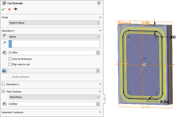
FIGURE 4.19 Creating the groove with a thin feature cut
USING SKETCH TECHNIQUES
Continue with the part from the previous section, and follow these steps:
- Open a new sketch on the large face opposite from the groove. Draw an angled line across the part, as shown in Figure 4.20. Sketch1 should be visible. Click on the Extrude button, and you will be prompted to close the sketch loop. Use the yellow arrow to select the smaller loop.
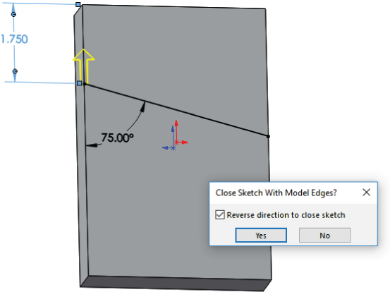
FIGURE 4.20 Closed loop with angled side
- Extrude the sketch to add 0.25-inch material.
- Choose Tools ➢ Options ➢ Sketch and ensure that Prompt To Close Sketch is turned on; then click OK to close the dialog box.
- Open another new sketch on the same face that was used by the last extrusion. Begin drawing another angled line, but before placing the second endpoint, hover the cursor over the angled edge created by the previous feature, and it will highlight orange. Now position the cursor approximately to make a parallel line, and a dotted yellow inference will appear. Draw the angled line using all the automatic relationships that are appropriate, as shown in Figure 4.21.
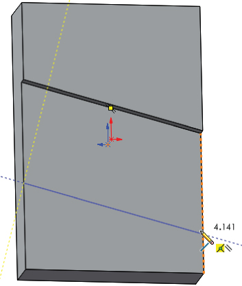
FIGURE 4.21 Using automatic relationships
- Dimension the angled line such that it is 2.025 inches from the first line.
- Use the same technique as in step 1 to make a closed loop, and extrude the feature using the Through All end condition so that it will always match the previous extrusion.
USING THE HOLE WIZARD
The next features that you will apply are a pair of counterbored holes. SolidWorks has a special tool called the Hole Wizard that you can use to create common hole types. The Hole Wizard helps you create standard hole types using standard or custom sizes. You can place holes on any face of a 3D model or constrain them to a single 2D plane or face. A single feature created by the Hole Wizard may create a single hole or multiple holes, and a feature that is not constrained to a single plane can create individual holes originating from multiple faces, nonparallel faces, and even nonplanar faces (holes may go in different directions). All holes in a single feature that you create by using the Hole Wizard must be the same type and size. If you want multiple sizes or types, you must create multiple Hole Wizard features.
To apply counterbored holes to your part, follow these steps:
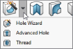 Select the face that the groove feature was created on, and click the Hole Wizard tool on the Features toolbar. Then set the hole to Counterbored, the Standard to ANSI Inch, the type to Socket Head Cap Screw, the size to one-quarter, and the end condition to Through All, as shown in Figure 4.22.
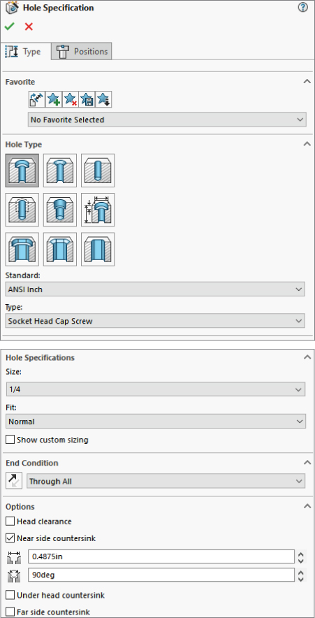
FIGURE 4.22 The Hole Wizard Hole Specification interface
- Click to select the Positions tab at the top of the PropertyManager. This is where you place the centerpoints of the holes using sketch points. It is often useful to create construction geometry to help line up and place the sketch points. Make sure the plane or face that the holes originate from is selected in the Positions tab.
- Draw two colinear construction lines, horizontally across the part, with Coincident relations to each side. Select both lines, and give them an Equal relation. The point of this step is to use parametric relations to evenly space holes across the part without dimensions or equations. Refer to Figure 4.23.
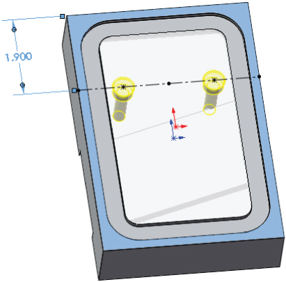
FIGURE 4.23 Placing the centerpoints of holes
 Place sketch points at the midpoint of each of the construction lines. If there is a sketch point other than the two that you want to make into actual holes, delete the extra points. Dimension one of the lines down from the top of the part, as shown in Figure 4.23. All the sketch relation icons are displayed for reference. Click OK to accept the feature after you are happy with all the settings, locations, relations, and dimensions.
CUTTING A SLOT
SolidWorks provides two types of slots: Hole Wizard slots and sketched slots. Fancier slots with the counterbores and countersinks can be made more quickly using the Hole Wizard, but the Hole Wizard is able to create only straight slots. For curved slots, you will need to use the curved slot sketch entity and extrude the sketch as a cut. In this tutorial, we create a curved slot.
To cut slots in your part, follow these steps:
- In this case, use the Centerpoint Arc Slot option. Slots are easiest to create with the Click+click method rather than click-and-drag. Make sure the Sketch 1 under Boss-Extrude 1 is shown. Open a sketch on the face with the groove. Click near where you want the center of the curvature of the slot. Click again for the center of one end; click a third time for the width/end radius. The Slot PropertyManager is shown in Figure 4.24. Create a vertical sketch relation between the origin and the centerpoint of the slot. Make the slot 0.500 inches wide. One way to do this is to place a 0.25 inches radial dimension on one of the end arcs, but a more interesting way to do it is to hold down the Shift key and click both of the big arcs with the Smart Dimension tool. This will give you the difference between the arcs. Continue to dimension as shown in Figure 4.24.
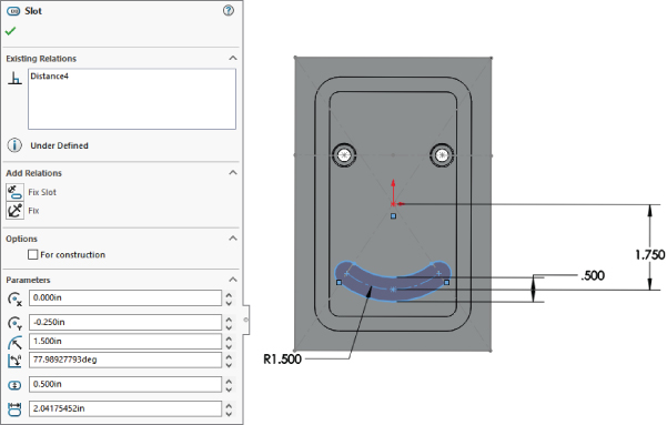
FIGURE 4.24 Creating a slot
- From this sketch, create an extruded cut .75″ deep.
- Open a sketch on the bottom of the previous slot, and offset the slot to the inside by 0.110″. Create a cut using the Through All end condition.
CREATING FILLETS AND CHAMFERS
As mentioned earlier, it is considered a best practice to avoid using sketch fillets when possible and use feature fillets instead. Another best-practice guideline is to put fillets at the bottom of the design tree or at least after all the functional features. You should not dimension sketches to model edges created by fillets unless no better methods are available. Several chapters could be written just about fillet types, techniques, and strategies in SolidWorks. Chapter 7, “Modeling with Primary Features,” deals with more complex fillet types.
To add fillets and chamfers to your part, follow these steps:
- Initiate a Fillet feature, and select the four short edges on the part. Set the radius value to .600 inches. Click OK to accept the Fillet feature. You can use the first icon on the left of the pop-up toolbar, as shown in Figure 4.25, to help you select all four edges around the part quickly.
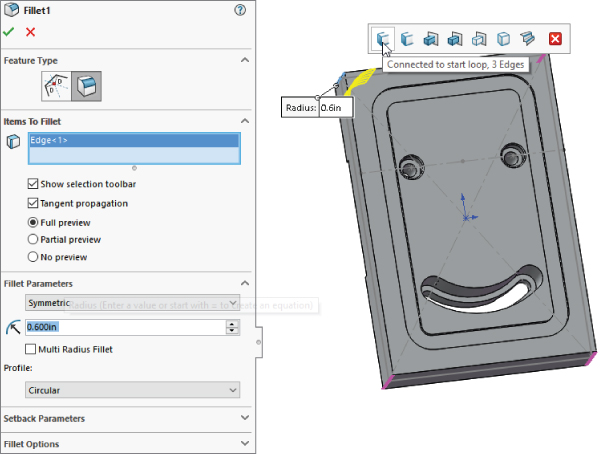
FIGURE 4.25 Selecting edges using the context toolbar
- Apply chamfers to the edges of the angled slot through the part, as indicated in Figure 4.26. Make the chamfers .050 inches by 45 degrees. Chamfers observe many of the same best practices as fillets.
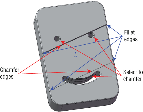
FIGURE 4.26 Edges for fillet and chamfer features
- Select the four edges that are indicated for fillets in Figure 4.26. Apply .050-inch-radius fillets.
- Apply a last set of .050-inch chamfers to the backside of the counterbores and slot.
- Save the part, as
Chapter4SimpleMachinedPartand then close it.
The finished part is simple, but you have learned many useful techniques along the way.
Tutorial: Making a Simple Drawing
In SolidWorks, drawing views are created from the 3D model. Even the most complex section views are almost free, because they are simply projected from the 3D model. When you make changes to the 3D model, all 2D views update. You can handle dimensions in a couple of ways, either using the dimensions that you used to create the model or placing new dimensions on the drawing. (Best practice for modeling is not necessarily the same as best practice for manufacturing drawings.) Model-Based Definition (MBD) is covered in Chapter 40, “Using Model-Based Design.”
To make a simple drawing of a SolidWorks native part, follow these steps:
- Click the New button from the standard toolbar, or choose File ➢ New. From the New SolidWorks Document window, select the Blank Drawing template. The template contains all the document-specific settings.
- After selecting the drawing template, the Sheet Format/Size dialog box appears, as shown in Figure 4.27. This only appears if the format is not already in the template. If your template comes up with the border around it, you can change the border/format by right-clicking on the Sheet1 in the FeatureManager and selecting Properties.
Select the D-Landscape sheet size, as well as the format that automatically associates with that sheet size, and click OK. If the Model View PropertyManager appears, click the red X icon to exit. (If the template you selected already has a format, you can skip this step.)
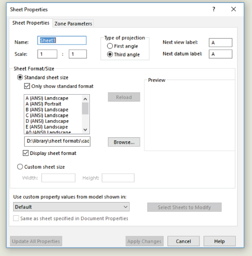
FIGURE 4.27 The Sheet Properties dialog box
- From the Drawings toolbar, click the Standard 3 View button, or through the menus, choose Insert ➢ Drawing View ➢ Standard 3 View. If the Chapter4 SimpleMachinedPart document does not appear in the list box in the PropertyManager, then use the Browse button to select it. When you click the OK button, the three drawing views are created.
- After creating views on the drawing, set up some fields in the format to be filled out automatically when you bring the part into the drawing. Right-click anywhere on the drawing sheet (on the paper) and select Edit Sheet Format.
- Zoom in to the lower-right corner of the drawing. Notice that there are several variables with the format
$PRPSHEET:{Description}. These annotations are linked to custom properties. Some of them have properties with values (such as the Scale note), and some of the properties do not have values (such as the Description).  Add an annotation in the Drawn row, in the Date column. You can add annotations by choosing Insert ➢ Annotations ➢ Note, or by activating the Annotations toolbar in the CommandManager and clicking the Note button. Type today's date as the text of the note.
 Add another note, this time to the Name column. Do not type anything in the note, but click the Link to Properties button in the Note PropertyManager to create a link to a custom property. In the Link To Property dialog box, click the Model In Drawing View Specified option in Sheet Properties. Type user in the drop-down text box below the option. This now accesses a custom property in a part or assembly that is put onto this drawing and called “user,” and it puts the value where the note is placed.
- To return to Edit Sheet mode (out of Edit Format mode), select Edit Sheet from the RMB menu. A little text reminder message appears in the lower-right corner on the status bar to indicate whether you are editing the Sheet or the Format.
- Drawing views can be sized individually or for each sheet. The Sheet Properties dialog box in Figure 4.27 shows the sheet scale. If this is changed, all the views on the sheet that use the sheet scale are updated. If you select a view and activate the Drawing View PropertyManager, you can use the Scale panel to toggle from Use Sheet Scale to Use Custom Scale.
 To create an Isometric view, activate the Drawings toolbar in the CommandManager and click the Projected View button. Then select one of the existing views, and move the cursor at a 45-degree angle. If you cannot place the view where you would like it to go, press the Ctrl key to break the alignment and place the view where you want it.
- You can change the appearance of the drawing view in several ways:
- View ➢ Display ➢ Tangent Edges With Font uses the phantom line type for any edge between tangent faces.
- View ➢ Display ➢ Tangent Edges Removed completely removes any tangent edges. This is not recommended, especially for parts with many filleted edges, because it generally displays just the outline of the part.
- Shaded or Wireframe modes can be used on drawings and are accessed from the View toolbar.
- Perspective views must be saved in the model as a named view and placed in the drawing using the view name.
- RealView drawing views can be placed on the drawing. RealView can be shown in drawings using Shaded or Shaded With Edges and RealView turned on.
- Look at the custom properties that you created in the title block. The date is there because you entered a specific value for it, but the Name field is not filled in. This is because there is no User property in the part. Right-click the part in one of the views, and select Open Part. In the part window, choose File ➢ Properties, and in the Property Name column, type the property name user, with a value of your initials, or however your company identifies people on drawings. The Properties dialog box, also called Summary Information, is shown in part in Figure 4.28.
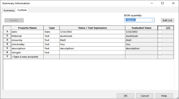
FIGURE 4.28 The Custom Properties entry table
- When you flip back to the drawing (using Ctrl+Tab), the Name column now contains the value of your initials.
 Click the Section View button on the Drawings toolbar. This activates the Section View Assist command so you can place a section line in a view. If you need a cutting line other than a single straight line, the PropertyManager has some options, and other options will be presented after you place the line to allow you to edit it.
- Bring the cursor down to the midpoint of the top edge of the part. When the midpoint is active, you can use the dotted inference lines to ensure that you are lined up with the center. Another option is to manually create sketch relations. Turning on temporary axes displays center marks in the centers of arcs and circles. Figure 4.29 shows the technique with the inference lines being used.
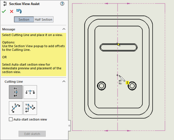
FIGURE 4.29 Creating a section view with the Section View Assist
- As mentioned earlier, you can use two fundamentally different methods for dimensioning drawings:
Model Items imports the dimensions used to build the SolidWorks model and uses them on the drawing. These dimensions are bidirectionally associative, meaning that changing them on the drawing updates the model and changing them on the model updates them in the drawing. On the surface of things, this sounds too good to be true, and it is. The potential problems is that you might not model things the way you would dimension them for the shop. You have to answer several questions for yourself, such as “Do the leader lines go to the right locations or can they be moved?” The dimensions usually come in such a way that they need to be moved around quite a bit.
Reference (driven) Dimensions can be applied to the drawing view directly. These are only associative in one direction, meaning that they measure what is there, but they do not drive the size or position of the geometry. All changes must be made from the model. Again, on the face of things, this appears to be redundant and a waste of time; but in my personal estimation, by the time you finish rearranging dimensions, checking to ensure that you have everything you need, and hiding the extraneous dimensions, you are usually far better off using reference dimensions.
- If you choose to use the Model Items approach, you can do this by choosing Insert ➢ Model Items. Specify whether the dimensions should come from the entire model or just a selected feature. You also need to ask whether the dimensions should come into all views or just the selected one, and whether you want just a certain type of dimension, annotation, or reference geometry.
- After the dimensions are brought in, you need to move some of them from one view to another, which you can do by Shift+dragging the dimension from the old location to the new location. Ctrl+dragging predictably copies the dimension. You can move views by dragging an edge in the view.
The Bottom Line
SolidWorks data is made of parts, assemblies, and drawings. In this chapter, you learned how to create simple examples of each type.
- Master It Create a simple block with holes in it, where every item is dimensioned fully. Use an existing SolidWorks template.
- Master It Create a simple assembly where you bring together some of the parts that you created or worked with in this chapter, and use mates to locate them with respect to one another.
- Master It Create a simple drawing of a single part you made earlier in this chapter. Fill in some custom properties, and make sure the properties propagate over to fill out the title block on the drawing. Use various types of views, annotations, symbols, and dimensions.