Chapter 25
Working with Drawing Views
In SolidWorks drawings, the drawing view is a snapshot of the 3D model from a particular point of view. To change the lines on the view, you have to change the 3D model; you don't just move lines around the view.
SolidWorks automatically maintains the views better than you could do it manually. You don't have to worry about the drawing views being inconsistent or incorrect. All you have to worry about is the 3D model being correct.
SolidWorks can update any type of view from any point of view—even the most complex model or assembly geometry—perfectly.
Creating Common View Types
Chapter 24, “Automating Drawings: The Basics,” discussed predefined views in templates. Predefined views make it faster to automatically create drawings with consistently placed, simple views. However, sometimes you may need to create views on templates that don't have predefined views, or types of view that can't be predefined, or you may need a special arrangement of views. SolidWorks has a good assortment of view types to make practically any type of view you may need.
Using the View Palette
The View palette is shown in Figure 25.1. It's activated automatically if you use the Make Drawing From Part tool, unless the drawing template that you select has predefined views on it.

FIGURE 25.1 The View palette
The View palette contains all the standard named views, the current view of the model, custom named views including saved section views, and any annotation views (views that the model was in when annotations were added to it). You can drag and drop these views on the drawing.
If multiple parts are available, they are listed in the drop-down list at the top of the panel. You can also browse, refresh, or cancel out of the view from this same area.
 To activate the View palette without using the Make Drawing From Part tool, simply create a new drawing document, ensure that the Task pane is available, and click the View Palette tab in the Task pane. Then use the ellipsis button (…) to browse to a part. After you select a part, the palette window will be populated with views of the model. This method has the advantage of enabling you to see the views before you put them down. It does not link views in the same way that the predefined and projected views are linked, however.
Using Model Views
 Model views are one of the few types of views that are not dependent on another view. Everything has to start from somewhere, and most drawings start with either a named or predefined view. A model view starts from a named view in the model.
You can place named views by clicking the Model View button on the Drawings toolbar or by choosing Insert ➢ Drawing View ➢ Model. Using the Model View PropertyManager is a two-step process and is shown in Figure 25.2. In the first step, you select the model, and in the second step, you set the options for the view. Views dragged from the View palette are also model views.
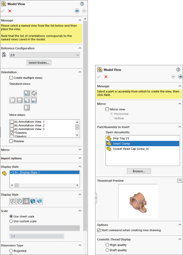
FIGURE 25.2 The Model View PropertyManager
OPEN DOCUMENTS
The large selection box in the Part/Assembly To Insert panel displays any models that are open in SolidWorks at the moment. If the model that you are looking for isn't in the list, you can use the Browse button to look for it.
I typically use the Create Drawing From This Part/Assembly command if the part is open, and if not, I drag and drop the part onto a new drawing created from a template with predefined and projected views on it. This combination saves lots of extra steps.
If you click in the drawing window for some reason (for example, if you are expecting it to simply place a view), a prompt will appear, stating that you have selected a drawing document and that only parts and assemblies can be inserted into drawings.
THUMBNAIL PREVIEW
This is a nice option that shows the part that you selected in the Open Documents window. It's a useful feature, but because it's collapsed by default, it's easy to miss. After it's used the first time, it remembers the expanded setting.
START COMMAND WHEN CREATING NEW DRAWING OPTION
The Start Command When Creating New Drawing option causes this PropertyManager to open immediately when a new drawing is created. If you click in the drawing window, the prompt will appear, telling you that you're not paying attention.
REFERENCE CONFIGURATION
The Reference Configuration list enables you to select which configuration of the part to show in the view. This shows up not only when you create new views, but also in the generic Drawing View PropertyManager that shows up when you select any view.
SELECT BODIES
When a part has multiple bodies, a button called Select Bodies also shows up in this panel. If the part doesn't have multiple bodies, you won't see this button. When you click the button, it will immediately take you to another PropertyManager, the smaller one shown in Figure 25.3 called Drawing View Bodies, where you'll be sent back to the model window to select a body. Clicking the green check mark after selecting a solid body in Drawing View Bodies will then send you back to the drawing to place the view. It won't send you back to the Model View PropertyManager.
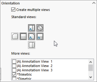
FIGURE 25.3 Placing multiple views
If you click the red X in the Drawing View Bodies PropertyManager, SolidWorks will leave you in the part window, and you will have to press Ctrl+Tab to get back to the drawing window.
COSMETIC THREAD DISPLAY
Make sure you read the names of the settings carefully. The Display Style panel has the same options as the Cosmetic Thread Display options, and they can easily be confused. The distinction between high and draft quality is made for performance reasons. The difference in terms of display is that in High Quality mode, hidden cosmetic threads (cosmetic threads that are behind a face) don't display in Shaded mode.
NUMBER OF VIEWS AND ORIENTATION
To create multiple views, toggle Create Multiple Views in the Orientation panel of the Model View PropertyManager. Next, select all the views from the Standard Views icons that you want to be displayed, including any choices from the More Views list, such as Current Model View and any named or annotation views that exist. These views are indicated on the drawing as boxes (representing view borders), as shown in Figure 25.3.
This is really useful functionality. It makes view selection and placement very easy and is visually clear. Unfortunately, the Single View setting is the default setting, and the PropertyManager does not remember the last setting that was used. Still, the combination of Multiple Views and Orientation is far better, in my opinion, than the View palette.
IMPORT OPTIONS
The Import Options panel is for bringing annotations into the drawing view that is being created. You should find it an advantage, being able to select these items quickly from the PropertyManager while the view is being created.
DISPLAY STATE
On the drawing, you can select the Display State. This is probably meant for situations like using Display States for hide and show operations, but remember that there is much more to Display States than just hide and show. You can also change display styles, colors, and transparency.
DISPLAY STYLE
Display Style is the selection that includes Wireframe, Shaded, Shaded With Edges, and so on. You can set the default Display Style by choosing Tools ➢ Options ➢ System Options ➢ Drawings ➢ Display Style. This panel provides an override for views being placed. This panel also enables you to control High or Draft quality views, which are described later in this chapter.
SCALE
SolidWorks drawings always default to showing views at the overall sheet scale unless the System Option on the Drawings page called Automatically Scale New Drawing Views is selected. If this setting is selected, the sheet scale saved with the drawing template is overridden. For example, a 1:1 sheet scale can be changed automatically by changing the setting to 1:4.
You can change the sheet scale through the Sheet Properties, which were discussed in Chapter 4, “Creating Simple Parts and Drawings.” Controlling views with the sheet scale makes it much easier to change the size of a drawing and to scale all the views together. Individual views can be displayed at the view scale, and detail views are typically created at a different scale automatically. To locate the scale setting, choose Tools ➢ Options ➢ System Options ➢ Drawings ➢ Automatically Scale New Drawing Views. Detail Views, covered later in this chapter, automatically get a note showing the custom scale for the view.
You can automatically add a label or note to an orthogonal drawing view displayed at a scale different from the sheet scale. You access this setting at Tools ➢ Options ➢ Document Properties ➢ Views ➢ Orthographic. Enable the Show label if the view scale differs from the Sheet Scale option, and specify the rest of the settings shown in Figure 25.4 as appropriate.
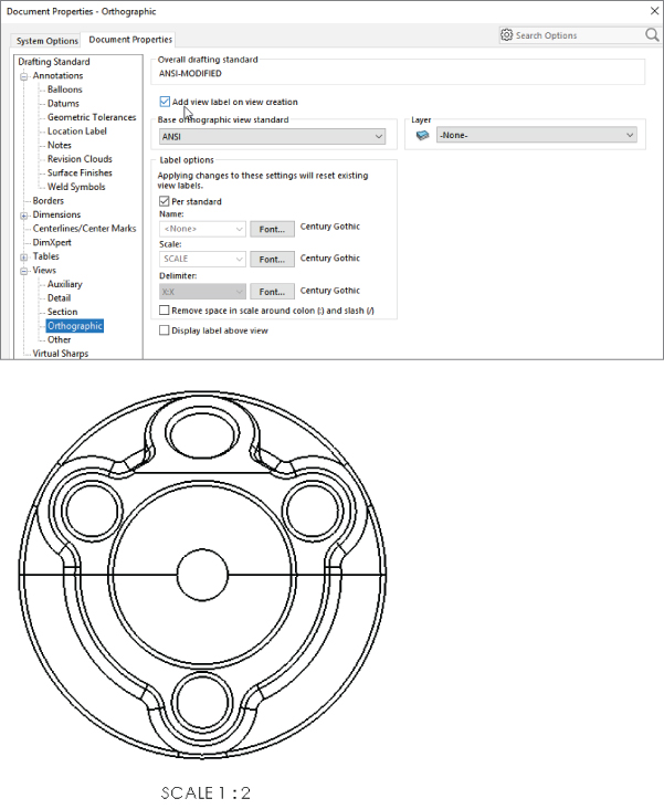
FIGURE 25.4 Displaying a label to show the view scale when it is different from the sheet scale
DIMENSION TYPE
Even in nonorthogonal (isometric) views, true dimensions should be used for most drawing views. Projected dimensions depend on the angle of the edge to the view plane.
Using the Projected View
 The Projected View type simply makes a view that is projected in the direction that you dragged the cursor from the selected view. For example, if you drag at a 45-degree angle, the result is an isometric view. When placing an isometric view that you have created in this way, SolidWorks constrains the new view to a 45-degree-angle line through the origins of the two views. To place the view somewhere other than along this line, press the Ctrl key while placing the view to break the alignment. The PropertyManager for the projected view is shown in Figure 25.5.
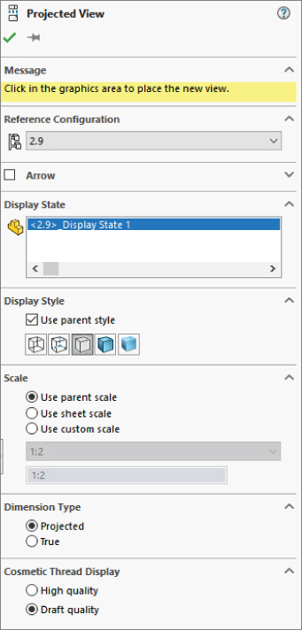
FIGURE 25.5 The Projected View PropertyManager
Be aware that first angle and third angle projections result in views that are opposite from one another. Third angle projection is typically ANSI standard, and first angle projection is typically ISO standard, although you often find third angle projection used in ISO as well.
When you use the pushpin on the Projected View PropertyManager, you can place multiple projected views from the originally selected view or select a new view from which to project views. Display properties and scale of the projected views are taken from the parent view.
Some views require more than one copy of the model to be loaded into RAM at once, such as views with different configurations. These views are considered high cost. Because of the extra RAM requirements, they will slow down the performance of the drawing. Projected views and model views are low cost.
Using Standard 3 View
 You can access the Standard 3 View tool on the Drawings toolbar by choosing Insert ➢ Drawing View ➢ Standard 3 View. This places a front view and projects top and right views for third-angle projection drawings. Figure 25.6 shows the PropertyManager for the Standard 3 View function.
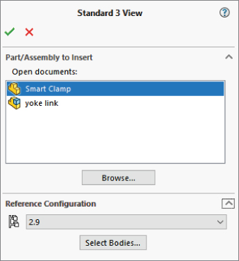
FIGURE 25.6 Standard 3 View PropertyManager
Use the PropertyManager to select open models that you want to place on the drawing. Select configuration and body or bodies to place here as well.
Using Detail View
 You activate the detail view from the Drawings toolbar or by choosing Insert ➢ Drawing View ➢ Detail. Either way, you can use the function in two different ways: one that's fast and easy and the other that gives you more control but isn't quite as fast.
PRE-DRAWING A DETAIL CIRCLE
You can draw the detail “circle” before you initiate the Detail View command. When you pre-draw a detail circle, you must ensure that you're sketching in the view and not on the sheet. To draw in the view, the view must be activated. You can activate a view by clicking in the view or by bringing a sketch cursor inside the boundary of the view. When you activate a view, the status bar in the lower-right corner of the SolidWorks window displays the message “Editing Drawing View,” as shown in Figure 25.7.
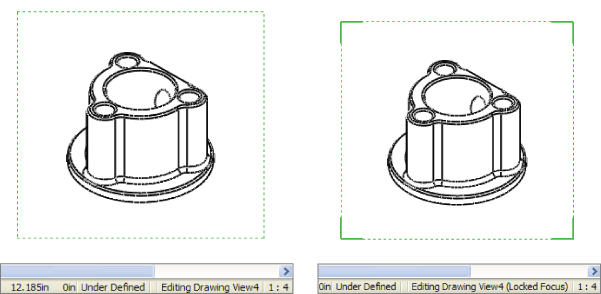
FIGURE 25.7 Activated drawing views
The dotted border in the image to the left shows that the view is selected, and the status bar shows that it's activated. The image to the right with the solid corners indicates that the view has Locked Focus. You can lock focus on a drawing view by double-clicking it or by right-clicking and selecting Lock View Focus from the menu.
If a view isn't activated or the focus isn't locked on the view, then any sketch elements that you draw will be placed on the drawing sheet. While sketching in a drawing view, it's a good practice to watch the status bar.
The point of all this is to sketch a closed loop in the view so it can be used for a detail view. The closed loop can be a circle, ellipse, spline, series of lines, or any other shape, as long as it's a closed loop.
A setting controls how the circle (loop) displays, in particular whether it displays as drawn or as an actual circle. This setting is found in the Detail Circle PropertyManager. If the setting is grayed out, the Style option may be set per standard, and the standard you are using does not allow for noncircular detail circles. You could choose With Leader instead or change the drafting standard you are using. The different results are shown in Figure 25.8.
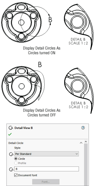
FIGURE 25.8 Drawing a closed loop with the Display Detail Circle As Circles option turned on and turned off
After you create the loop, you can click the Detail View toolbar button and place the view. The view is automatically scaled by the factor set at Tools ➢ Options ➢ Drawings ➢ Detail View Scaling. By default, this scale is set to twice the parent view scale, but you can reset the default to whatever you like.
DRAWING A DETAIL CIRCLE IN-LINE
A faster way to complete the detail view is to simply click the Detail View toolbar button without preselecting or pre-drawing the loop. This activates the Circle sketch tool immediately, which activates the view as soon as you bring the cursor over the view, so that when you draw the circle, it's sure to be in the view rather than on the sheet.
Alternatively, you could swap the Circle tool for an ellipse or a spline; this works just as well, but it offers more flexibility. Regardless of the sketch tool, when you close the loop, SolidWorks prompts you to place the view. The workflow for this in-line method is better than the old-school pre-drawn loop technique.
EDITING A DETAIL VIEW
You can edit a detail view by dragging the circumference of the detail circle to a new diameter, dragging the center of the detail circle to a new location, or selecting Edit Sketch from the Detail Circle right mouse button (RMB) menu. This method enables you to edit sketch relations or otherwise edit the sketch that you used for the detail. When you are finished with the sketch, you can use the Confirmation Corner to click OK.
You can delete detail views by selecting and deleting the detail circle. Deleting the detail circle gives you the option to delete the resulting view as well as the original sketch. Also, deleting the detail view gives you the option to delete the detail circle and the original sketch.
Working with Section Views
 The Section View workflow goes like this:
- Select the Section View tool.
- Select View To Section.
- Select the orientation. Press Tab to cycle through the options.
- Place a section line in the view.
- In the pop-up toolbar, click the green check mark to accept, click the curly arrow to go back a step, or click the X to cancel.
- Place the view.
- Double-click the section line to reverse direction.
Using the Auto-start Section View option enables you to skip the pop-up toolbar step.
Figure 25.9 shows the new Section View PropertyManager as well as the cursor interface. The lines drawn for you automatically are called Section View Assist. You can still draw the lines manually if you find it’s an easier way to get the results you want.
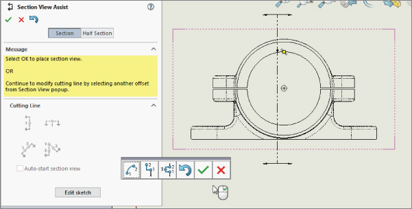
FIGURE 25.9 Using the new Section View tools
You can also use jogged section lines with the new Section tool. If you feel the need to resort to sketching the section line, the Edit Sketch option is available.
The new Section View tool borrows some skills from other areas of the software. First, the Edit Sketch option is borrowed from sheet metal functionality; it's useful if you have created a flange automatically and want to edit it manually. Second, the jogged section works much like explode lines in assemblies.
To create a jogged section, use the Vertical, Horizontal, or Auxiliary section options, as illustrated on the toolbar shown in Figure 25.10.
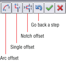
FIGURE 25.10 The pop-up toolbar for creating jogged sections
You can also specify how deep you want the section view to see into the part. In the PropertyManager of the section view, you can set a depth with a number, or you can select a face, edge, or vertex to determine the depth. When you select the check box at the top of the Section Depth panel, a graphic handle becomes available on the drawing view, enabling you to visually drag the depth as well. This functionality is shown in Figure 25.11.
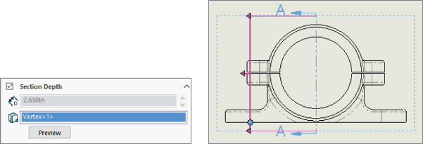
FIGURE 25.11 Setting a depth for a section view
USING A HALF, PARTIAL, AND SLICE SECTIONS
A Half section is a full model view with a portion of it cut away, so it shows the sectioned and unsectioned areas. A Partial section shows only the sectioned area, with any background edges. A Slice section only shows the area that is actually cut, without any other model edges. These section types are demonstrated in Figure 25.12.
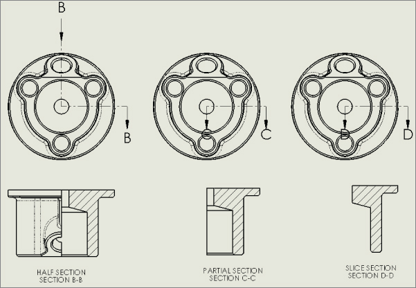
FIGURE 25.12 Comparing Partial and Half sections
To get started with a Partial or Slice section, you can sketch a section line that doesn't go all the way through the model. To start a Half section, use the Section View Assist, as shown in Figure 25.13.
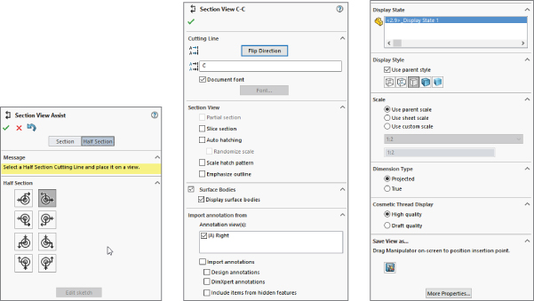
FIGURE 25.13 Section View PropertyManager
USING AN ALIGNED SECTION VIEW
The Aligned section view takes two separate sections at angles to one another and lays them out flat on the page. It is essentially two partial sections that display side by side. You can use the Section View Assist for aligned sections as well, by selecting the Aligned option in the Section View PropertyManager, as shown in Figure 25.14. Click the center of the aligned section to place the cut line in the view. You can select another centerpoint to place the angled line. The second line is vertical by default, but you can place it at any angle you choose as well.

FIGURE 25.14 The Aligned section view
EDITING A SECTION VIEW
Section views are edited in the same way as detail views. You can edit the section lines directly by dragging or by using the section line sketch through the RMB menu. You can click the RMB menu and select the Edit Sketch command to edit sketch relations, or to add to or remove sketch elements from the sketch.
Section views are also deleted in the same way as detail views, with the option to also delete the underlying sketch for the section. When you delete one segment of the section line, the resulting view, as well as the underlying sketch, is also deleted.
Section views are considered high-cost views because the computer must keep in RAM another version of the model including the section cut. However, section views also communicate the relation of the interior of an assembly to the exterior very effectively, so it may be worth the extra performance slow down.
Creating Other View Types
SolidWorks can create almost any type of view you need. You can put shaded, RealView, and transparent views on drawings. You can also put Broken, Broken-Out section, Cropped, alternate position, empty views, and even hand-drawn views.
Using a Crop View
 The crop view is simply a view that looks like a detail view without requiring a parent view. This feature enables you to reduce the number of views on a sheet and save some room. However, a cropped view may be confusing if it isn't clear which area is being detailed in the cropped view.
Unlike detail views, in crop views the closed loop must be sketched in the view before you invoke the command. To make the crop view, draw the closed loop as shown in Figure 25.15 on the left, and then click the Crop View button on the Drawing toolbar or access the command by choosing Insert ➢ Drawing View ➢ Crop.
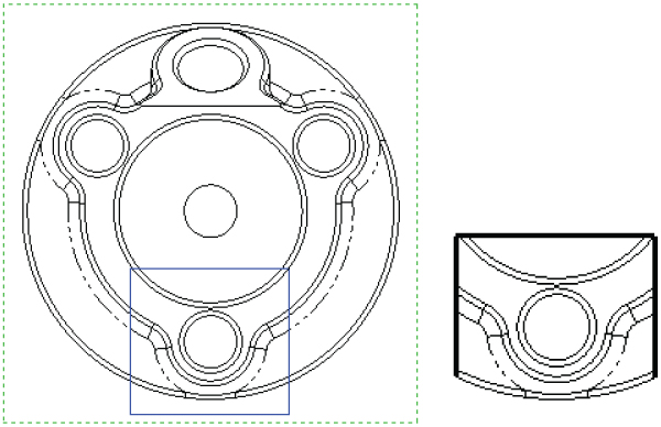
FIGURE 25.15 A sketch loop and a crop view
To edit a crop view, right-click the view, expand the arrow next to Crop View, and select either Edit Crop or Remove Crop. Removing the crop doesn't delete the sketch that was used to create the crop.
Again, crop views are considered low-cost views.
Using a Broken-Out Section View
 The Broken-Out section view is another view type that alters an existing view rather than creating a new view. It also requires a closed-loop sketch. The Broken-Out section view is very useful in assembly views where parts are obscured by other parts—in particular, when a set of parts is inside a housing and you want to show the inside parts without hiding the housing. Of course, you can also use Broken-Out section views on parts with internal detail.
Broken-Out section views act like a cut that's created from the drawing view. Any faces created by the cut are hatched. Figure 25.16 shows a casting part view using a Broken-Out section view. You can create Broken-Out sections on parts or assemblies. You cannot create Broken-Out section views using existing detail, section, or alternate position views.
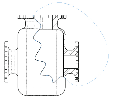
FIGURE 25.16 A Broken-Out section view
Notice that in Figure 25.16 the temporary axes for the flange holes are showing and cannot be turned off. This is probably a display bug left over from SolidWorks 2011.
The hatch pattern is associated with the materials assigned for each part. You can change the hatch scale by double-clicking a hatched region and using the settings in the dialog box shown in Figure 25.17. To change the hatch size, you must deselect the Material Crosshatch option.
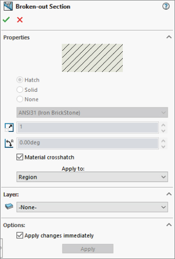
FIGURE 25.17 Changing the hatch pattern on a Broken-Out section
Broken-Out section views require you to specify a depth for the break. You can use an edge selected from a different view or a distance to specify the depth. In the case of the Broken-Out section, the depth is into the screen, while with the regular section, the section depth is measured as a distance perpendicular to the section line.
DRAWING THE CLOSED LOOP
Broken-Out section views are initiated from an existing view either with or without a pre-drawn closed loop. If the loop is pre-drawn, you must select it before clicking the Broken-Out Section toolbar button on the Drawings toolbar or accessing the command by choosing Insert ➢ Drawing View ➢ Broken-Out Section.
If the view has no pre-drawn, preselected loop, then initiating the function activates the Spline sketch tool. It isn't necessary to use a spline as the closed loop for this view type, but Broken-Out section views are traditionally created with a freehand sort of boundary, even when drawn manually.
If the loop is closed in an uninterrupted workflow, then after the last spline point is drawn, joining the spline back to itself, the Section Scope dialog box will appear. This will enable you to select any parts that are not to be sectioned if an assembly is in the sectioned view. It's customary to avoid sectioning shafts, screws, or other cylindrical components. Figure 25.18 shows the use of the Section Scope to exclude the two shafts in the assembly from the section cut.
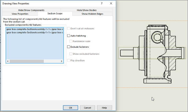
FIGURE 25.18 Using the Section Scope
The recommended workflow is to initiate the function from the toolbar, use the spline to create the closed loop, and to not pre-draw a loop. This makes everything flow more smoothly, and you will create the view surprisingly quickly. If you must use a sketch tool other than the spline, then you must pre-draw it. Even if you simply change sketch tools when the Broken-Out section view automatically activates the spline, because the workflow has been broken, creating the closed loop won't automatically display the Section Scope interface.
SELECTING THE DEPTH
After you make the Section Scope selections, the next step is to set the depth of the cut. You can do this in several ways. Broken-Out section views are usually applied to the center of a hole if available or in other ways that show the view as cleanly as possible. If you know the depth of the cut that you want to make, you can enter it as a distance value. Of course, that raises the question, “Distance from what?” The answer seems to be, “From the geometry in the view that would come the farthest out of the screen toward the user.” Users most often choose the distance when it doesn't matter exactly how deep the cut goes or exactly where it cuts, but it gives a relative position.
In situations when you want to cut to the center of a particular feature or up to an edge, it's far easier and less bothersome to simply select the geometry from a drawing view. For example, Figure 25.19 shows the PropertyManager interface where the depth of the cut is set. In this example, the edge of the shaft in the view to the right has been selected. This tells SolidWorks that the cut should go to the center of the shaft. Another possibility is to display the temporary axes, as shown in Figure 25.19, and to select an axis through the center of the shaft.
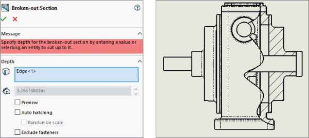
FIGURE 25.19 Setting the depth of the Broken-Out section view
EDITING THE VIEW
At this point, the view is finished. Now you may choose to edit the view in some way, such as by changing the sketch, the depth, the section scope, and so on. Figure 25.20 shows how the Broken-Out section view is positioned in the Drawing FeatureManager. It is listed as a modification to an existing drawing view. The Broken-Out Section RMB menu is also shown. Selecting Edit Definition displays the PropertyManager (refer to Figure 25.19). Selecting Edit Sketch enables you to change the section spline shape. Selecting Properties displays the dialog box shown to the right in Figure 25.20. This contains options for the underlying original view as well as the Broken-Out section modification to the original view. Only the Section Scope tab is added by the Broken-Out section view. The rest of the options are for normal view properties.
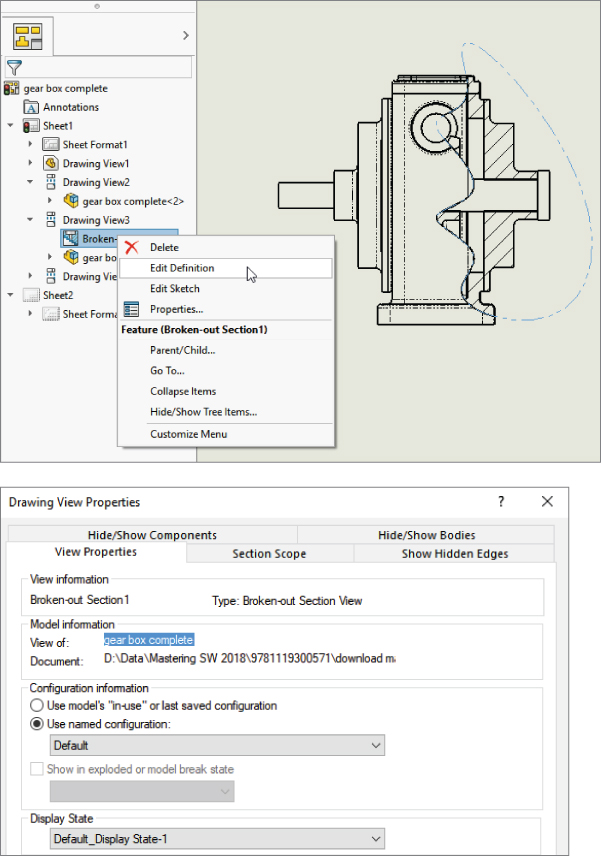
FIGURE 25.20 Editing the Broken-Out section view
Using a Break View
 Break views are typically used to display parts that are very long in one dimension on a drawing in such a way that you can see both ends or other important features. You can break views more than once in the same direction or even in opposite directions. Figure 25.21 shows the full view of a part and a view that was broken twice. Notice that the dimensions are correct, and any dimension that includes a broken length has a special dimension line.
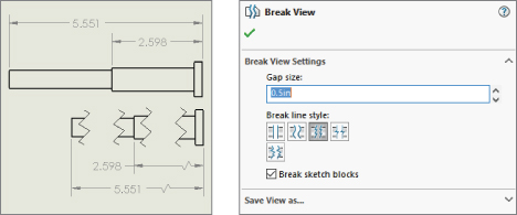
FIGURE 25.21 Dimensions on a break view
To create a break view, click the Break toolbar button on the Drawings toolbar, or choose it at Insert ➢ Drawing View ➢ Break. You need to place break lines in pairs, and you can choose from one of five break symbol styles, as shown in Figure 25.21. You can change the style from the RMB menu or from the PropertyManager.
The Broken View PropertyManager also enables you to set the gap size and the style of the break. The gap refers to the gap between the break lines in the finished broken view. The setting here overrides the default for this view only. The default setting is a template setting found in Tools ➢ Options ➢ Document Properties ➢ Detailing. Other options that you can set in this location are the break line extension (the distance the lines extend past the model edges) and the break line font (on the Line Font page of the Document Properties tab). The setting that enables the broken symbol on a dimension is found on the Dimensions page and is called Show Dimensions As Broken In Broken Views.
You can remove individual breaks in a broken view by selecting one of the break lines and pressing Delete. You can add breaks by applying the Break command and adding more breaks to a view. You can alter breaks by simply dragging the break lines. In past versions, it was possible to get the view very confused by dragging one set of breaks to interfere with another set of breaks. That problem has been fixed by not allowing break lines to be dragged past one another.
Broken views enable you to dimension the break lines themselves so that when the model changes, you can control the location of the break lines relative to part geometry.
Consider using the Unbreak option from the RMB menu to temporarily unbreak a view to make dimensioning more convenient.
If you intend to create two views, one projected from the other, and you intend to break both views, create the first view and break it as desired, and then project the second. The second view will be broken in the same place as the parent view. Any projected child view will be broken in the same place. Conversely, if you create a section view from a broken view, the section view will be broken as well.
Using an Auxiliary View
 An auxiliary view is a view that is projected from a non-orthogonal edge, intended to display edges in true length, without foreshortening. This type of view is often necessary to view features (such as holes drilled at an angle) square on, so they appear circular in the view rather than foreshortened and elliptical. An auxiliary view is shown in Figure 25.22 on the left. If the edge that the view was created from is updated, then the auxiliary view will reorient itself. The image on the right shows an auxiliary view projected from an arbitrarily drawn sketch line. The line or edge used to project an auxiliary view cannot be reselected; however, if a sketch is used to project the view, then the Edit Sketch option is available through the view arrow RMB menu.
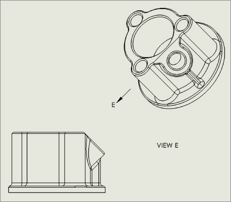
FIGURE 25.22 Two auxiliary views
Using an Alternate Position View
 The alternate position view is available only for views of an assembly and shows the assembly in two different positions (not from different viewpoints, which requires an assembly that moves). This is another view type that doesn't create a new view but alters an existing view. Figure 25.23 shows the PropertyManager interface for the alternate position view, a sample view that it creates, and the way that it's represented in the drawing FeatureManager.
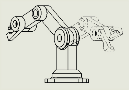
FIGURE 25.23 The alternate position view
To create an alternate position view, ensure that you have an assembly on the active drawing that can have multiple positions, and click the Alternate Position View button from the Drawings toolbar, or choose Insert ➢ Drawing View ➢ Alternate Position and then select the alternate position view.
Next, click in the drawing view to which you want to add the alternate position. The PropertyManager shown in Figure 25.24 prompts you to select an existing configuration for the alternate position or to create a new configuration. If you choose to create a new config, the model window will appear, a new config will be created, and you will be required to reposition the assembly. The alternate position will be shown in a different line font on the same view, from the same orientation as the original.
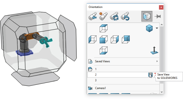
FIGURE 25.24 Using the Saved Views command in the model
To delete an alternate position view, select it in the drawing FeatureManager and press Delete.
Using a Predefined View
 Predefined views are discussed in depth in Chapter 24, “Automating Drawings: The Basics,” and are primarily used as views on drawing templates.
Using an Empty View
 Empty views are just that—empty. The reasons for creating an empty view can include making a view from a sketch, making a schematic from blocks, or combining several elements—such as blocks, sketches, imported drawing geometry, annotations, and symbols—into an entity that can be moved as a single view on a drawing.
Using a Saved View
You can create saved views by orienting the view in the model document and saving the view. Remember that views can be saved in the View Orientation window, which you can access by pressing the spacebar. Saved views are placed on the drawing using the model view functionality.
Saved views are often used with section views, to predefine the view in the model and access it quickly in the drawing.
Although not appropriate for showing dimensions, views using perspective are most useful for pictorial or illustrative views. The only way to get a perspective view on a drawing is to place a saved view in the model with Perspective turned on. You can access the Perspective option by choosing View ➢ Display ➢ Perspective, and you can edit the amount of perspective by choosing View ➢ Modify ➢ Perspective.
Access saved views in the model by pressing the spacebar and using the Saved Views flyout. Create new saved views by clicking on the Save (diskette) symbol next to the numbers under Saved Views, as shown in Figure 25.24.
To use these saved views in the drawing, place a model view on the sheet, and select the name of the saved view from the More Views list on the second page of the PropertyManager, shown in Figure 25.25.
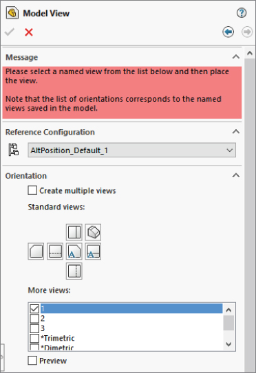
FIGURE 25.25 Placing a saved view using the Model View view type on a drawing
Converting a Drawing View to a Sketch
Right-click anywhere inside a view border and select Convert View To Sketch. When you do this, you will be presented with three options—replace the view with the sketch, replace the view with a block, or insert the view as a block on the drawing sheet. The second two options create the block as a copy. You might want to convert a view to a sketch if you want to make alterations to the appearance of the actual model to represent a process or illustrate something that would be difficult or impossible to model.
Saving a View to DWG/DXF
To save a view to DWG/DXF, select the view so the PropertyManager shows up, and then at the very bottom of the PropertyManager, find the panel called Save View As. This panel enables you to drag a manipulator in the view to establish the insertion point. Then click the Save icon (which looks like a diskette) to save the view as either DXF or DWG. Previously, this was available only for flat pattern views for sheet metal or for entire drawings.
Using a Relative View
 The Relative View PropertyManager enables you to create a view that does not necessarily correspond to any of the standard orthogonal views or named views. Using this type of view is very similar to using the Normal To tool. First, select the face that is to be presented square to the view, and then select the face that represents the top of the view. When this view type is initiated, SolidWorks will open the 3D Model window to allow you to select the faces needed to define the view.
This type of view is particularly useful when a part has a face that's at an odd angle to the standard planes of the part. It's in some ways similar to the auxiliary view, except that in the auxiliary view, you cannot select which face is the top.
The Relative View PropertyManager has a special function that is important for drawings of multibody parts. If both faces used to establish the view are from the same body, then all the rest of the bodies in the part can be hidden with an option in the Relative View PropertyManager, which is shown in Figure 25.26. Multibody modeling is covered in Chapter 31, “Modeling Multibodies.”
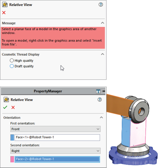
FIGURE 25.26 The Relative View PropertyManager
Using the 3D Drawing View Mode
 The 3D Drawing View mode is not technically a drawing view type. It's a mode that enables you to select faces or edges of the model that may need to be selected for some purpose but cannot be seen from the orientation of the drawing view. You can invoke the 3D Drawing View mode from the 3D Drawing View toolbar button, which is on the View toolbar and can be accessed by choosing View ➢ Modify ➢ 3D Drawing View from the menus.
Ironically, this mode does not work for the relative view, which would be a perfect application for it. Instead, relative view makes you go to the model window. The 3D Drawing View mode is intended for views such as the Broken-Out section view, where a depth must be selected for the cut.
In Figure 25.27, notice the small toolbar above the drawing view. This toolbar is available while the 3D Drawing View mode is turned on. Clicking OK on the small toolbar turns off the mode and returns the view to its previous state.
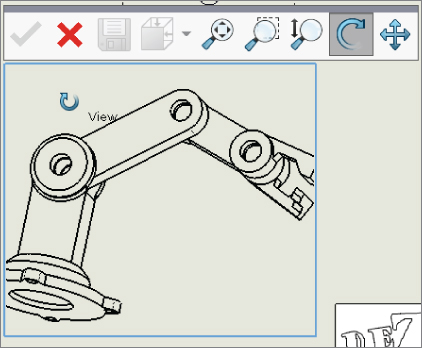
FIGURE 25.27 The 3D Drawing View mode
Changing View Orientation and Alignment
 Although you may have selected the top view, and it displays the correct geometry, you may want to spin the view in the plane of the paper or orient it in a particular way. You can do this using two methods. The easiest way to reorient the view is to use the Rotate View tool on the Heads-Up View toolbar. This rotates the view in the plane of the paper much as it rotates the model in 3D.
Another option is to select an edge in the view and assign the edge to be either a horizontal or vertical edge. Figure 25.28 shows how a view can be reoriented using this tool, which you can locate by choosing Tools ➢ Align Drawing View ➢ Horizontal Edge or Vertical Edge.

FIGURE 25.28 Rotating a drawing view to align an edge
Alignment in the RMB menu refers to alignment of the entire view with other views. Align in the Tools menu refers to aligning annotations. Align Drawing View in the Tools menu is the menu you want, although it does not reference rotating the view.
Another option for view alignment is to align it relative to another view; this involves stacking one view on top of another or placing them side by side. You can do this by selecting the second pair of options in the menu shown in Figure 25.28, Horizontal To Another View and Vertical To Another View. Preselecting a linear edge will activate the Horizontal To Another View and Vertical To Another View options.
Situations may arise where a view is locked into a particular relationship to another view, and you need to disassociate the views. The Break Alignment option, which is grayed out in the menu in Figure 25.28, serves that purpose.
Using Display Options in Views
Some important display options and settings are not listed in Tools ➢ Options menu; they are available only through the menus, and in particular the View menu. You can effectively deal with most items in the View menu by assigning a hotkey that can be toggled on or off. For example, axes and temporary axes are things you often want to be visible when you're sketching something, but not visible when printing a drawing. You can easily assign the display for axes and temporary axes to hotkeys, making them ready at your fingertips. You can assign hotkeys by choosing Tools ➢ Customize ➢ Keyboard.
Using Display States
You can use display states in drawing views, but unless you are only hiding and showing parts with the display states (that is, you are not changing colors or display styles with display states), they have an effect only when a drawing view is set to Shaded Display style. You can control the display states for drawing views in the View PropertyManager. The Drawing View Properties dialog box is shown in Figure 25.29.
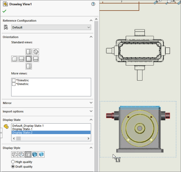
FIGURE 25.29 The View PropertyManager
One of the limitations of the Display States functionality in drawing views is that when wireframe display is used, the drawing edges appear in black rather than using the color settings to show wireframe in the same color as shaded. The necessary color settings are found in two places, and you need to set both. The System Options setting is on the Colors page and is called Use Specified Color For Shaded With Edges Mode. The second setting is in the part Document Properties (not assembly), again on the Colors page, and is called Apply Same Color To Wireframe, HLR (Hidden Lines Removed), And Shaded.
Using Display Styles
The 2D drawing world is becoming less and less black and white, and SolidWorks has the capability to apply shaded views to drawings. This is probably most useful in isometric, perspective, or pictorial views on the drawings. The shading and color may be distracting for dimensioned and detailed views, but it can also be indispensable when you need to show what a part actually looks like in 3D. Not everyone can read engineering prints, and even for those who can, nothing communicates quite like a couple of shaded isometric views.
The more standard 2D drawing display modes are Wireframe, HLR, and HLV (Hidden Lines Visible), which work in the same way as they do in the model environment. Unless you override it on a per-part basis, the Display mode is set for all the components in the view.
SELECTING A COMPONENT LINE FONT
Individual components within an assembly can be shown in different fonts, similar to the display in the alternate position view. You can access this function by right-clicking the component and selecting Component Line Font. Figure 25.30 shows the Component Line Font dialog box, along with a drawing view in which a couple of part line fonts have been changed. The part can be changed only in the view where it was selected, or it can be changed across the board in all views in the active drawing where it appears. This is useful if you want to emphasize or de-emphasize certain parts in the assembly view.
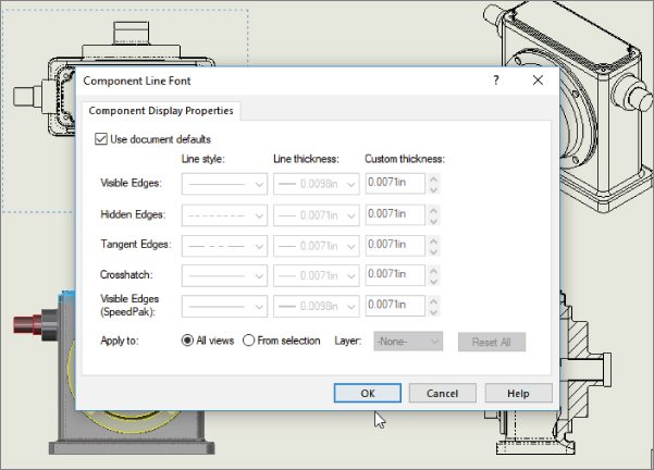
FIGURE 25.30 The Component Line Font dialog box
USING LAYERS
Yes, SolidWorks drawings can use layers. You can place individual parts onto layers, and the layers can have different colors and line fonts. Most entities can be put into layers, including edges, annotations, and sketch items. Hidden layers are often used for reference information or construction entities on a drawing. Figure 25.31 shows the Layers dialog box and the Layers toolbar on a SolidWorks drawing.
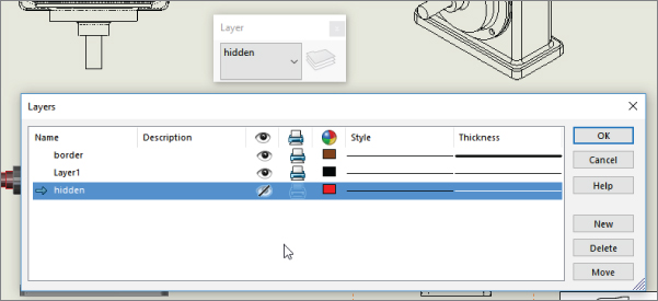
FIGURE 25.31 Using the Layers dialog box in SolidWorks
Working with Tangent Edge Display Options
SolidWorks drawings and models offer some options for displaying tangent edges. Tangent edges are the breaks between faces when the faces are tangent, such as between flat sides of a box and the fillet that comes between them. Many users find it distracting when tangent edges (which in a physical part are not edges at all) are given as much visible weight as the sharp edges of, say, a chamfer. To find the settings, shown in Figure 25.32, choose View ➢ Display or select them from the RMB menu. The Tangent Edges Removed option may be appropriate for parts with few fillets, but it causes a part to look oversimplified and makes details of the shape difficult to distinguish.

FIGURE 25.32 Edge display options
Additional options are available, including applying a color to the tangent edges by choosing Tools ➢ Options ➢ Color list for tangent edge display and the Hide/Show Edges options.
 You can use the Hide/Show Edges tool for specific selected edges, or just click the tool with nothing selected to activate the Hide/Show Edges PropertyManager, shown in Figure 25.33. Hide/Show Edges functionality is available only with high-quality views. View quality is addressed in the next section. Hide/Show Edges is available from the left-click context toolbar, the RMB menu, or the Line Font toolbar.
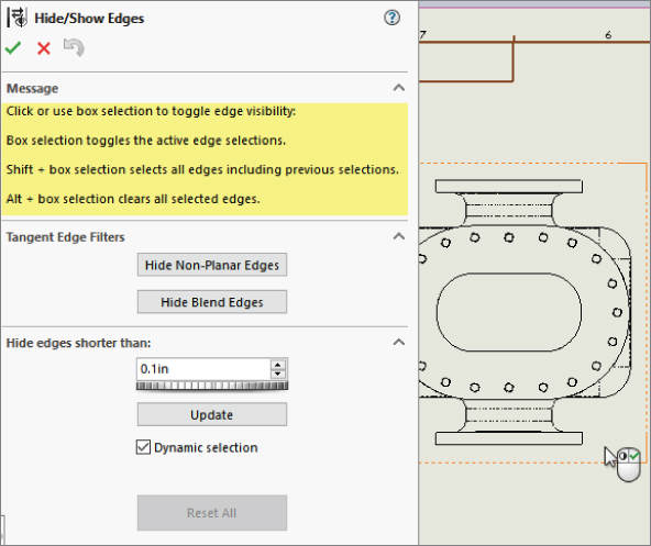
FIGURE 25.33 The Hide/Show Edges PropertyManager offers tangent edge display options.
The PropertyManager indicates that Hide/Show Edges works from a selection, although it has no list box to show the edges selected. The tools offered here may not have a wide general appeal, but they probably will be the most useful to people documenting complex shapes or plastic parts. Hide Non-Planar Edges is meant to simplify the display of complex parts with lots of curvature. Hide Blend Edges limits the filtering to edges with curvature continuity across the edge, which is usually found only in more sophisticated surfaced parts. The Hide Edges Shorter Than option gives you the ability to filter the edge display again. These settings apply only to the current view, not to the entire drawing.
Take note of the options in the Hide/Show Edges PropertyManager message box shown in Figure 25.33:
- Box selection toggles the active edge selections.
- Shift+box selection selects all edges, including previous selections.
- Alt+box selection clears all selected edges.
These mass selection options can be important if you are using a command such as Tangent Edge Filters, Hide Non-Planar Edges, Hide Blend Edges, or Hide Edges Shorter Than A Given Value.
Choosing View Quality Settings
You can choose between two options for the drawing View Quality: High Quality and Draft Quality. The quality you choose influences the performance of the software. Draft Quality views are noticeably rough when viewed closely, but from a distance, they look the way they should.
All views are created as High Quality unless the View Quality setting is overridden. To find this setting, choose Tools ➢ Options ➢ System Options ➢ Drawings ➢ Display Style ➢ Display Quality For New Views. The only other way that you can create Draft Quality views is if you open a drawing from an older version of SolidWorks that used Draft Quality views.
In Figure 25.2 earlier in the chapter, the image to the right shows the Display Style pane. This PropertyManager has been taken from a High Quality view. A Draft Quality view enables you to toggle between Draft Quality and High Quality, as shown in Figure 25.33. This means that you can switch a view from Draft to High, but not from High to Draft. Also notice in Figure 25.29 that the cursor over a Draft Quality view displays a lightning bolt symbol, indicating Draft Quality.
You can access the Cosmetic Thread Display setting in both the Step 1 PropertyManager and the Step 2 PropertyManager. However, you need to be careful not to misread the interface by thinking that either of these interfaces controls the View Quality.
If you are thinking about the performance of a drawing, be aware that Draft Quality views are created from the graphics tessellation or triangle-based display information, while High Quality views are generated directly from the NURBS geometry.
Distinguishing Views from Sheets
It's sometimes difficult for new users to understand the difference between being in a sketch and being out of a sketch, or the difference between editing the sheet as opposed to the sheet format. In the same way, confusion frequently surrounds the difference between sketching in a view and sketching on a sheet. The easiest way to determine if a sketch will be associated with a view or with the drawing sheet is to look at the prompt in the lower-right corner of the SolidWorks window, on the status bar that displays the message Editing Sheet, Editing Sheet Format, or Editing View.
This issue becomes especially important when you want to do something with a sketch entity, but it's grayed out and unavailable. This means that whatever entity is active is not the one that the sketch entity is on. Drawing view borders expand to contain all the sketch entities associated with the view, so if you see a view that's extended on one side, larger than it should be, it could be extended to contain the grayed-out sketch entity. Activate the sheet and the suspected views; when the sketch entity turns from gray to black, you have found the place where it resides.
Tutorial: Working with View Types, Settings, and Options
This tutorial is intended to familiarize you with many of the view types, settings, and options that are involved in creating views. To begin, follow these steps:
- From the download materials, open the part called
Chapter 25 – Tutorial Part.sldprt. - Move the drawing template named
Mastering 2pg B size.drwdot, also found in the download materials, to your Templates folder. If you do not know where your templates are located, choose Tools ➢ Options ➢ System Options ➢ File Locations ➢ Document Templates. - From the window with the open part, click the Make Drawing From Part button on the toolbar. The drawing will be populated with three standard views and an isometric view, as shown in Figure 25.34.
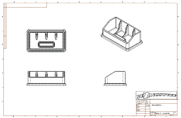
FIGURE 25.34 Using a template with predefined views
- Click the Section View tool on the Drawings toolbar. This will activate the Section View Assist tool.
- In the top view (in the upper-left section of the drawing), place a vertical line that picks up the inference from the origin or an edge midpoint. You may have to run the cursor over the origin to activate the inference lines, as shown in Figure 25.35. After you place the cut line, click the green check on the pop-up toolbar to accept the placement. Place the section view to the right of the parent view. If you cannot see the origin, use the View menu to show it.
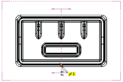
FIGURE 25.35 Creating a section view
To change the letter label on the drawing, click the section line and change the label in the top panel of the Section View PropertyManager.
 Bring the cursor over the corner in the section line until the cursor looks like the image to the left. Double-click the cursor; the section arrows will flip to the other direction, and the drawing view will become cross-hatched. The cross-hatching indicates that the view needs to be updated.
- Press Ctrl+Q; the view will update and remove the cross-hatching.
- Click the section line and press Delete. Answer Yes to the prompt. You may also need to separately delete the sketched section line.
- Create a new section view using a jogged section line, as shown in Figure 25.36. To do this with Section View Assist, activate the Section View tool, select the Vertical option, place the cut line at the origin, select Single Offset in the pop-up toolbar, (as shown in Figure 25.36), click the cut line at the origin, and then pull the jog to the right, (also shown in Figure 25.36).
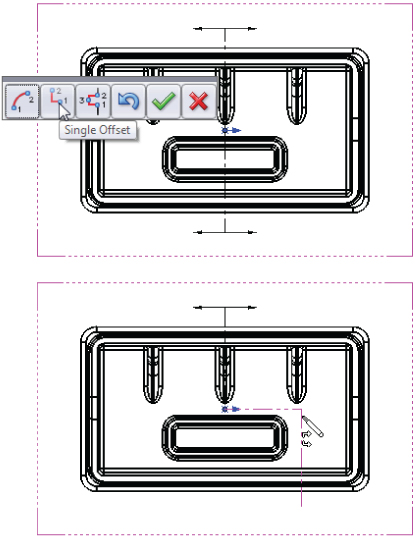
FIGURE 25.36 Creating a jogged section view
- Click the Detail View button on the Drawings toolbar. This will activate the Circle sketch tool.
- Sketch a circle in the front view, located in the lower-left section of the drawing. Try not to pick up any automatic relations to the center of the circle. One way to prevent this is to hold down the Ctrl key when creating the sketch.
- Place the view when the circle is complete. Note that the view was created at a scale of 1:2. The sheet scale is 1:4, so the detail is two times the sheet scale. The detail view is shown in Figure 25.37.
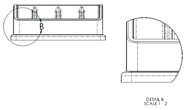
FIGURE 25.37 Creating a detail view
- Drag the circumference of the circle and watch the view dynamically resize.
- Leave the Detail circle selected so the center of the circle is highlighted. Drag the center of the circle around the view. The effect is like moving a magnifying glass over the part. If you drag the center with the Ctrl key pressed, you won't pick up any automatic sketch relations when you drop it somewhere.
- Click the Broken-Out Section View tool on the Drawings toolbar. Draw a spline on the right view similar to the one shown in the left image in Figure 25.38. Use a section depth of 1 inch. Working with splines take a little practice.
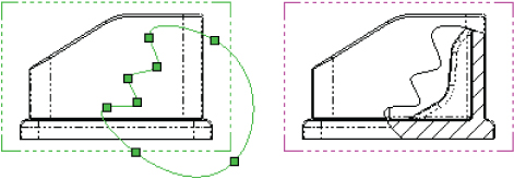
FIGURE 25.38 Creating a Broken-Out section view
- Click inside the view border but outside of the part in the top view (in the upper-left section of the drawing). Press Ctrl+C.
- Click the Add Sheet icon to the right of the Sheet tab in the lower-left corner of the drawing that says Sheet1 and select Add New Sheet. If you used the template provided, a message may appear, saying that SolidWorks cannot find the format. This is because I only supplied the template file, not the format as a separate file. In any case, switch to the B size format and accept.
- Click any spot inside the sheet and press Ctrl+V. SolidWorks will paste the copied view from the other sheet. Delete the section line. You may also need to delete the sketch lines separately.
- Click the Projected View tool from the Drawings toolbar, and then click the pasted view. Practice making a couple of projected views, including dragging one off at a 45-degree angle to make an isometric view. Make sure one of the views is a side view showing the angled edge, as shown in Figure 25.39. After you create the views, click model edges in the views and drag them around to a better location.
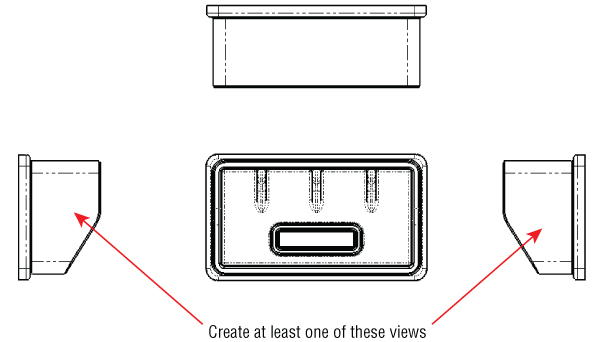
FIGURE 25.39 Projecting views
- Select the angled edge from one of the side views and click the Auxiliary View toolbar button. While placing the view, press and hold the Ctrl key to break the alignment. You can resize the view arrow by selecting the corners and dragging. If you drag the line itself, you can move it between the views. Alternatively, with the view arrow selected and the PropertyManager displayed, you can deselect the green checkmark icon in the Arrow panel at the top of the window to turn off the arrow.
- Create a new drawing from the New dialog box. Select a template without predefined views on it, so the
Inch B Bible Template (no Views).drwdotwill work. If you select a default SolidWorks template, you need to verify that the template uses third angle rather than first angle projection. An easy way to do this is to switch the drafting standard from ISO to ANSI in Tools ➢ Options ➢ Document Properties ➢ Drafting Standard. If the automatic Model View interface appears in the PropertyManager, click the red X icon to cancel out of it. - Expand the Task pane and activate the View palette (the tab that looks like a Drawing icon). Click the ellipsis button (…) and browse for the assembly named
Chapter 25 - SF casting assembly.sldasm. This is shown in Figure 25.40.
FIGURE 25.40 The View palette
- Drag the back view onto the drawing. Notice that when you use this technique, the views do not resize automatically, regardless of the setting at Tools ➢ Options ➢ Drawings ➢ Automatically Scale New Drawing Views.
- Delete any view you have created using this method. Open Windows Explorer, browse to the assembly, and drag it into the drawing. The views you create using this method are equivalent to the Standard 3 View tool. This time, the views auto-size.
- Select the front view and change it to the back view. Notice that the rest of the views change to reflect the new parent view. You will get a warning about this change.
- Zoom in on the back view. Change the view to show Tangent Edges With Font through View ➢ Display. You can also change this from the view RMB menu.
- Click the Alternate Position View toolbar button. Type a name in the PropertyManager for a new configuration and click the green checkmark icon. SolidWorks will open the Assembly Model window.
- Rotate the handle 90 degrees and click the green checkmark icon. SolidWorks will return to the drawing and show the new position in a dashed font, as shown in Figure 25.41.
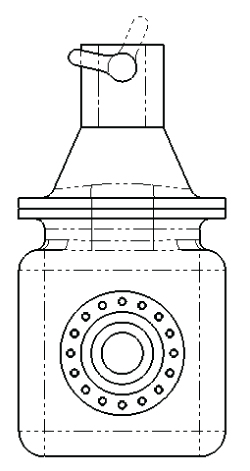
FIGURE 25.41 Creating an alternate position view
- Place an isometric view on the drawing. Change the Display Mode to make it a shaded view.
- Right-click inside the view, but away from the parts, and select Properties. The dialog box will appear, as shown in Figure 25.42. Make sure that the view is set to use the default configuration, and select the Show In Exploded State option.
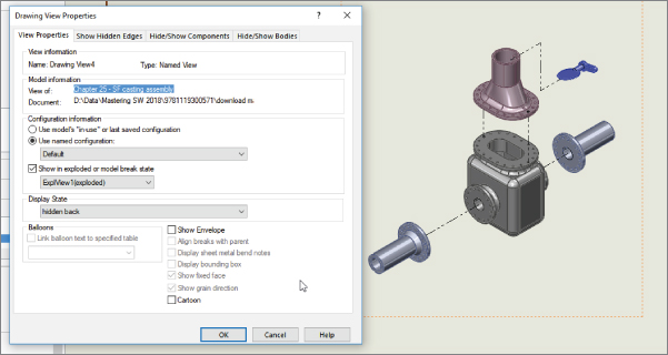
FIGURE 25.42 The Drawing View Properties dialog box
The Bottom Line
SolidWorks has the capacity to make many different types of views of parts. In addition to the tools for projecting views, custom views saved in the model document can be saved and used on the drawing. The associative nature of the drawing to the model helps ensure that drawing views, regardless of how unusual the section angle or view orientation, are displayed in the correct size, location, and geometry.
It's sometimes better to create some of the views that require sketches by pre-sketching. Utilize workflow enhancements when possible; for example, the automated workflow of the Broken-Out section works well, but forcing it to be a manual process makes it awkward to use.
- Master It Included with the downloads for Chapter 1, “Introducing SolidWorks,” you will find a folder full of document (part, assembly, and drawing) templates. Using Windows Explorer, sort the templates and copy the
*.drwdottemplates into the location specified at Tools ➢ Options ➢ System Options ➢ File Locations ➢ Document Templates. - Master It Use the Robot Arm assembly in the download data for this chapter to create a drawing that uses an alternate position view on the first page and drawing views of the individual parts on pages after the first one. Make sure to use a template with a special page 2 format.
- Master It Create a new drawing, and place two views on it using separate parts (using the Model View tool). Next, rotate one view 90 degrees and align it with the second view.