An advertising agency had a small, makeshift recording facility which was both cramped and poorly laid out. Expansion of agency business required moving up one floor in their large commercial building to provide the space needed. In the process the recording facilities were also to be enlarged and restructured. As is so often the case, those doing the actual recording work found themselves on the wrong end of the totem pole with their space shrinking daily as front office ideas grew during the planning stage. A space at one end of the floor between two concrete walls was eventually designated for studio use. The walls effectively blocked expansion north and south.
The primary use of this facility is in the production of radio advertising announcements. A secondary (but growing) activity is production of audiovisuals, principally slide sets and filmstrips. Two rooms were envisioned, one to be devoted principally to the recording and audiovisual functions, the other to be a combination control room for recording and a general work room in which mixing, editing, and dubbing would also be done. Several people, each working on a different project or at least different aspects of the same project, were bound to get in each other’s way from time to time but the “gigantic step forward for mankind” which the new facility offered over the old one made such conflicts seem trivial.
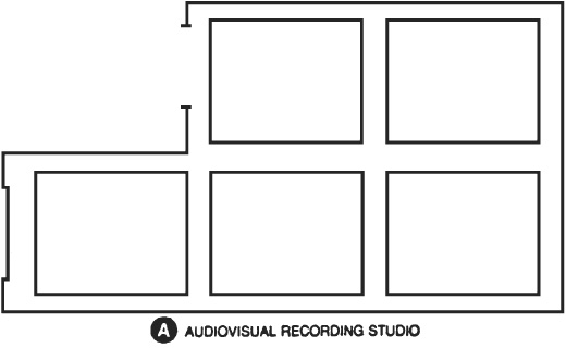
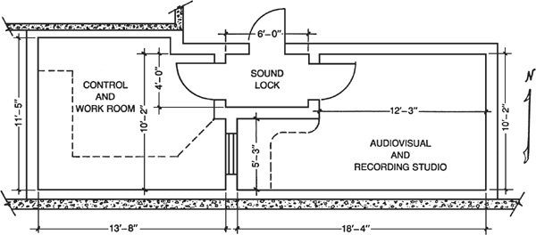
The floor plan emerging from the smoke and fire of space allocation, incorporating the best functional ideas of production personnel and the acoustical consultant, is shown in Fig. 11.1. It incorporates some basic problems, such as volumes below the 1500 cubic foot minimum (but not much below). Because sound lock space had to be taken from the studio, a cavity is created in the recording studio near the observation window. The temptation to sit in this cozy indentation at the built-in table near the window is great, especially for those nurtured on the radio tradition of the announce booth. The better position for the narrator during recording is back in the main part of the room and not in this indentation. The indentation would not have existed if sound lock space could have been allotted outside the studio area.
FIGURE 11.1 Floor plan of work room and recording studio wedged in between two existing concrete walls. Due to space limitation it was necessary to take the sound lock space from the studio.
The control work room has a built-in work surface along the south and west sides of the room. This bench carries a mixing console as well as numerous advanced audiophile-type magnetic recorders.
As discussed in Chapter 1, axial mode distribution is something of a problem even when we are free to specify the three dimensions of a room. In this case, two of the three dimensions of both rooms were fixed by circumstances and tight constraints were placed on the third. All that can be done in such circumstances is to study the distribution of fundamental resonance frequencies and harmonics of the space in an attempt to evaluate the threat of colorations on paper before construction is started.
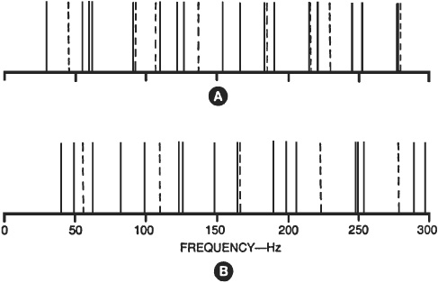
Figure 11.2A is a plot of modal frequencies for the audiovisual/recording studio. The solid lines are associated with the basic 18-foot 4-inch length, 10-foot 2-inch width, and 8-foot 11-inch ceiling height (the length of the lines of Fig. 11.2 holds no significance). The broken lines are associated with the 5-foot 8-inch alcove in the N-S mode and the 12-foot 3-inch step in the E-W mode.
FIGURE 11.2 Distribution of axial modal frequencies: (A) for the audiovisual recording studio and (B) for the control work room. The solid lines are associated with the basic dimensions of the rooms, the broken lines with secondary dimensions of alcove and step.
Some of these secondary dimensions within the room (broken lines) occur in rather large gaps between major resonances (solid lines), which is favorable, while others are almost coincident with major dimension modal frequencies, which can be unfavorable. The triple coincidence at about 277 Hz is probably no threat because few colorations are found to be problems above 200 Hz. The three or four double pileups or near pileups below 200 Hz may or may not be troublesome. These will require the application of a keen ear for evaluation.
The solid lines of Fig. 11.2B represent the modal resonance picture for the control work room major dimensions of a 13-foot 8-inch length, 11-foot 5-inch width and 8-foot 11-inch ceiling height. The broken lines are associated with the 10-foot 2-inch N-S secondary step in the room width. With the exception of one at 167 Hz, all the secondary resonances land nicely between the major dimension resonances. In our keen ear analysis of this room, particular attention should be given to the possibility of colorations due to the double coincidences near 125 Hz and 166 Hz.
It was immediately recognized that other diverse and noisy activities in the building could easily be carried to and radiated in the sound sensitive spaces by the concrete structure of the building. For example, elevator equipment mounted securely to the structure sends impulses into the reinforced concrete walls and pillars and these can be radiated into the studios by concrete surfaces acting as diaphragms. Isolating against such noises took on a high priority. Floating concrete floors were ruled out by budget limitations, but something could be done about walls and ceilings.
Walls paralleling existing concrete surfaces are set back, creating a 3-inch air space filled with glass fiber insulation. Metal studs 2½ inches thick form the framework and a double layer of  -inch gypsum board make up the mass of the wall surface facing the studio. Other walls, including the one in which the observation window is set, are constructed as double metal stud walls separated by 3 inches. The space is filled with glass fiber insulation. Double gypsum board on both faces yield an overall wall 10½ inches thick with a rating in the vicinity of STC-50. The ceiling is suspended from the structural ceiling with a vibration isolation hanger on each wire. A black iron angle frame holds the double -inch gypsum board ceiling. All gypsum board edges are staggered and all joints caulked with nonhardening acoustical sealant.
This plan provides a reasonable degree of isolation from building sounds on all surfaces but the floor. It was decided that if the floor did become a problem, a wooden floating floor could be added at a later time at minimum cost.
Such structure-borne sounds can be a serious problem. For example, I visited a fabulous new government broadcasting house in a certain foreign land. The architect had claimed 90 dB transmission loss as protection against nearby jet landing pattern noise by the studio-within-a-studio technique. Stepping into one of the beautifully treated and decorated studios, however, a distinct hammering noise from another part of the building was clearly heard to the embarrassment of the engineer-host.
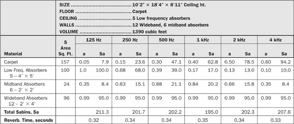
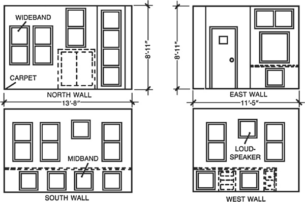
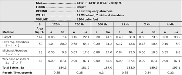
The acoustical treatment of the audiovisual recording studio involves four basic elements: the carpet, wideband wall units (2 feet × 4 feet), midband wall units (2 feet × 2 feet), and the low frequency ceiling units (4 feet × 5 feet). The absorption of the gypsum board walls and ceiling has been neglected in the discussion to follow, but will be treated later in the chapter.
Figure 11.3 shows the placement of the wall units, Fig. 11.4A the placement of the ceiling units and Table 11.1 tabulates the computations for this room. Entering into Sabine’s formula the room volume of 1390 cubic feet and the reverberation time goal of 0.3 second gives a required absorption of 227 sabins. The problem now becomes one of juggling the areas of the four types of absorbers to give close to 0.3 second reverberation time across the band.
FIGURE 11.3 Wall elevations of audiovisual recording studio showing placement of wideband and midband absorbers.

FIGURE 11.4 Projected ceiling plans showing placement of the 4-foot × 5-foot low frequency units on the ceiling: (A) audiovisual recording studio and (B) control work room.
TABLE 11.1 Audiovisual Recording Studio Calculations
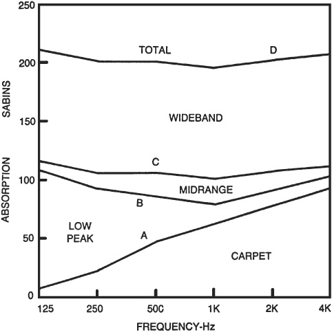
To obtain a uniform reverberation time throughout the audible spectrum requires a constant number of absorption units (sabins) with frequency. In Table 11.1 the total sabins at each frequency is fairly close to the calculated 227 required, varying from 195 to 211.3. To see more clearly how absorption of each type of material varies with frequency, the data of Table 11.1 is graphically presented in Fig. 11.5. The greatly unbalanced carpet absorption (Fig. 11.5A) is quite well compensated by the equally, but opposite, absorption of the low frequency ceiling units. However, there is a sag at midrange frequencies of the low frequency plus carpet curve (Fig. 11.5B) and the midrange units, tuned to the 500 Hz-1 kHz region, are designed to straighten out the carpet + LF + midrange curve (Fig. 11.5C). Once this is done, enough wideband absorber is introduced to raise the total to approximately the 227 sabin level (Fig. 11.5D). This gives close to 0.3 second reverberation time across the audible range shown in Fig. 11.6.
FIGURE 11.5 Distribution of room absorption between the four principal types of absorbers used in treating the audiovisual recording studio.
FIGURE 11.6 Reverberation time of the two rooms as a function of frequency.
The low frequency units are most properly placed opposite the carpet for which they compensate, in the usual contracarpet position. The area required for these LF units means that 100 square feet, or 64 percent of the total ceiling area be covered with these 4 foot × 5 foot boxes, but leaving enough space for illumination fixtures. The facings of the low frequency units are quite reflective at the higher frequencies, but vertical flutter echoes are controlled by the carpet absorption.
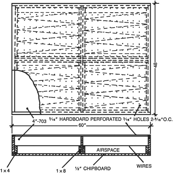
The construction of the ceiling low frequency units is detailed in Fig. 11.7. The frame and center divider are made of 1 × 8 lumber strengthened by a backing of ½-inch chipboard on plywood. A facing of 3/16-inch tempered hardboard perforated with 3/16-inch holes spaced 29/16 inches on centers covers the entire frame. In intimate contact with the perforated cover inside the box is a 4-inch thick layer of Owens-Corning Type 703 Fiberglas of 3 pounds per cubic foot density.
FIGURE 11.7 Constructional details of the Helmholtz low-frequency absorbers to be mounted on the ceiling.
If the glass fiber material is loosely fitted, something is needed to hold it against the perforated facing. The 1 × 4 spacers with fine wire tacked to the edges in a zigzag form will do this in a very positive way, but if gravity and friction can be depended upon to hold the glass fiber snugly against the back of the perforated cover, so much the easier and cheaper. The air space plays an active part in the performance of this absorber. The boxes can be mounted to the ceiling in any convenient way. Painting these units and the exposed parts of the ceiling flat black will render them visually unobtrusive, especially if the illumination fixtures direct the light downward. Track lights are ideal for this.
Hand drilling almost 500 holes in each of the nine ceiling box covers can be a staggering job. The obvious way to minimize this is to stack all covers, drilling all with one set of holes. Each cover can be split at the center divider if desired so that 18 pieces of 30 inch × 48 inch hardboard could be stacked for drilling.
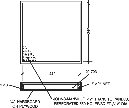
The midband units have a relatively minor, but important, role to play in the overall treatment of the audiovisual recording studio as illustrated in Fig. 11.5. They are mounted on the wall under the window table and along the lower edge of the south wall in Fig. 11.3. Their simple construction is detailed in Fig. 11.8.
FIGURE 11.8 Constructional details of the midband absorbers having peak absorption in the 500 Hz-1 kHz region.
The covers are Johns-Manville Transite panels which come perforated with 550 3/16-inch holes per square foot. These are autoclaved asbestos cement boards 3/16-inch thick and their 24 inch × 24 inch size determines the size of the supporting frame. This frame is made of 1 × 3 lumber with 1 × 2 spacers inside. The 2-inch dimension should be met to accommodate the 2-inch thickness of the Owens-Corning Type 703 Fiberglas.
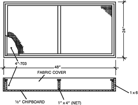
Acoustically speaking, the 2 foot × 4 foot wideband units are nothing more or less than 4 inches of 703 Fiberglas of 3 pounds per cubic foot density. The rest is mechanical mounting and cosmetic cover. Figure 11.9 shows how the 1 × 6 frame, 1 × 4 divider and spacers, and the ½-inch chipboard backboard fit together.
FIGURE 11.9 Construction details of the 2-foot × 4-foot wideband modules. These are basically 4 inches of 703 glass fiber with mechanical protection and cosmetic cover.
The manufacturer of the glass fiber stops short of attributing 100 percent absorption to 4 inches of 703, listing 0.99 as the coefficient from 125 Hz to 4 kHz.
Below 125 Hz the absorption does fall off, of course, but in this low frequency region the diaphragmatic absorption of the five gypsum board surfaces tends to compensate. The double -inch gypsum board surfaces resonate well below 125 Hz. Calculations indicate that the walls paralleling the existing concrete walls on the north and south sides with 5-inch air space have an absorption peak at about 32 Hz. The other walls with their 8-inch air space peak near 26 Hz. These cavities are filled with insulation which increases the breadth of the absorption region markedly, but the resonance frequency little. No values of measured absorption coefficients are available for double -inch gypsum board walls with these cavity depths. However, by taking the values available for ½-inch gypsum board on 2 × 4s 16 inches on centers and shifting them to take into account the different resonance frequencies involved, an absorption coefficient of 0.05 to 0.08 is estimated for 125 Hz.
With a gypsum board area of about 580 square feet involved in the audiovisual recording studio, something like 30 to 40 additional sabins may be at work at 125 Hz because of wall absorption. This would reduce the reverberation time at 125 Hz to something like 0.23 second and be less effective than this at 250 Hz and above. This possible 23 percent reduction of reverberation time at 125 Hz requires measurements to tie it down specifically, but this discussion points out that such wallboard absorption might reduce the required area of ceiling low frequency absorbers.
The control work room is treated with the same four elements as the audiovisual recording studio: carpet, wideband and midband wall units, and ceiling mounted low frequency absorbers. Figure 11.10 shows the suggested placement of each unit on the walls and Fig. 11.4B the placement of the four low frequency units on the ceiling. Table 11.2 lists vital statistics of this room as well as the absorption units (sabins) expected of each of the four elements at each of the six frequencies.
FIGURE 11.10 Wall elevations of control work room showing placement of wideband and midband absorbing units.
TABLE 11.2 Control Work Room Calculations
There is little need to plot the contribution of each of the four elements. Although the values differ somewhat, the general apportionment principle revealed in Fig. 11.5 for the audiovisual recording studio applies to this room as well. The calculated reverberation times of Table 11.2 are plotted in Fig. 6.6 for ready comparison with those for the other room.