
The LaunchPad computer has the ability to sense when things change in its environment. Simple changes, such as someone pressing on the onboard switch, have already been discussed to some extent. But the LaunchPad can also sense voltages on several of its pins, and it can use its timers to detect the width of HIGH or LOW pulses on an input pin. Using these capabilities, you can detect changes in light levels, temperature, distance to objects, pressure, sound, and many other things going on in the nearby environment.
Measuring temperature requires nothing but the LaunchPad itself. It has an internal temperature sensor. At the factory, technicians calibrated this sensor by recording its output at two different temperatures: 30 degrees Celsius and 85 degrees Celsius. They then wrote these two values into the memory on the chip. When the sensor is read, you can use the known values at those two temperatures to convert the reading into degrees.
The code is too long to show as a single image, but you can reference this link to see it: http://artists.sci-toys.com/temperature.txt.
The LaunchPad has an internal analog-to-digital converter. It can convert a voltage into a number the computer can use. The analog-to-digital converter—ADC for short—needs to compare the voltage to a known reference value. You can choose to use the voltage that runs the chip, but that might not be well regulated (you can run the chip from a battery, whose voltage drops as it weakens). But the LaunchPad chip also contains a 1.5-volt reference voltage that is quite stable and accurate. So you will use that. The setup and loop functions look like this:
In setup(), you use the function analogReference() to tell the chip to use the internal 1.5-volt reference. Then you use analogRead( TEMPSENSOR ) to read the temperature. You throw away the first reading, since it is generally unreliable.
In the loop() function, shown on the next page, you use your own function temperature() to read the temperature sensor many times and average the results, and then convert the average temperature into degrees, using the factory calibration values.
For those who would rather see the temperature in Celsius, I left that line in as a comment.
In this program I use the Serial class to send text back to the computer that is used to program the LaunchPad. In order for this to work, you need to change the jumpers (labeled J3) on the LaunchPad board from their default “software UART” positions to the “hardware UART” positions. This is quite easy, as there is a picture printed on the board to remind you which way to set the jumpers. Pull out the two leftmost jumpers, turn them 90 degrees, and put them back, as shown in the photo below.
A UART is the universal asynchronous receiver/transmitter. That is geek speak for serial port—a way for computers to talk to one another.
Once you have set the jumpers and downloaded the program to the LaunchPad, you can bring up the serial monitor window (using the Tools menu, Serial Monitor menu item, or just holding down the Control and Shift keys while you type M for “Monitor”). That window will show the text the LaunchPad is printing.
However, in a sculpture, you might use a servomotor to move an arm to indicate the temperature outside (“The temperature is this high …”). Or you might have the computer play a different tune depending on the temperature. Or maybe say something about the weather. Or just indicate the temperature using lights or an LCD display.
Light-emitting diodes work both ways—they emit light when you put power into the leads or they can generate power out of the leads when you put light into the lens. They are a type of solar cell, like what you might find in a calculator or on someone’s roof.
The amount of power is tiny, since the little chip in the LED can’t collect very much light energy, due to its small surface area. But the LaunchPad can detect and measure the power, using the analogRead() function.
You can attach an LED to one of the analog input pins, but you already have two LEDs mounted on the board—the red LED at P1.0, and the green LED at P1.6—so you will use those for this demonstration (http://artists.sci-toys.com /two_led_light_sensor_with_graph.txt):
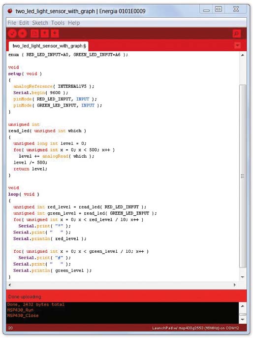
In the setup() function, you set the internal voltage reference to 1.5 volts. This is what you will compare the voltage from the LED to. A red LED might produce 1.5 volts from a very bright light, and so the number you get back from the analogRead() function would be 1,023, the highest value it can give. If you want to measure brighter light, you can set the internal voltage reference to 2.56 volts (using INTERNAL2V5) or use DEFAULT to let analogRead() compare to the 3.3-volt power supply.
Set the red and green LED pins to be inputs instead of outputs.
In the loop() function, read each of the LEDs and plot the reading on a poor man’s graph, using asterisks for the red LED and number signs for the green LED.
The read_led() function reads the value of the LED 500 times, and averages. This gets rid of random variations in the readings, what engineers refer to as noise.
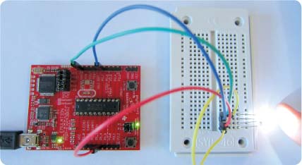
If you shine a light onto the LEDs, you can watch the graph change. As you move the light to shine more on one LED than the other, you can see one graph bar or the other (the asterisks or the number signs) get longer or shorter than the other.
With the ability to detect changes in light, your sculpture, robot, or other device can turn lights on when it gets dark, react to someone blocking a light, or react when a light is directed onto it. With two LEDs facing 90 degrees apart, you could have a flower that follows the sun or a robot that searches for a light to charge its batteries using solar panels. Some people build robots that follow a dark line on the ground, going around complicated courses by keeping the dark line always under the front-mounted sensors.
Using analogRead() to read the voltage produced by the LED is reasonably fast, but the LED is not very sensitive to low light levels when used in that fashion. There is another way to configure the LED as a light sensor, and it uses some tricks you learned very early in this book, when capacitors and their use as timers were discussed (page 33).
An LED is a block of semiconductor with two leads. Those two leads act as the plates of a capacitor. When you put a voltage on the LED in the wrong direction, so that it does not light up, the material between the two metal leads is not a conductor—it is an insulator. Two plates separated by an insulator is all a capacitor is, and the “reverse biased” LED is just that—a capacitor.
What makes the LED a particularly interesting capacitor is that it is light sensitive. When light strikes the semiconductor material between the two metal leads, it causes electrons to leave their atoms and become available to conduct electricity. So the LED material becomes slightly conductive when light hits it. When the capacitor is charged, one lead has a surplus of electrons, and the other has a deficit. If the material between them is not a good insulator, the electrons can move from the lead that has too many to the lead that is missing some. The charge stored in the capacitor seems to leak.
You can use this information to make a sensitive light detector. First, charge up the LED by putting a voltage across it in the “wrong” direction, the one that does not cause it to glow. You do this by connecting the LED (backward) to a pin and setting that pin high. Then make that pin become an input. As an input, the pin sees the charge you put on the capacitor, and you read it as high. But if there is light hitting the LED, eventually the charge leaks away, and the voltage you are seeing on the input pin drops to low.
By timing how long this takes, you get a reading on how bright the light was (on average) that was hitting the LED (http://artists.sci-toys.com/sensitive _proximity_detector.txt):

This trick gives you a very sensitive light detector (the LED I tested gave me readings of about 20 counts when in bright light to more than 2 million when I cupped my hand over the LED). That is equal to 16 bits of resolution, compared with the 10 bits available to analogRead().
The drawback is that it takes more time to get a reading in low light than the analogRead() function did. But since analogRead() gave you no ability to read such low levels, and no ability to read very bright light levels, this more sensitive detector has a place in your tool kit.
As a proximity detector (when combined with another LED to light up whatever is in front of it), the sensor was reliably detecting my hand from over a foot away when the room was dark. Using infrared or color filters might give good results even in a bright setting.

The circuit above shows the LaunchPad connected to an external white LED and an external red LED.
The white LED is connected to port 1 pin 7 and ground. The red LED is connected to port 1 pin 4 and ground.
The program at http://artists.sci-toys.com/simple_proximity_switch.txt keeps the white LED on and uses the red LED as a light detector. When you put something in front of the white LED, the red LED detects the reflected light, and that is read as a value returned from analogRead( A4 ).
The value is usually about 600 when nothing is reflecting the light back. When the light is detected, the value drops, reaching 0 if a white card is within about a quarter of an inch.
The program collects 100 readings in setup() to establish a baseline value for the condition when nothing is detected in front of the LEDs. It saves the largest value seen.
In the loop() function, you again read a value and convert it to a percentage of the maximum by first multiplying by 100 and then dividing by the saved maximum value.
If the percentage is less than 50 percent, you have detected something in front of the LEDs, and you turn on the onboard green LED to indicate that.
You selected the 50 percent value because there is a lot of variation in the readings, even when it looks like nothing has changed. Engineers call this kind of variation “noise in the signal,” and there are ways of dealing with it, to reduce its effects.
A second program, at http://artists.sci-toys.com/smoothed_proximity_switch .txt, smooths out the variations and allows you to use a 90 percent level as the criterion. You first collect 64 values and sort them, so the low values are at the top of the list and the high values are at the bottom. Then throw away the highest eight values and the lowest eight values, and average the values in between. The result is a much more consistent reading, with less variation caused by random effects. The variation you see correlates much better with actual changes in the distance between the LEDs and any object in front of them.

The photo on the previous page shows a sonar sensor called the HC-SR04 plugged into a solderless breadboard.
The sonar sensor sends out a pulse of ultrasound, well above the hearing range of people and animals. When it hears the echo, it brings one of its pins from ground to +5 volts, for a period that corresponds to how long it took the echo to come back.
Since the HC-SR04 is designed to run at 5 volts, you can’t simply power it from the LaunchPad’s 3.3-volt power supply. You have to find 5 volts somewhere.
You could simply use a second power supply and connect the grounds together so the computer and the HC-SR04 both agree on what the 0-volt level is. But it just so happens that the LaunchPad gets 5 volts from the USB port of the computer it is attached to, and there is a hole in the circuit board you can solder a wire to that is connected to that 5 volts.

The hole in the circuit board is labeled TP1, which stands for test point 1. It is easy to insert a wire into the hole and solder it in place on the backside of the board, because there is almost nothing you can damage or mess up on that side. Even a novice at soldering can safely solder a wire there.
In the photo above you can see the two holes next to the USB connector at the bottom right. The upper of the two holes is TP1.
The HC-SR04 puts out 5-volt signals, which the LaunchPad can’t read. You need to drop the voltage down to between 1 and 3.3 volts. The simplest way to do this is to limit the current with a 1,000-ohm resistor. Because there is less current, the voltage will drop to something the LaunchPad can handle.
The HC-SR04 has four pins. Connect +5 volts to the pin labeled Vcc. Connect the pin labeled Gnd to ground. The Echo pin is the output that needs to have the 1,000-ohm resistor. The other side of that resistor goes to an input pin. In the example program, that will be port 2 pin 1.
The remaining pin is the Trig pin. Setting that pin high tells the device to send out a pulse of ultrasound. The LaunchPad can raise this pin to 3.3 volts, which is short of the 5 volts that the HC-SR04 expects but high enough to be accepted as a HIGH signal.
In the example program at http://artists .sci-toys.com/sonar.txt, the setup() function starts the serial port after a five-second delay to allow you to bring up the serial monitor window. It then prints a startup message and sets up the port pins.

In the loop() function, you get the average distance the sonar sensor sees in front of it, and print that out. Then you send out a beep to a speaker connected to port 2 pin 3. The frequency of the tone corresponds to the distance between the sensor and what it is sensing.
The program has its own beep() function, because the tone() function supplied in the standard library uses a timer that is also used by pulseIn(), and it will need to use the pulseIn() function to read the sonar sensor.
The get_distance() function is what does the sonar sensor reading. It sends out a five-microsecond pulse to the sensor’s Trig pin to tell the sensor to send out a sonar pulse. Then you time the resulting signal from the Echo pin using pulseIn(), which returns the length of the pulse in microseconds. Convert that time to centimeters by dividing by twice the speed of sound in microseconds per centimeter (which works out to be 58.77).
As you did with the LED proximity sensor, you filter the results by sorting samples and averaging those near the median.
As you move your hand toward the sensor, the pitch of the beeps rises. As you move away, the pitch falls.
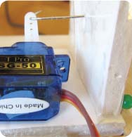
Inexpensive piezoelectric elements are usually used to make sound. But in this project you will use one to generate a voltage when it is tapped lightly with a finger.

Connect the piezoelectric element to port 1 pin 4 and ground, as shown in the above photo. Now you can simply loop, sampling port 1 pin 4 with digitalRead() or analogRead(), but that approach has two problems. First, by doing things that way, you might miss an event that has a very short duration, especially if you are doing anything else in the loop. Second, and related to the first, it means that you can’t do much else in the loop for fear of missing a short event like a finger tap on the sensor.
However, the LaunchPad has a feature you haven’t yet used that makes those problems go away. You can tell the LaunchPad that if port 1 pin 4 goes from low to high, you want the processor to interrupt whatever you are doing and call one of your functions.
The function you want to have execute when the pin goes high is called felt_tap(). All it does is change a variable from false to true. You generally want to keep interrupt routines very short so they execute quickly and don’t interrupt other processes much. It is somewhat like getting a phone call while you are driving—if your attention is drawn away from the road for too long, bad things can happen.
The variable you are changing must be declared volatile so the compiler knows that it can change out from under you at any moment. Otherwise the compiler might notice that it does not seem to ever change and might optimize the code to eliminate any uses of it.
In setup(), you tell the LaunchPad that felt_tap() is supposed to be called on during rising transitions of the pin by using this line:

Just for fun, you also want to use the piezo element for its more common purpose: to make noise. To do that, you need to convert the pin from an input to an output. But you also want to tell the LaunchPad not to interrupt while you are using the pin as an output, because otherwise the moment you make the pin an input again, you would get an interrupt and mistake it for a finger tap.
So the beep() function detaches the interrupt routine from the pin using the line

Then beep() sets the pin to be an output, toggles it at the right frequency for the right amount of time so you hear a beep, and then sets it back to being an input and attaches the interrupt function again before it returns.
In the loop() function, you want to ignore any bouncing you get when the sensor is tapped. When you touch the sensor, it might give you many interrupts in a row as the sensor creates several spikes of voltage due to continued flexing of the piezoelectric ceramic. So you use the function millis() to ask how many milliseconds have elapsed since the LaunchPad was turned on. Then you ignore any incoming events for the next 100 milliseconds. That gives the sensor time to settle down.
Turn on the green onboard LED when it first detects a tap. The next tap turns it off. If you are turning the green light on, you also call beep(), to give extra feedback to the user. You get an input device and an output device in the same little package (http://artists.sci-toys.com/tap_sensor.txt).
When building an electronic sculpture, you are usually interested in giving it behavior. You don’t simply want to have it flash lights and move motors, you want it to interact with its environment as if it were alive. This kind of behavior is called agency.
Cecil is a sock puppet made to look like a sea serpent. The photo on the next page shows him without his sock puppet skin, so you can see his inner workings. His eyes are the two ultrasonic transducers that view the area immediately in front of him and notice changes in the distance between the robot and people passing by.
When at rest, Cecil stands up straight. If he notices that something is within about a meter in front of him, he leans forward, as if curious. This is accompanied by the sound of the gears in his servomotor, which attracts the attention of a person passing by. If that person comes within about a foot of Cecil, he starts backing away, as if apprehensive about someone invading his personal space.
This simple behavior is enough to delight anyone coming in contact with him for the first time. He seems to have agency, giving a sense that he has a mind and that he has feelings such as curiosity and shyness.
Hidden in Cecil’s wooden box base is a LaunchPad and a solderless breadboard. The breadboard is not really even needed, as it is only used to hold a single resistor that could easily have been soldered to the wire leading to the sonar sensor. As you saw in the first sonar sensor program (page 134), that resistor allows the 5-volt sonar sensor to communicate with the 3.3-volt LaunchPad.

The other piece to Cecil is his servomotor. No other electronic parts are needed.
A simple trick of geometry is used to keep Cecil’s head level as he leans forward and back. You form a parallelogram of wood slats, or in this case foam-core board, which makes prototyping fast and easy. The hinges are simply clear packing tape. As you push on a parallelogram, it can become a rectangle when the sides are upright, or it can slant forward or back, but at all times the top side is level with the bottom side. This keeps Cecil’s sonar sensor always looking forward, never upward or downward.
The servo is connected to the back slat by a stiff steel wire, as seen in the photo to the left. As the servo turns, it either pushes or pulls on the back slat, by means of the stiff wire.
See the sections on servomotors (pages 54 and 104) and the sonar sensor (page 134) for details on how to connect and use these parts. They are simple, and your little robot goes together quickly.
The code for detecting distance using the sonar sensor is taken from that project and is explained there. The rest of the code should be simple to follow; see http://artists.sci-toys.com/cecil.txt. The loop() function gets the distance, and if nothing is detected, it directs Cecil to straighten up. If something is within about 3 feet or so, the code calls lean_in(). If the distance is a foot or less, the code calls back_up().
The lean_in() function decrements the angle of the servo a little bit each time it is called, until it reaches a limit (MIN_ANGLE). The back_up() function does the same thing in reverse. The straighten_up() function changes the angle by one degreee in the direction of 90 degrees each time it is called.
In setup(), you use P2.0 for the servomotor output, P2.1 for the sonar sensor input, and P2.2 for the sonar trigger. Wait six seconds before printing anything to give you time to open the serial monitor window.

There is nothing new to learn in this project. It is just a collection of things you have already done. You built a motor controller using the SN754410 H-bridge chip (page 102). You controlled servomotors (page 104). You detected distance using sonar (page 134).
All of those projects come together in Rover, a little robot that scans his surroundings and rolls along while avoiding obstacles. This project is based on some very clever designs by Alexander Reben, to which I have added extra goodies (like the sonar scanner) and all the software, which you’ll find at http://artists.sci-toys.com/rover.txt.
The photo above shows Rover as seen from above. You can see the HC-SR04 sonar sensor is glued to the arm of a small servomotor. The servo can thus rotate the sonar sensor to get an idea of the distances in front of the robot, allowing him to know where obstacles are in front and to the side and where the wide-open spaces are.
From behind you can see that there are two yellow DC gear motors with wheels, attached to a cardboard box with cable ties. A third cable tie is seen in the back, acting as a rear ski for low-friction support. Each of the two motors can move in forward or reverse, allowing the robot to spin left or right in place, or move forward and back.
Opening up the lid shows Rover’s insides, a crazy rat’s nest of wires but simple to understand when you look at each function separately.

The black box under the LaunchPad holds 4 AA cells, used for power when the robot is not connected to the USB port. That provides 4.5 volts, which is enough to power the sonar sensor and the DC motors. The black ground lead from the batteries is stuck in an empty hole in the solderless breadboard when the robot is not powered up. To turn the robot on, that lead is placed in a hole connected to one of the four ground pins on the SN754410 H-bridge chip. That saves having to buy a switch.
Both sides of the H-bridge chip are used, since Rover has two motors.
The wheel on the right is connected to the H-bridge so that the LaunchPad’s P1.2 and P1.4 control whether the wheel is off, moves forward, or moves back. The left wheel is controlled by the LaunchPad’s P1.6 and P1.7.
The sonar sensor is connected to P2.2 for the trigger and P2.1 for the echo. The echo has a 1,000-ohm resistor between the sensor and the LaunchPad. The sensor is powered from the battery, since it needs 4.5 to 5 volts.
The servomotor is controlled by P2.0. It gets its power from the battery.
A tiny speaker is attached between P2.3 and ground so that the robot can beep.
A clever trick Alexander Reben used is to take the box the LaunchPad came in and carefully turn it inside out so the outside is white. This is used for the body of the robot. (In the photos for this secton, I actually used a different but similar box I had lying around.)
Some ideas for improvements:
Mount the batteries on top of the robot and give them a female USB connector. Then the “tail” of the robot would plug into the batteries to act as the power switch. Inside the robot, the 5-volt power could come from a wire soldered to the LaunchPad’s TP1 test point near the USB connector.
Use the LED proximity switch (page 132, mounted so it looks down in front of the robot) so the robot can tell if it is about to fall off the table.
Write more code to control the robot’s behavior. You can use the proximity switch to let it follow a black line on a white surface, for example, by putting two detector LEDs on either side of the white LED. Now the robot can follow a complicated course that you draw on paper with a black felt pen.
Replace the motors and servo with quiet stepper motors so the robot can sneak up on people.


