6
The Laws of Spinal Mechanics
Spinal Mechanics: Fact or Fiction?
A medical doctor by the name of Robert Lovett was the first person (I believe) to confirm coupled spinal motions, other than the standard primary motion of flexion and extension (Lovett 1903). He believed that side bending and rotation of the spine are parts of one compound movement and cannot be dissociated: he found that a flexible rod bent in one plane could not bend in another plane without twisting. In all his experiments Lovett proved that if the spine was in a position of lordosis, it rotated in the opposite direction to that of the side bending motion; moreover, if the spine was in a position of kyphosis, it rotated in the same direction as that of the side bending motion.
He considered that only three spinal movements were possible within the vertebral column: (1) flexion; (2) extension; and (3) side bending with rotation. He also concluded that side bending, or lateral flexion, must accompany spinal rotation (i.e. the motions are coupled).
Lovett proposed that coupled motion occurs in a second plane of motion within a joint system, and is part and parcel of the primary motion. Two or more motions are considered “coupled” when it is not possible to produce one motion without inducing the second one; spinal coupling occurs because of the morphological shape of the facet joint surfaces and the connecting ligaments and spinal curvatures.
In the early 1900s the osteopath Harrison M. Fryette contributed some pioneering work on the mechanics of spinal motion. He spent many years of his life researching this topic and eventually presented a paper in 1918 on the principles of spinal motion, which was sent to the American Osteopathic Association (Fryette 1918).
Initially, Fryette’s paper was poorly received and he did not gain acceptance. Many years passed before he eventually received formal recognition for his ideas. In the late 1940s Fryette was invited to the UK by Edward Hall to do a presentation on his work. Fryette spoke about what he called “The Total Osteopathic Lesion,” and he had such a profound effect on Hall that his biomechanical view of spinal motion was relabeled to “Fryette’s Laws of Spinal Mechanics,” which up until then had been referred to only as principles. (Hall wrote the first article on that subject in the 1956 yearbook of The Osteopathic Institute of Applied Technique.)
A quote from Fryette:
“No intelligent scientific spinal technic can be developed that is not based on an accurate understanding of the physiological movements of the spine.”
Regarding the motion of the spine, Stoddard (1962) states the following in his manual on osteopathic technique:
“Rotation of the spine is always accompanied by some degree of lateral flexion. Likewise, lateral flexion of the spine is accompanied by some degree of vertebral rotation.”
How All This Came About
Fryette utilized and established correlations with a lot of the earlier work conducted by Lovett in 1903. The research methodology consisted of cadaveric study and in vivo research via the application of gummed paper stickers. These bits of sticky paper were attached to the spinous processes of the vertebrae of a small number of individuals; the results were then obtained by observing the relative spinal motion of these gummed paper stickers.
It is hard to appreciate how much the research into spinal mechanics has progressed over the last 50–100 years, from the simple observatory techniques of Fryette employing sticky paper to the use of advanced technology such as computer simulation, computerized tomography (CT scan), magnetic resonance imaging (MRI scan), and cineradiology (viewing an organ in motion with a special movie camera). We can even detect motion of the spine and pelvis by implanting gallium balls and Steinman pins.
If we were able to jump ahead into the future by, say, 100 years, it would be very interesting to see what actually changes in terms of research and technology. It goes without saying, especially as time passes, that the more we are able to visualize and research living spinal motion, the more complex and unpredictable the precise combination of individual spinal joint motion becomes for each particular area and segment of the vertebral column.
I have read numerous articles and many books by various authors over the last few years while researching the subject of spinal motion, before eventually deciding to write this particular book on the pelvis and SIJ. Those practitioners in question, who I consider to be experts in their field of manual therapy, all seem to have a slightly different opinion on spinal mechanics/motion, which I think is fine, as everyone is entitled to have an opinion. Some of the information that I have read, however, actually comes across as rather conflicting, because there currently does not appear to be any standardization in this field of study. Rather than having what we call definitive “laws of spinal motion” or “principles of spinal motion,” there are substantial individual and regional variations, and, as yet, no true accurate model for predicting the behavior of the vertebral column as regards specific motion.
Koushik physio (2011) says in his website blog:
“The work of Fryette must be applauded for its longevity and insight, and celebrated as part of our osteopathic heritage and history, but the “laws” can no longer be viewed as such, nor do they serve as a viable explanation of physiological motion behavior. With all this uncertainty why do some of us still persist in promoting a model for physiological motion based on work conducted over 100 years ago?”
In one way I totally agree with what this author says. Yes, I am basically of the same mind that perhaps the work of Fryette might be outdated; however, another part of me totally disagrees with what is being said. Why, I hear you ask? Because I spend a lot of my time traveling the world, as well as the UK, teaching a variety of physical therapy courses; when these courses relate in particular to the motion of the spine, it amazes me that the majority of therapists who I come into contact with have not been taught anything about the specific motion of the vertebral column and the biomechanics of the pelvic girdle/SIJ during their own studies … and this truly disappoints me. This is true even in the case of qualified and experienced osteopaths, chiropractors, and physiotherapists.
These days, if I am honest, I have no idea of the current criteria for what is actually covered in terms of spinal motion in specific degree courses run in the UK. One thing I know for sure, however, is that there cannot be much time spent learning about this fascinating area during these undergraduate and even postgraduate courses, as otherwise my own physical therapy courses would not be as busy as they are.
I therefore now have a dilemma: I must at least teach a concept of spinal motion to my students, so the question is, do I teach a concept from Fryette that has been around for over 100 years and is considered by some to be outdated—even though some experts say Fryette’s views should not be used any more? Or do I teach what is believed to be the most recent findings, as contradictory as they might be?
The answer is that I of course teach Fryette’s Law, as my own personal approach to this is the following. I teach my students one way, one method, and as I have already said, I use the concept of Fryette’s way of thinking about the way the spine moves. At least then, I honestly believe, after completing my course the students (including the more experienced therapists) will actually be able to get to grips with, and hopefully have a far better understanding of, the concept of Fryette’s laws and the underpinning principles and concepts of spinal mechanics.
Ultimately I am more than happy that those therapists who have chosen to attend my courses will have a good initial grounding in applying the laws of Fryette, hopefully with specific relevance and application to their own private patients and athletes presenting with back or pelvic pain. Naturally, over time, things progress, especially in relation to current research methodology and technology. Therapists can themselves gradually evolve their techniques in practice as they become more experienced and knowledgeable, so they should be able to adapt very well to those ongoing changes.
Gracovetsky’s “Spinal Engine Theory”
Serge Gracovetsky (1988) elaborated on a particular idea of spinal motion, which he discussed in his book The Spinal Engine. He considered the spine to be the “primary engine” in the role of locomotion and proposed that the legs were not responsible for gait, but were merely “instruments of expression” and extensions of the spinal engine. He argued that the spine was not a rigid lever during the gait cycle and that its ability to produce axial compression and torsion was a fundamental driving force during locomotion.
In his discussions Gracovetsky says that during heel-strike, kinetic energy is not displaced into the earth as in the pedestrian model, but efficiently transmitted up through the myofascial system, causing the spine to resonate in the gravitational field. He did not view the spine as a compressive loading system, whereby the intervertebral discs act as shock absorbers; he regarded the outer annulus disc fibers and their accompanying facet joints as dynamic antigravity torsional springs that store and unload tensional forces to lift and propel the body in space. He also considered that the natural process of interlocking of the facet joints and intervertebral discs transmitted virtually all of the available counter-rotational pelvic torque that is needed to aid the inner and outer core muscles for locomotion.
A quote from Gracovetsky:
“The spine is an engine driving the pelvis. Human anatomy is a consequence of function. The knee cannot be tested in isolation, as it is part of the overall function and purpose of the musculoskeletal system. The leg transfers the heel-strike energy to the spine. It is a mechanical filter. The knee is a critical part of that filter and improper energy transfer will affect spinal motion. Functional assessment of the spine ought to be part of the assessment of knee surgery.”
Let’s think back to the earlier concept of Lovett: it is this lumbar lateral flexion/rotation coupling that serves as the Gracovetsky spinal engine “drivetrain.” For example, left lateral lumbar flexion will drive right rotation of the lumbar spine, and subsequently the SIJ and pelvis.
What I would like to do now is return to the discussion of Chapter 4 and in particular of the gait cycle, and look at this concept in a slightly different way. Some authors have considered that the biceps femoris muscle of the hamstring group, along with its connection to the posterior (deep) longitudinal sling (Figure 6.1), effectively starts the spinal engine. The biceps femoris has been likened to the pull cord of the spinal engine in view of its action of inducing a “force closure” mechanism in the SIJ. This closure of the SIJ will naturally lead to a subsequent transmission of force up into the osteo-articular-ligamentous tissues of the lumbosacral spine; this force will eventually continue into the muscles of the lumbar erector spinae.

Figure 6.1. Posterior (deep) longitudinal sling.
EMG studies have demonstrated that the biceps femoris muscle is particularly active at the end of the swing phase of gait, through the early loading of the stance phase. During the transition from swing to stance, the heel contact phase of the gait cycle effectively closes the kinetic chain, and the biceps femoris can now perform its work in a manner that is commonly called a closed kinetic chain. Within the closed chain, the biceps femoris acts on its more proximal attachment within the chain, namely the pelvis. The biceps femoris attaches directly to the ischial tuberosity and also to the sacrotuberous ligament, sacrum, iliac crests, and up through the multifidi and lumbar erector spinae (see figure 6.1).
At heel contact the ipsilateral (same side) hip and contralateral (opposite side) shoulder are in a position of flexion, which effectively preloads the posterior oblique sling (Figure 6.2(a)), specifically the ipsilateral Gmax and contralateral latissimus dorsi. This allows extra-spinal propulsion in a “sling-like” manner, with the superficial lamina of the thoracolumbar fascia serving as an intermediary between these kinetically linked muscles as shown by a person running by figure 6.2(b).
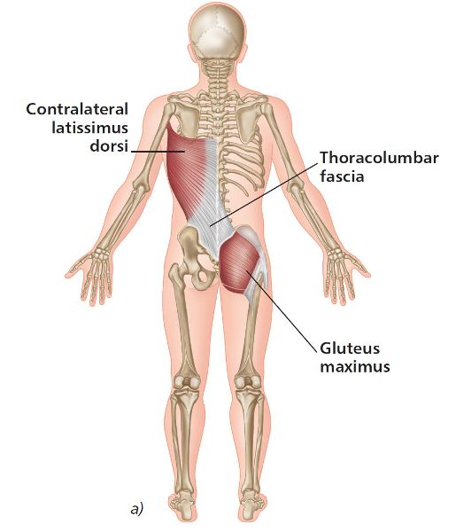
Figure 6.2. (a) Posterior oblique sling.
The force transmitted through the osteo-articular-ligamentous structures induces “form closure” of the spinal facet joints and rotation in the lumbar spine; coupled with a lateral flexion moment, the spinal engine initiates and selects the gears to drive the pelvis into a forward rotation. The induced lumbar rotation effectively stores elastic energy in the spinal ligaments and the annulus fibroses of the intervertebral discs, and it is this return of energy that drives gait.
In order to return the energy, the spine must be stabilized from above: this is accomplished via contralateral arm swing and trunk rotation produced by the contralateral Gmax and latissimus dorsi involvement. The coupling patterns of the spine have evolved to facilitate the return of this force. The counter-rotation is considered to be recruited directly from the spine and not from the legs.
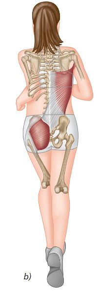
Figure 6.2. (b) Posterior oblique sling utilized whilst running.
Spinal Mechanics Explained
Each and every patient, especially from a spinal mechanics point of view, should be assessed on the basis that they are unique, especially since some people present with vertebral anomalies, which may cause abnormal physiological movement. The following information relating to spinal physiological movement is based on empirical experience rather than on scientific theory; however, it is dependable and useful in helping the budding therapist to understand what they should expect to palpate in the majority of people.
By developing good hand–eye coordination and tactile tissue tension sense, it is certainly possible to detect spinal lesions or, in modern terms, somatic spinal dysfunctions. These dysfunctions can be palpated as abnormal vertebral positioning; they function either statically or dynamically, while surrounding abnormal soft tissue texture is a common feature. Once the somatic spinal dysfunctions have been identified and appropriately treated, the offending vertebral segment(s) can then be re-evaluated to determine whether the treatment approach has been successful. This whole process can be demonstrated clinically, provided that the underpinning knowledge of basic spinal physiological movement has been studied and put into practice by the practitioner.
Fryette’s Laws basically consist of three laws (originally known as principles) pertaining to spinal positioning. The first two laws were developed by Fryette in 1918, and the third law by C.R. Nelson in 1948. The laws are defined as a set of guiding principles that can be used by appropriately trained practitioners to discriminate between dysfunctions that are present within the axial skeleton.
The first two laws only relate to the thoracic and lumbar vertebrae, and the motion available is only considered to be governed by the patterns of force generated by the intervertebral discs, ligaments, and associated musculature. On the other hand, cervical spine motion, which is not classified as a motion that follows Fryette mechanics, is mainly determined by the orientation of the facet joints. We can, however, describe the cervical spine motion as Fryette-like mechanics because of the similarity.
Law 1: Neutral Mechanics—Type I
Neutral mechanics relates to standing or sitting in a relaxed upright position, with normal neutral spinal curves. But what is neutral? Neutral in the world of spinal mechanics is not defined as a single point, but rather as a range in which the weight of the trunk is borne on the vertebral bodies and intervertebral discs, and the facet joints are in an idle state.
Fryette wrote: “Neutral is defined to mean the position of any area of the spine in which the facets are idling, in the position between the beginning of flexion and the beginning of extension.”
This basically means that in neutral, the facet joints are neither in a state of extension (closed) nor in a state of flexion (open)—they are simply idling or resting between these two positions.
According to Fryette, when the spine is in a neutral position, side bending to one side will be accompanied by horizontal rotation to the opposite side: this is referred to as Type I spinal mechanics (Figure 6.3). This first law is observed in what is known as a Type I spinal dysfunction, where more than one vertebra is out of alignment and cannot be returned to neutral by flexion or extension of the vertebrae. The group of vertebrae in question demonstrates a coupled relationship: when side bending forces are induced in a group of typical vertebrae to one side, the entire group will rotate to the opposite side, in other words obeying Type I or Law 1 spinal mechanics. This spinal motion will produce a convexity similar to a spinal curvature known as a scoliosis.
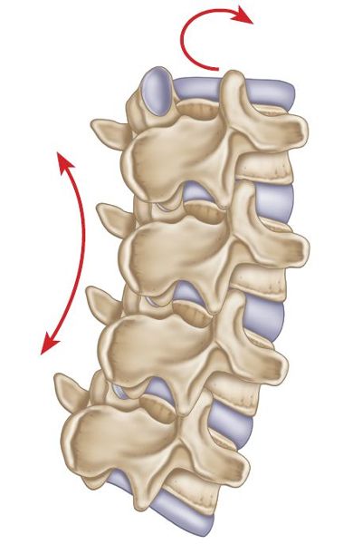
Figure 6.3. Type I spinal mechanics—side bending left, rotation right.
Type I (neutral) dysfunctions generally occur in groups of vertebrae, for example T1–7, and are typically seen in spinal conditions such as scoliosis. The vertebrae of a Type I dysfunction tend to compensate for a single Type II dysfunction, and are usually at the beginning or the end of the group dysfunction, although the dysfunction can sometimes be located at the apex of the curvature.
Another way of looking at Type I spinal mechanics is as follows. In the neutral position for the thoracic and lumbar spines, side bending will create a concavity to the same side as the side bend and a convexity to the side of the rotation (opposite side). For example, side bending to the left will create a concave curve on the left side of the body and a convex curve on the right side.
Note: Neutral spinal mechanics is a naturally occuring motion of the the spine that is required to promote Gracovetsky’s spinal engine, due to the side bending and rotation to the opposite side. Any spinal dysfunction that are present will reduce the overall effciency of the ‘engine’ (spinal).
Law 2: Non-Neutral Mechanics—Type II
Fryette states that when the spine is in a position of flexion or extension, by either standing or sitting while in a forward- or backward-bent position (also known as non-neutral), side bending to one side will be accompanied by rotation to the same side: this is referred to as Type II mechanics (Figure 6.4).
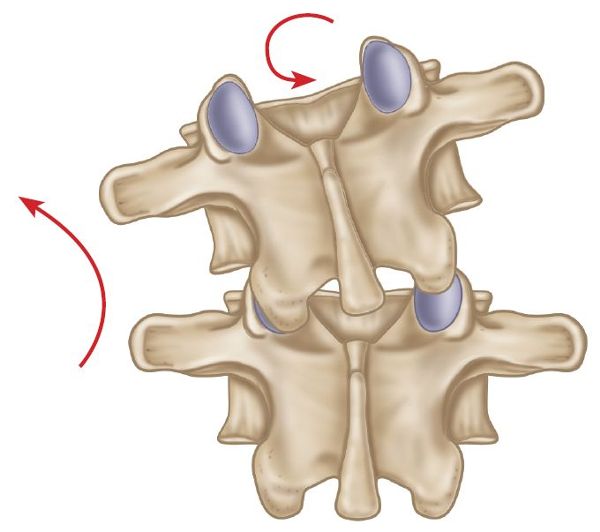
Figure 6.4. Type II spinal mechanics—side bending left, rotation left.
This second law is observed in Type II spinal dysfunctions, where only one vertebral segment is restricted in motion, and becomes much worse in a position of flexion or extension. As mentioned above, there will be a coupled spinal motion, with side bending and rotation in the same direction when this dysfunction is present.
Let’s look at this from another angle. Put simply, if the thoracic or lumbar spine is sufficiently forward or backward bent, the coupled motions of side bending and rotation of a single vertebral unit will occur in the same direction (i.e. to the same side).
Type II (non-neutral) spinal dysfunctions are generally thought to occur in a single vertebral segment. However, two Type II dysfunctions can appear next to each other at the same time, but the occurrence of more than two is rare.
Law 3
According to Nelson (1948), when motion is introduced in one plane, the motion in the other two planes is modified (reduced). The third law basically sums up the first two laws: it simply states that dysfunction in one plane of motion will reduce the motion in all other planes. For example, if rotation is restricted, then side bending and flexion/extension will also be restricted.
Viewing Perspective
When assessing for spinal movement, the spine is usually viewed from behind. Generally speaking, a spinal dysfunction exists when we try to place the patient’s spine in a neutral position, but this position of symmetry cannot to be achieved; the likely reason for this is a dysfunction of either a group of vertebrae or a single spinal segment.
It is possible to detect an abnormal ROM of the spine when patients perform flexion, extension, side bending, and rotation in the cardinal planes; one should be able to see if there is a restricted ROM.
The following sections detail the specific spinal mechanic motion for each of the areas of the vertebral column. I have already explained the term neutral (i.e. the facet joints are idling between flexion and extension), so this position is termed neutral mechanics. By contrast, the term non-neutral mechanics generally refers to either a spinal position of forward bending (flexion) or a spinal position of backward bending (extension).
1. Lumbar Spine
Neutral Mechanics: Type I
When side bending to one side, the vertebral bodies rotate to the opposite side.
Non-Neutral Mechanics: Type II
When side bending to one side, the vertebral bodies rotate to the same side.
Exceptions to the Rule: 5th Lumbar Vertebra (L5)
In neutral mechanics, during side bending to one side the 5th lumbar vertebra (L5) may rotate to either the opposite side or the same side (obeying non-neutral mechanics, even though the spine is in a relatively neutral position) whenever there is some asymmetry/dysfunction of the sacral base or if there are facet joint anomalies present.
2. Thoracic Spine
Neutral Mechanics—Type I
When side bending to one side, the vertebral bodies rotate to the opposite side.
Non-Neutral Mechanics—Type II
When side bending to one side, the vertebral bodies rotate to the same side.
3. Cervical Spine
As mentioned earlier, spinal motion in the cervical spine is mainly determined by the orientation of the facet joints and does not come within the realm of Fryette’s laws; however, we can say these mechanics are Fryette-like, because the motion is similar.
Occipitoatlantal Joint
The occipitoatlantal joint (OAJ) connects the occipital bone to the atlas and always follows Type I (like) mechanics: in side bending to one side, the occiput rotates to the opposite side, independent of whether the occiput is in a neutral or a non-neutral position (flexion or extension).
Atlantoaxial Joint C1/C2
The atlantoaxial joint (AAJ), which lies between the atlas and the axis, is mainly considered to only rotate. There has been some discussion suggesting that, in either neutral or non-neutral mechanics, during side bending movements the atlas (C1) is capable of rotating to either side. Dysfunctions typically found at this level are thought to consist mainly of a rotational component.
The level of C2–C6 in the cervical spine is believed to only follow Type II (like) mechanics, in that side bending and the rotation are always coupled to the same side, regardless of whether the cervical spine is in a neutral position or a non-neutral position (flexion or extension).
C2–C6: Neutral Mechanics
When side bending to one side, the vertebral bodies rotate to the same side, i.e. Type II-like mechanics.
C2–C6: Non-Neutral Mechanics
When side bending to one side, the vertebral bodies rotate to the same side, i.e. Type II-like mechanics.
C7 has facet joints that are orientated in a similar way to the thoracic spine, so this spinal level will follow the classic law of Fryette.
Spinal Mechanics: Definitions
The specific position of a vertebra can be referred to in two different ways:
1. The position of the vertebra, relative to the vertebra below.
2. The direction of the motion restriction of the vertebra, relative to the vertebra below.
In other words, the same vertebral segment can be described from two different points of view.
For example, let’s say T4 (4th vertebra of the thoracic spine) is fixed in an extended, side-bent right, and rotated-right position. This simply means that the T4 is fixed in a position of extension, side bend, and rotation, all to the right side, on top of the vertebra immediately below, i.e. T5. This is because the right T4 inferior facet is fixed in a closed position on the superior facet on T5. The motion restriction has to be in forward flexion as well as in left side bending and left rotation (opposite to the fixed position). This type of dysfunction obeys Type II mechanics, as already explained earlier; however, taking it a stage further, we would now classify the spinal dysfunction as a T4 extension, rotation, side bend right, or T4 ERS(R), which will be discussed shortly.
In terms of diagnosing somatic spinal dysfunction, the positional diagnosis is determined and named according to the direction of the vertebra that has the easiest motion. Let’s take a look at what I mean by that in more detail.
Spinal dysfunction is typically described as either extended or flexed, with a rotation and a side bending component to the same side, or possibly to the opposite side, as you will read later.
Before we define the terminology for spinal dysfunctions, we first need to confirm the presence of a spinal dysfunction by ascertaining the specific position and motion of the vertebra being tested. We can establish this by asking our patient to adopt three different positions of the vertebral column: neutral, extension, and flexion. The vertebral position through palpation simply becomes either symmetrical (level) or asymmetrical (not level) in these three positions, depending on the type of spinal dysfunction/facet restriction present at the time.
If there are no facet restrictions present, when you forward bend your spine, the left and right facet joints (top vertebra in relation to the bottom vertebra) will slide forward in a superior and anterior direction to open; conversely, when you backward bend your spine, the left and right facet joints will slide backward in an inferior and posterior direction to close. However, if the facet joints are for some reason restricted in either a flexion or an extension position, the restricted joint will now act as a pivot point, especially when performing the spinal motion of forward and backward bending.
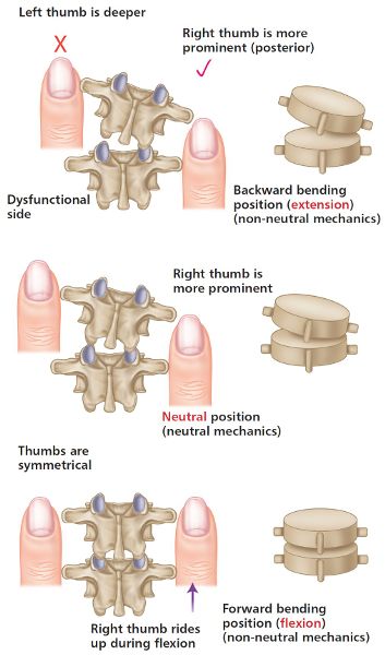
To illustrate this, ask your patient to adopt a neutral position (normally a sitting position, for the thoracic spine) and lightly place your left and right thumbs on the T4/5 transverse process (TP). Lightly palpate for a few seconds and compare the left and right TPs to see if there is any asymmetry; if so, you have now identified the presence of a spinal dysfunction—in a very simple way, you have located a facet restriction. For instance, if the left thumb, while in contact with the left TP, appeared to palpate shallow (i.e. the TP feels closer to the surface of the skin), whereas the right thumb (on the right TP) palpated deep (i.e. the thumb traveled further to reach the right TP), this would be indicative of the T4 vertebra (superior) having rotated to the left side on the T5 vertebra (inferior) below, as shown in Figure 6.5(c).
What this does not tell you, however, is whether the left facet joint is fixed in a closed position or whether the right facet joint is fixed in an open position. That is why it is necessary to palpate the TPs in the position of spinal extension (backward bending) and spinal flexion (forward bending) in order to confirm or discount the presence of a fixed closed facet joint or a fixed open facet joint.
Let’s try to look at this concept in a relatively simple way (I hope) by using the thoracic T4/5 as an example. As already discussed above, we should now know that when the patient is in a neutral position, the T4 vertebra has rotated to the left side, because the left TP palpated as shallow (more prominent) and the right TP palpated as deep (less prominent). From the neutral position, we now ask our patient to forward bend, while the thumbs are still in contact with the TPs; you notice the left and right TPs in the forward-bent position become more asymmetrical (the TP on one side becomes more prominent, and the TP on the other less prominent).
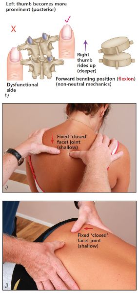
Imagine just for a moment that you consider the left thumb to feel more prominent (think of it as a bump) and now the right thumb feels even deeper (less prominent); this must mean that the left facet joint is fixed in a closed position on the left side, as shown in Figure 6.5(i). Why? When the patient forward bends, the right facet joint is free to glide anteriorly as normal, but the left facet joint is now fixed posteriorly; because the left facet cannot open normally during forward bending, the left facet joint that is fixed in a closed position becomes a pivot point. Because of this pivot, one could say that the right facet basically has to open even more during forward bending, but ends up rotating around the left fixed facet joint that cannot open; this is why the left and right thumbs appear even more asymmetric. In this case the left thumb has become more prominent (the bump increases because the left TP is fixed posteriorly) in the forward-bent position.
When you ask the patient to adopt a position of extension, the thumbs will now palpate level (symmetric), because the left facet joint is already fixed posteriorly in a closed position, and the right facet joint simply continues its natural motion of closing. The left and right thumb positions on the TPs therefore become symmetric (level) in extension (the bump on the left TP disappears), as shown in Figure 6.5(f).
Consider now another type of dysfunction—the case where the right facet joint is fixed in an open position. When we palpate the T4/5 TP in neutral, we will still notice the left thumb is shallow (bump) and the right thumb is deeper, indicating a left rotation, as shown in Figure 6.9(c). However, when the patient forward bends their spine, the thumbs now become symmetric (i.e. the thumbs are now level and the bump disappears), as shown in Figure 6.9(i). By contrast, when the patient backward bends their spine, you notice that the thumbs become asymmetric (i.e. symmetry is lost in extension—the bump felt by the left thumb on the TP increases), as shown in Figure 6.9(f). This time the left thumb actually appears more prominent (bump present), and the right thumb appears to travel deeper in the backward-bent position. Why? In a forward-bent position, both of the facet joints are able to open as normal, hence the thumbs becoming level in this position; however, in a backward-bent position of extension, because the right facet is fixed in an open position (even though it has rotated to the left side), the facet joint cannot close on the right side, but the fixed pivot point created by the right open facets keeps the right TP fixed anteriorly. Since the backward bending motion causes the left side to move more posteriorly, the left TP appears to move further into left rotation. The thumbs therefore appear asymmetric and now, in the backward-bent position, the left thumb on the left TP becomes more prominent (bump appears) than the right thumb.
Note: The above dysfunction relates to the right facet joint fixed in an open position. This is called an FRS(L) as you will read shortly.
One way of remembering these two processes, as it will help you with your own patients, is to understand the following two rules:
Rule 1: In forward bending, if the prominent TP becomes even more prominent (bump appears), then that side is fixed closed.
Rule 2: In backward bending, if the prominent TP becomes more prominent (bump appears), then the opposite side is fixed open.
Maitland (2001) offers another explanation, which might help you better understand what I am trying to say. First, you determine rotation in a neutral position. Then, keeping your thumbs on the TPs of the rotated vertebra, forward and backward bend your client, and feel and watch what happens under your thumbs. Look for the position where the bump (the posterior or prominent vertebra TP of the rotated vertebra) disappears. Maitland says that the position where the bump disappears (or vertebral derotation appears to occur) is the position in which the facets are restricted:
“If the bump disappears in forward bending, the facets are fixed in the forward-bent position, which means the facets are fixed open (flexion fixed).”
“If the bump disappears in back bending, the facets are fixed in the back bent position, which means the facets are fixed closed (extension fixed).”
We will now look at some of the typical terminology that practitioners use in their clinics, along with a few common examples of spinal dysfunctional patterns that patients might present with in your own clinic. Hopefully, once you have read all the information in this chapter, and practiced all the necessary spinal positions in order to confirm or discount the presence of either a fixed facet or an open facet, we can look at some form of treatment strategy, especially for the lumbar spine (discussed in Chapter 13). Specific treatment for the area of the thoracic spine, however, is not covered in this text, even though I have given some examples of the assessment process. Nevertheless, one should be able to modify the treatment techniques shown for the lumbar spine in Chapter 13 and adapt/apply them to dysfunctions in the thoracic spine.
Definition: An extension, rotation, side bending (ERS) dysfunction involves a facet joint (inferior and superior component) which is fixed in a closed position. It is classified as a non-neutral (Type II) spinal mechanics dysfunction.
Extension, Rotation, Side Bending Left—ERS(L)
This is a situation in which the left facet joint is fixed in a closed position.
ERS(L) refers to the orientation of an uppermost vertebra that is fixed in an extended, side-bent, and rotated position to the left side, as shown in Figure 6.5(a).
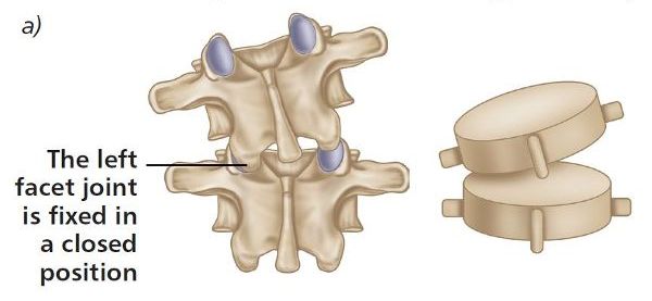
Figure 6.5. (a) Extension, rotation, side bending left—ERS(L).
Two examples will be considered: in the first, the 4th thoracic vertebra (T4) is assumed to be fixed in a closed position on the left side on the 5th thoracic vertebra (T5); in the second, the 5th lumbar vertebra (L5) is assumed to be fixed in a closed position on the left side on the 1st sacral vertebra (S1). We will now test the levels of T4/5 and L5/S1 in the three positions of neutral, flexion, and extension.
Neutral Position
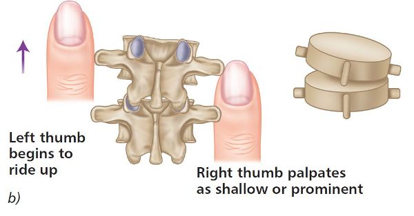
With the patient in a neutral position, place your thumbs approximately 1” (2.5cm) lateral to the T4 and T5 spinous processes, so that the thumbs are in gentle contact with the left and right TPs (repeat the same process when you are ready to do the L5/S1 vertebrae). If there is an ERS(L) present, you will notice that the left thumb appears to be more prominent (shallow) and the right thumb appears to be deeper in the neutral position (see Figure 6.5(b–d)), indicating that the vertebra has rotated to the left side.
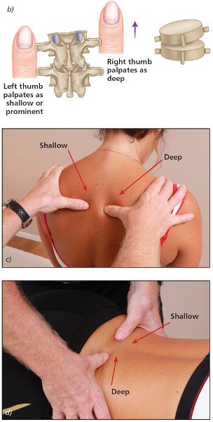
Figure 6.5. (b) Neutral position—the left thumb appears shallow and the right thumb appears deeper, indicating a left rotation of the vertebra. (c) Thoracic spine T4/5. (d) Lumbar spine L5/S1.
Extension Position
As the patient backward bends, observe the relative levels of your thumbs. You will notice that the left and right thumbs are level, as shown in Figure 6.5(e–g).
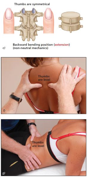
Figure 6.5. (e) Extension position—the left and right thumbs now appear to become level. (f) Thoracic spine T4/5. (g) Lumbar spine L5/S1.
Flexion Position
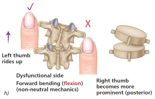
Next look at the relative positions of your thumbs as the patient forward bends. This time you will notice that the left thumb appears to become more prominent (bump appears) and that the right thumb appears to travel deeper, as shown in Figure 6.5(h–j). This asymmetric positioning of the thumbs indicates a fixed closed facet joint on the left side.
Figure 6.5. (h) Flexion position—the left thumb appears more prominent and the right thumb appears deep, indicating a fixed closed vertebra on the left side. (i) Thoracic spine T4/5. (j) Lumbar spine L5/S1.
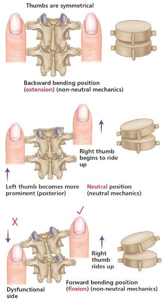
Figure 6.6. Thumb positions for ERS(L).
Extension, Rotation, Side Bending Right—ERS(R)
This is a situation in which the right facet joint is fixed in a closed position.
ERS(R) refers to the orientation of an uppermost vertebra that is fixed in an extended, side-bent, and rotated position to the right side, as shown in Figure 6.7(a).
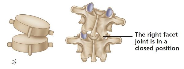
Figure 6.7. (a) Extension, rotation, side bending right—ERS(R).
Two examples will be considered: in the first, T4 is assumed to be fixed in a closed position on the right side on T5; in the second, L5 is assumed to be fixed in a closed position on the right side on S1. We will now test the levels of T4/5 and L5/S1 in the three positions of neutral, flexion, and extension.
Neutral Position
With the patient in a neutral position, place your thumbs approximately 1” (2.5cm) lateral to the T4 and T5 spinous processes, so that the thumbs are in gentle contact with the left and right TPs (repeat the same process when you are ready to do the L5/S1 vertebra). If there is an ERS(R) present, you will notice that the right thumb appears to be shallow and the left thumb appears to be deeper in the neutral position (see Figure 6.7(b–d)), indicating a right rotation of the vertebra.
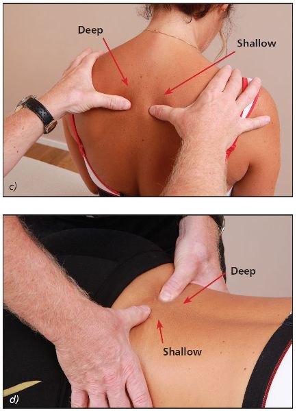
Figure 6.7. (b) Neutral position—the right thumb appears more prominent and the left thumb appears deeper, indicating a right rotation of the vertebra. (c) Thoracic spine T4/5. (d) Lumbar spine L5/S1.
Extension Position
As the patient backward bends, observe the relative levels of your thumbs. You will notice that the left and right thumbs are level, as shown in Figure 6.7(e–g).
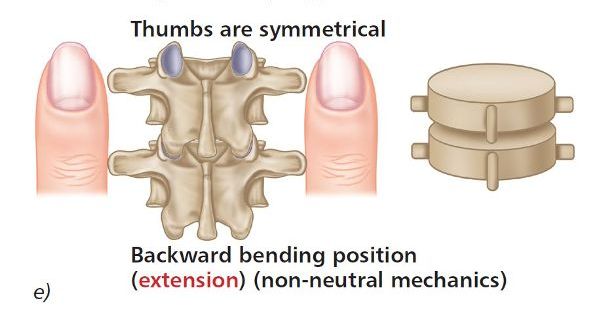
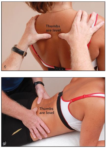
Figure 6.7. (e) Extension position—the left and right thumbs now appear to become level. (f) Thoracic spine T4/5. (g) Lumbar spine L5/S1.
Flexion Position
Next look at the relative level of your thumbs as the patient forward bends. You will notice that the right thumb appears to become more prominent (bump appears) and the left thumb appears to travel deeper, as shown in Figure 6.7(h–j). This asymmetric positioning of the thumbs indicates a fixed closed facet joint on the right side.
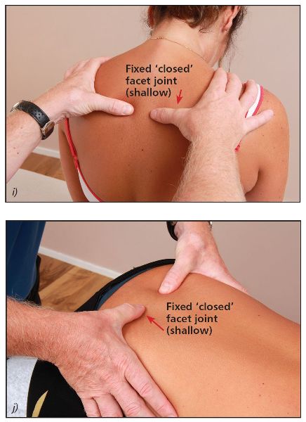
Figure 6.7. (h) Flexion position—the right thumb appears more prominent and the left thumb appears deeper, indicating a fixed closed vertebra on the right side. (i) Thoracic spine T4/5. (j) Lumbar spine L5/S1.
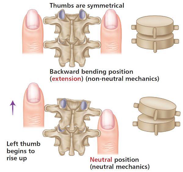
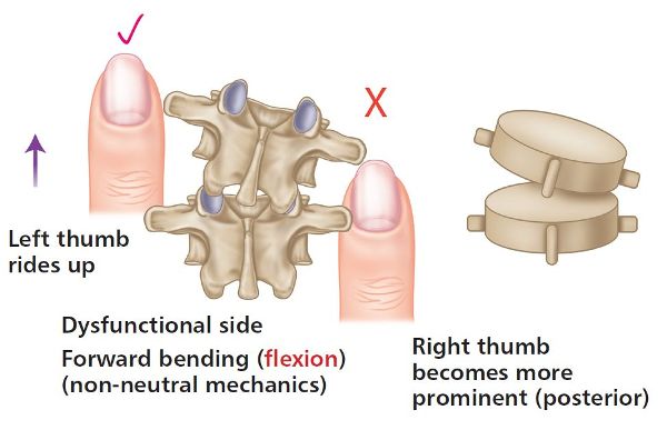
Figure 6.8. Thumb positions for ERS(R).
Definition: A flexion, rotation, side bending (FRS) dysfunction involves a facet joint which is fixed in an open position. It is classified as a non-neutral (Type II) spinal mechanics dysfunction.
Flexion, Rotation, Side Bending Left—FRS(L)
This is a situation in which the right facet joint is fixed in an open position.
Note that, although the dysfunction is to the right facet, FRS(L) refers to the orientation of an uppermost vertebra that is fixed in a flexed, side-bent, and rotated position to the left side. It is the right facet, however, that is dysfunctional, because it is fixed in an open position, as shown in Figure 6.9(a).
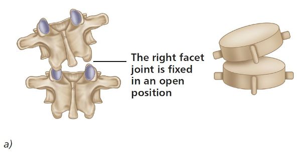
Figure 6.9. (a) Flexion, rotation, side bending left—FRS(L).
We will now test the levels of T4/5 and L5/S1 in the three positions of neutral, flexion, and extension.
Neutral Position
With the patient in a neutral position, place your thumbs approximately 1” (2.5cm) lateral to the T4 and T5 spinous processes, so that the thumbs are in gentle contact with the left and right TPs (repeat the same process when you are ready to do the L5/S1 vertebra). If there is an FRS(L) present, you will notice that the left thumb appears to be more prominent and the right thumb appears to be deeper in the neutral position (see Figure 6.9(b–d)), indicating that the vertebra has rotated to the left side.
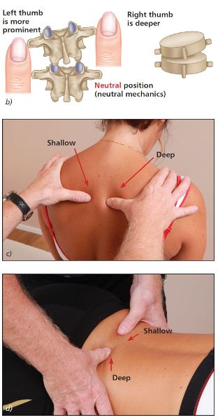
Figure 6.9. (b) Neutral position—the left thumb appears shallow and the right thumb appears deeper, indicating a left rotation of the vertebra. (c) Thoracic spine T4/5. (d) Lumbar spine L5/S1.
Extension Position
As the patient backward bends, observe the relative position of your thumbs. You will notice that the left thumb appears to become more prominent (bump appears) and the right thumb appears to travel deeper, as shown in Figure 6.9(e–g). This asymmetric positioning of the thumbs indicates a fixed open facet joint on the right side (side opposite to rotation).
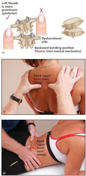
Figure 6.9. (e) Extension position—the left thumb appears more prominent and the right thumb appears deeper, indicating a fixed open facet joint on the right side. (f) Thoracic spine T4/5. (g) Lumbar spine L5/S1.
Flexion Position
Next look at the relative position of your thumbs as the patient forward bends. You will notice that the left and right thumbs are now level, as shown in Figure 6.9(h–j).
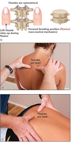
Figure 6.9. (h) Flexion position—the left and right thumbs now appear to become level. (i) Thoracic spine T4/5. (j) Lumbar spine L5/S1.
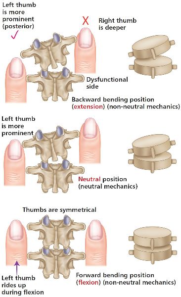
Figure 6.10. Thumb positions for FRS(L).
Flexion, Rotation, Side Bending Right—FRS(R)
This is a situation in which the left facet joint is fixed in an open position.
Note that, although the dysfunction is to the left facet, FRS(R) refers to the orientation of an uppermost vertebra that is fixed in a flexed, side-bent, and rotated position to the right side. It is the left facet, however, that is dysfunctional, because it is fixed in an open position, as shown in Figure 6.11(a).
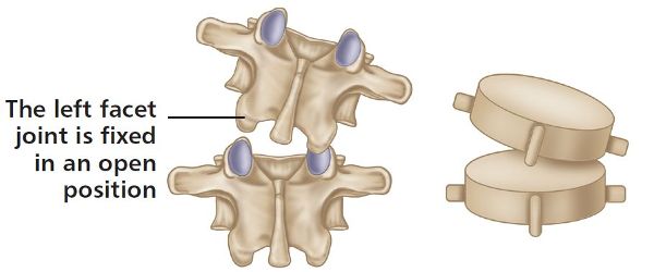
Figure 6.11. (a) Flexion, rotation, side bending right—FRS(R).
We will now test the levels of T4/5 and L5/S1 in the three positions of neutral, flexion, and extension.
Neutral Position
With the patient in a neutral position, place your thumbs approximately 1” (2.5cm) lateral to the T4 and T5 spinous processes, so that the thumbs are in gentle contact with the left and right TPs (repeat the same process when you are ready to do the L5/S1 vertebra). If there is an FRS(R) present, you will notice that the left thumb appears to be shallow and the right thumb appears to be deeper in the neutral position (see Figure 6.11(b–d)), indicating that the vertebra has rotated to the left side.
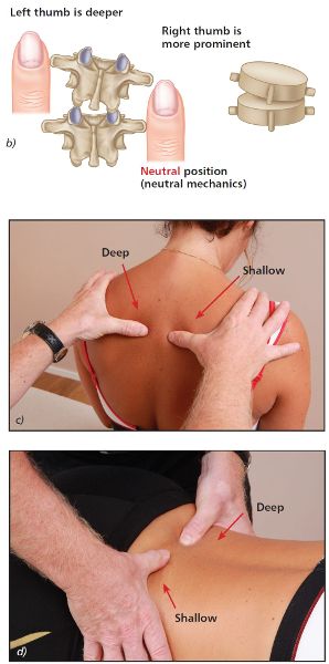
Figure 6.11. (b) Neutral position—the right thumb appears shallow and the left thumb appears deeper, indicating a right rotation of the vertebra. (c) Thoracic spine T4/5. (d) Lumbar spine L5/S1.
Extension Position
As the patient backward bends, observe the relative position of your thumbs. You will notice that the right thumb appears to become more prominent (bump appears) and the left thumb appears to travel deeper, as shown in Figure 6.11(e–g). This asymmetric positioning of the thumbs indicates a fixed open facet joint on the left side (side opposite to rotation).
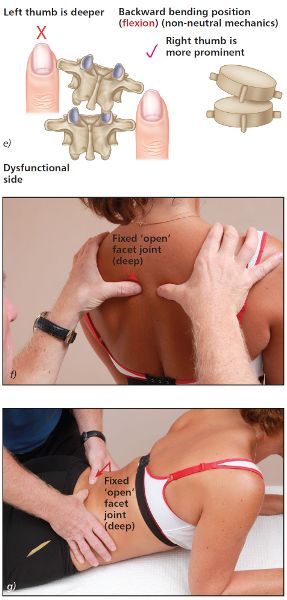
Figure 6.11. (e) Extension position—the right thumb appears more prominent and the left thumb appears deeper, indicating a fixed open facet joint on the left side. (f) Thoracic spine T4/5. (g) Lumbar spine L5/S1.
Flexion Position
Next look at the relative position of your thumbs as the patient forward bends. You will notice that the left and right thumbs are now level, as shown in Figure 6.11(h–j).
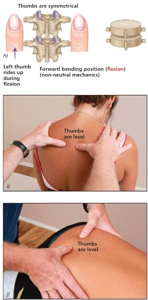
Figure 6.11. (h) Flexion position—the left and right thumbs now appear to become level. (i) Thoracic spine T4/5. (j) Lumbar spine L5/S1.
Definition: A neutral mechanics (Type I) dysfunction of a group of vertebrae (NR) typically involves a group of three or more vertebrae, and the side bending is considered to be the primary motion restriction, with a secondary rotational component. As explained earlier, this dysfunction produces a concavity on the same side as the side bending, and a convexity on the side of the rotation. This type of dysfunction is considered to be a compensatory group dysfunction as a result of a primary dysfunction; the primary dysfunctions are usually an FRS or ERS. The vertebrae in question side bend to one side and rotate to the opposite side.
Group Neutral Dysfunction, Rotation Left—NR(L)
This is a situation involving at least three vertebrae, which are side bent to the right and rotated to the left.
The rotation to the left is maintained throughout the range of backward bending, neutral, and forward bending, as shown in Figure 6.13. The amount of rotation may vary a little throughout this ROM, and will most likely be maximal in the neutral position.

Figure 6.13. Neutral dysfunction—side bending right, rotation left—NR(L).
Group Neutral Dysfunction, Rotation Right—NR(R)
This is a situation involving at least three vertebrae, which are side bent to the left and rotated to the right.
The rotation to the right is maintained throughout the range of backward bending, neutral, and forward bending, as shown in Figure 6.14. The amount of rotation may vary a little throughout this ROM, and will most likely be maximal in the neutral position.

Figure 6.14. Neutral dysfunction—side bending left, rotation right—NRR
