EXPERIMENTING WITH
GRIPPER DESIGNS
GRIPPER DESIGNS
The arm system detailed in Chapter 27 isn’t much good without hands. In the robotics
world, hands are usually called grippers (also end effectors) because the word more
closely describes their function. Few robotic hands can manipulate objects with the fine
motor control of a human hand; they simply grasp or grip an object, hence the name gripper.
See Fig. 28-1 for an example.
Gripper designs are numerous, and no one single design is ideal for all applications.
Each gripper technique has unique advantages over the others, and you must fit the gripper
to the application at hand (pun intended). This chapter outlines a number of useful
gripper designs for your robots. Most are fairly easy to build; some even make use of inexpensive
plastic toys. The gripper designs encompass just the finger or grasping mechanisms.
The last section of this chapter details how to add wrist rotation to any of the gripper
designs.
The clapper gripper is a popular design, favored because of its easy construction and simple
mechanics. You can build the clapper using metal, plastic, wood, or a combination of all
three. The parts list inTable 28-1 is for the parts used to build the metal and plastic clapper
shown in Fig. 28-2
2 |
1  -by-2-by- -by-2-by- -in thick acrylic plastic sheet -in thick acrylic plastic sheet |
2 |
1-by-  -in corner angle bracket -in corner angle bracket |
1 |
1 -by-1-in brass or aluminum hinge |
1 |
Small 6- or 12-vdc spring-loaded solenoid |
8 |
-in-by- stove bolts, nuts stove bolts, nuts |
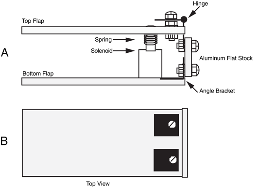
The clapper consists of a wrist joint (which, for the time being, we'll assume is permanently
attached to the forearm of the robot). Connected to the wrist are two plastic plates. The
bottom plate is secured to the wrist; the top plate is hinged. A small spring-loaded solenoid
is positioned inside, between the two plates. When the solenoid is not activated, the spring
pushes the two flaps out, and the gripper is open. When the solenoid is activated, the plunger
pulls in, and the gripper closes. The amount of movement at the end of the gripper is
minimal—about  in with most solenoids. However, that is enough for general gripping tasks.
in with most solenoids. However, that is enough for general gripping tasks.Cut two  -in-thick acrylic plastic pieces to 1 by 2
 in. Attach the lower flap to two
1-by-
in. Attach the lower flap to two
1-by- -in corner angle brackets. Place the brackets approximately
  in from either side of the flap. Secure the pieces using
  -by--in bolts and nuts. Cut a 1-in length of 1-by- -in aluminum bar stock. Mount the two brackets to the bottom of the stock as shown in
the figure. Attach the top flap to a 1-by-1-in (approximately) brass or aluminum miniature
hinge. Drill out the holes in the hinge with a #28 drill to accept bolts. Secure the hinge
using bolts and nuts.
-by--in bolts and nuts. Cut a 1-in length of 1-by- -in aluminum bar stock. Mount the two brackets to the bottom of the stock as shown in
the figure. Attach the top flap to a 1-by-1-in (approximately) brass or aluminum miniature
hinge. Drill out the holes in the hinge with a #28 drill to accept bolts. Secure the hinge
using bolts and nuts.
-in-thick acrylic plastic pieces to 1 by 2 in. Attach the lower flap to two
1-by--in corner angle brackets. Place the brackets approximately in from either side of the flap. Secure the pieces using -by--in bolts and nuts. Cut a 1-in length of 1-by- -in aluminum bar stock. Mount the two brackets to the bottom of the stock as shown in
the figure. Attach the top flap to a 1-by-1-in (approximately) brass or aluminum miniature
hinge. Drill out the holes in the hinge with a #28 drill to accept bolts. Secure the hinge
using bolts and nuts.The choice of solenoid is important because it must be small enough to fit within the
two flaps and it must have a flat bottom to facilitate mounting. It must also operate with
the voltage used in your robot, usually 6 or 12 V. Some solenoids have mounting flanges
opposite the plunger. If yours does, use the flange to secure the solenoid to the bottom
flap. Otherwise, mount the solenoid in the center of the bottom flap, approximately in
from the back end (nearest the brackets), with a large glob of household cement. Let it stand
to dry.
in
from the back end (nearest the brackets), with a large glob of household cement. Let it stand
to dry.Align the top flap over the solenoid. Make a mark at the point where the plunger contacts
the plastic. Drill a hole just large enough for the plunger; you want a tight fit. Insert the
plunger through the hole and push down so that the plunger starts to peek through.
Align the top and bottom flaps so they are parallel to one another.
Using the mounting holes in the hinges as a guide, mark corresponding holes in the aluminum
bar. Drill holes and mount the hinge using -in-by- bolts and nuts.
-in-by- bolts and nuts.Test the operation of the clapper by activating the solenoid. If the plunger works loose,
apply some household cement to keep it in place. You may want to add a short piece of rubber
weather stripping to the inside ends of the clappers so they can grasp objects easier.
You can also use stick-on rubber feet squares, available at most hardware and electronics
stores.
The two-pincher gripper consists of two movable fingers, somewhat like the claw of a lobster.
The steps for constructing one basic and two advanced models are described in this
section.
For ease of construction, the basic two-pincher gripper is made from extra Erector set
parts (the components from a similar construction kit toy may also be used). Cut two metal
girders to 4 in (since this is a standard Erector set size, you may not have to do any cutting).
Cut a length of angle girder to 3 in, as shown in Fig. 28-3 (refer to the parts list in
Table 28-2). Use -by--in bolts and nuts to make two pivoting joints. Cut two 3-in
lengths and mount them (see Fig. 28-4). Nibble the corner off both pieces to prevent the
two from touching one another. Nibble or cut through two or three holes on one end to
make a slot. As illustrated in Fig. 28-5, use -by--in bolts and nuts to make pivoting
joints in the fingers.
in (since this is a standard Erector set size, you may not have to do any cutting).
Cut a length of angle girder to 3 in, as shown in Fig. 28-3 (refer to the parts list in
Table 28-2). Use -by--in bolts and nuts to make two pivoting joints. Cut two 3-in
lengths and mount them (see Fig. 28-4). Nibble the corner off both pieces to prevent the
two from touching one another. Nibble or cut through two or three holes on one end to
make a slot. As illustrated in Fig. 28-5, use -by--in bolts and nuts to make pivoting
joints in the fingers.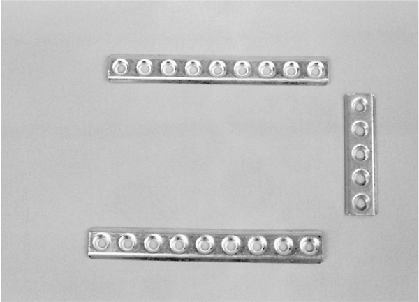
2 |
4 -in Erector set girder |
|
1 |
3 -in-length Erector set girder |
|
4 |
-in-by- stove bolts, fender washer, tooth lock washer, nuts |
|
Misc. |
14- to 16-gauge insulated wire ring lugs, aircraft cable, rubber tabs,
-by--in corner angle brackets (galvanized or from Erector set) |
|
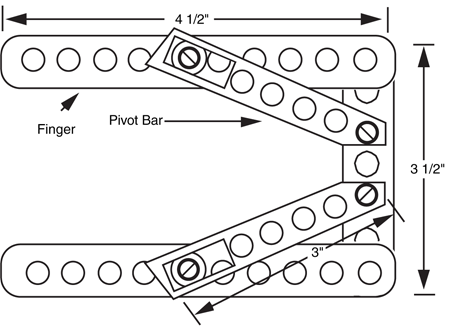
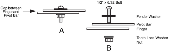
Figure 28-5 Hardware assembly detail of the pivot bar and fingers of the two-pincher
gripper. a. Assembled sliding joint; b. exploded view.
The basic gripper is finished. You can actuate it in a number of ways. One way is to
mount a small eyelet between the two pivot joints on the angle girder. Thread two small
cables or wire through the eyelet and attach the cables. Connect the other end of the cables to a solenoid or a motor shaft. Use a light compression spring to force the fingers apart
when the solenoid or motor is not actuated.
You can add pads to the fingers by using the corner braces included in most Erector set
kits and then attaching weather stripping or rubber feet to the brace. The finished gripper
should look like the one depicted in Fig. 28-6.
You can use a readily available plastic toy and convert it into a useful two-pincher gripper
for your robot arm. The toy is a plastic extension arm with the pincher claw on one end and
a hand gripper on the other (see Fig. 28-7). To close the pincher, you pull on the hand gripper.
The contraption is inexpensive—usually under $10—and it is available at many toy
stores.
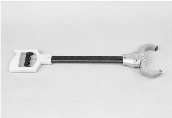
Figure 28-7 A commercially available plastic two-pincher robot arm and claw toy. The gripper
can be salvaged for use in your own designs.
Chop off the gripper 3 in below the wrist. You'll cut through an aluminum cable. Now
cut off another 1 in of tubing—just the arm, but not the cable. File off the arm tube until
it's straight, then fashion a 1-in length of  -in-diameter dowel to fit into the rectangular
arm. Drill a hole for the cable to go through. The cable is off-centered because it attaches
to the pull mechanism in the gripper, so allow for this in the hole. Place the cable through
the hole, push the dowel at least in into the arm, and then drill two small mounting holes
to keep the dowel in place (see Fig. 28-8). Use -by--in bolts and nuts to secure the
pieces.
-in-diameter dowel to fit into the rectangular
arm. Drill a hole for the cable to go through. The cable is off-centered because it attaches
to the pull mechanism in the gripper, so allow for this in the hole. Place the cable through
the hole, push the dowel at least in into the arm, and then drill two small mounting holes
to keep the dowel in place (see Fig. 28-8). Use -by--in bolts and nuts to secure the
pieces.
in of tubing—just the arm, but not the cable. File off the arm tube until
it's straight, then fashion a 1-in length of -in-diameter dowel to fit into the rectangular
arm. Drill a hole for the cable to go through. The cable is off-centered because it attaches
to the pull mechanism in the gripper, so allow for this in the hole. Place the cable through
the hole, push the dowel at least in into the arm, and then drill two small mounting holes
to keep the dowel in place (see Fig. 28-8). Use -by--in bolts and nuts to secure the
pieces.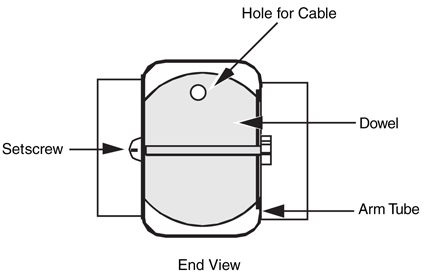
Figure 28-8 Assembly detail for the claw gripper and wooden
dowel. Drill a hole for the actuating cable to pass through.
You can now use the dowel to mount the gripper on an arm assembly. You can use a
small -in U-bolt or flatten one end of the dowel and attach it directly to the arm. The gripper
opens and closes with only a  -in pull. Attach the end of the cable to a heavy-duty solenoid
that has a stroke of at least in. You can also attach the gripper cable to a -in round
aircraft cable. Use a crimp-on connector designed for 14- to 16-gauge electrical wire to
connect them end to end, as shown in Fig. 28-9. Attach the aircraft cable to a motor or
rotary solenoid shaft and activate the motor or solenoid to pull the gripper closed. The spring built into the toy arm opens the gripper when power is removed from the solenoid
or motor.
-in pull. Attach the end of the cable to a heavy-duty solenoid
that has a stroke of at least in. You can also attach the gripper cable to a -in round
aircraft cable. Use a crimp-on connector designed for 14- to 16-gauge electrical wire to
connect them end to end, as shown in Fig. 28-9. Attach the aircraft cable to a motor or
rotary solenoid shaft and activate the motor or solenoid to pull the gripper closed. The spring built into the toy arm opens the gripper when power is removed from the solenoid
or motor.
-in U-bolt or flatten one end of the dowel and attach it directly to the arm. The gripper
opens and closes with only a -in pull. Attach the end of the cable to a heavy-duty solenoid
that has a stroke of at least in. You can also attach the gripper cable to a -in round
aircraft cable. Use a crimp-on connector designed for 14- to 16-gauge electrical wire to
connect them end to end, as shown in Fig. 28-9. Attach the aircraft cable to a motor or
rotary solenoid shaft and activate the motor or solenoid to pull the gripper closed. The spring built into the toy arm opens the gripper when power is removed from the solenoid
or motor.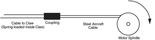
Figure 28-9 One method for actuating the gripper: attach the solid aluminum
cable from the claw to a length of flexible steel aircraft cable. Anchor the cable to a
motor or rotary solenoid. Actuate the motor or solenoid and the gripper closes. The
spring in the gripper opens the claw when power to the motor or solenoid is
removed.
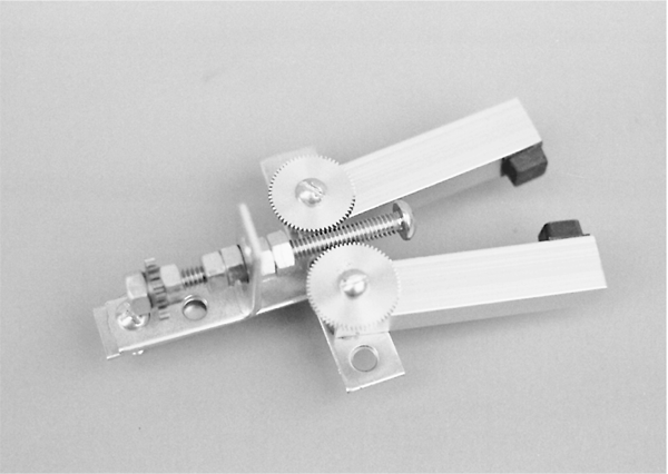
This gripper design (Fig. 28-1) uses a novel worm gear approach, without requiring a hard-to-
find (and expensive) worm gear. The worm is a length of  -in 20 bolt; the gears are standard
1-in-diameter 64-pitch aluminum spur gears (hobby stores have these for about $1
apiece). Turning the bolt opens and closes the two fingers of the gripper. Refer to the parts
list in Table 28-3
-in 20 bolt; the gears are standard
1-in-diameter 64-pitch aluminum spur gears (hobby stores have these for about $1
apiece). Turning the bolt opens and closes the two fingers of the gripper. Refer to the parts
list in Table 28-3
-in 20 bolt; the gears are standard
1-in-diameter 64-pitch aluminum spur gears (hobby stores have these for about $1
apiece). Turning the bolt opens and closes the two fingers of the gripper. Refer to the parts
list in Table 28-32 |
3-in lengths  -by--by--in aluminum channel -by--by--in aluminum channel |
|
2 |
1-in-diameter 64-pitch plastic or aluminum spur gear |
|
1 |
2-in flat mending T |
|
1 |
1 -by--in corner angle iron |
|
1 |
3 -by- -in 20 stove bolt -in 20 stove bolt |
|
2 |
-in 20 locking nuts, nuts, washers, tooth lock washers |
|
2 |
-in-by- stove bolts, nuts, washers stove bolts, nuts, washers |
|
1 |
1-in-diameter 48-pitch spur gear (to mate with gear on driving motor shaft) |
|
Construct the gripper by cutting two 3-in lengths of  -by--by--in aluminum channel
stock. Using a 3-in flat mending T plate as a base, attach the fingers and gears to the T as
shown in Fig. Fig. 28-10. The distance of the holes is critical and depends entirely on the diameter
of the gears you have. You may have to experiment with different spacing if you use
another gear diameter. Be sure the fingers rotate freely on the base but that the play is not
excessive. Too much play will cause the gear mechanism to bind or skip.
-by--by--in aluminum channel
stock. Using a 3-in flat mending T plate as a base, attach the fingers and gears to the T as
shown in Fig. Fig. 28-10. The distance of the holes is critical and depends entirely on the diameter
of the gears you have. You may have to experiment with different spacing if you use
another gear diameter. Be sure the fingers rotate freely on the base but that the play is not
excessive. Too much play will cause the gear mechanism to bind or skip.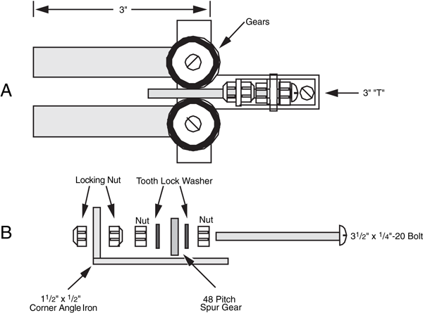
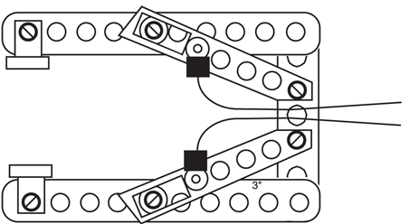
Figure 28-10 A two-pincher gripper based on a homemade work drive system. a. Assembled
gripper; b. worm shaft assembly detail.
Secure the shaft using a 1-by--in corner angle bracket. Mount it to the stem of the T
using an  -by-1-in bolt and nut. Add a #10 flat washer between the T and the bracket to
increase the height of the bolt shaft. Mount a 3-in-long -in 20 machine bolt through the
bracket. Use double nuts or locking nuts to form a free-spinning shaft. Reduce the play as
much as possible without locking the bolt to the bracket. Align the finger gears to the bolt
so they open and close at the same angle.
-by-1-in bolt and nut. Add a #10 flat washer between the T and the bracket to
increase the height of the bolt shaft. Mount a 3-in-long -in 20 machine bolt through the
bracket. Use double nuts or locking nuts to form a free-spinning shaft. Reduce the play as
much as possible without locking the bolt to the bracket. Align the finger gears to the bolt
so they open and close at the same angle.
-by--in corner angle bracket. Mount it to the stem of the T
using an -by-1-in bolt and nut. Add a #10 flat washer between the T and the bracket to
increase the height of the bolt shaft. Mount a 3-in-long -in 20 machine bolt through the
bracket. Use double nuts or locking nuts to form a free-spinning shaft. Reduce the play as
much as possible without locking the bolt to the bracket. Align the finger gears to the bolt
so they open and close at the same angle.To actuate the fingers, attach a motor to the base of the bolt shaft. The prototype gripper
used a -in-diameter 48-pitch spur gear and a matching 1-in 48-pitch spur gear on the drive motor. Operate the motor in one direction and the fingers close. Operate the motor
in the other direction and the fingers open. Apply small rubber feet pads to the inside ends
of the grippers to facilitate grasping objects.
-in-diameter 48-pitch spur gear and a matching 1-in 48-pitch spur gear on the drive motor. Operate the motor in one direction and the fingers close. Operate the motor
in the other direction and the fingers open. Apply small rubber feet pads to the inside ends
of the grippers to facilitate grasping objects.Figs. Fig. 28-11 through Fig. 28-14 show another approach to constructing two-pincher grippers.
By adding a second rail to the fingers and allowing a pivot for both, the fingertips
remain parallel to one another as the fingers open and close. You can employ several actuation
techniques with such a gripper. Fig. Fig. 28-15 shows the gripping mechanism of the
Radio Shack/Tomy Armatron. Note that it uses double rails to effect parallel closure of the
fingers. You can model your own gripper using the design of the Armatron or amputate an
Armatron and use its gripper for your own robot.
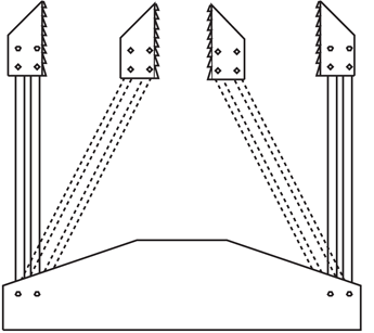
Figure 28-11 Adding a second rail to the fingers
and allowing the points to freely pivot causes the fingertips
to remain parallel to one another.
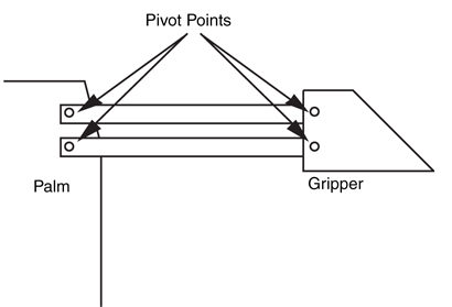
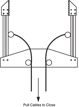
Figure 28-13 A way to actuate the gripper.
Attach cables to the fingers and pull the cables with a
motor or solenoid. Fit a torsion spring along the fingers
and palm to open the fingers when power is
removed from the motor or solenoid.
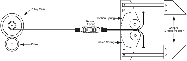
Figure 28-14 Actuation detail of a basic two-pincher gripper using a motor. The tension spring prevents undo pressure on the object being
grasped. Note the torsion springs in the palm of the gripper.
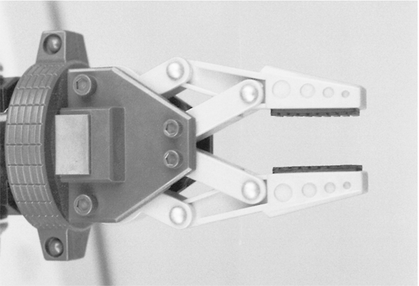
Figure 28-15 A close-up view of the Armatron toy gripper. Note the use of the dual-rail finger
system to keep the fingertips parallel. The gripper is moderately adaptable to your own designs.
Clapper and two-pincher grippers are not like human fingers. One thing they lack is a compliant
grip: the capacity to contour the grasp to match the object. The digits in our fingers
can wrap around just about any oddly shaped object, which is one of the reasons we are
able to use tools successfully.
You can approximate the compliant grip by making articulated fingers for your robot. At
least one toy is available that uses this technique; you can use it as a design base. The plastic toy arm described earlier is available with a handlike gripper instead of a claw gripper.
Pulling on the handgrip causes the four fingers to close around an object, as shown in Fig. 28-16. The opposing thumb is not articulated, but you can make a thumb that moves in a
compliant gripper of your own design.
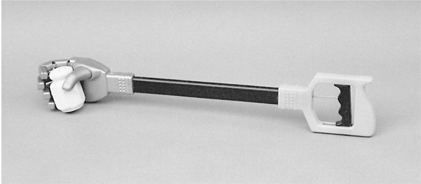
Figure 28-16 Commercially available plastic robotic arm and hand toy. The gripper can be
salvaged for use in your own designs. The opposing thumb is not articulated, but the fingers have a
semicompliant grip.
Make the fingers from hollow tube stock cut at the knuckles. The mitered cuts allow the
fingers to fold inward. The fingers are hinged by the remaining plastic on the topside of the
tube. Inside the tube fingers is semiflexible plastic, which is attached to the fingertips. Pulling
on the handgrip exerts inward force on the fingertips and the fingers collapse at the cut
joints.
You can use the ready-made plastic hand for your projects. Mount it as detailed in the
previous section on the two-pincher claw arm. You can make your own fingers from a variety
of materials. One approach is to use the plastic pieces from some of the toy construction
kits. Cut notches into the plastic to make the joints. Attach a length of 20- or 22-gauge
stove wire to the fingertip and keep it pressed against the finger using nylon wire ties. Do
not make the ties too tight, or the wire won’t be able to move. An experimental plastic finger
is shown in Fig. 28-17.
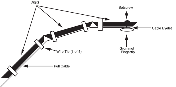
Figure 28-17 A design for an experimental compliant finger. Make the finger spring-loaded
by attaching a spring to the back of the finger (a strip of lightweight spring metal also works).
You can mount three of four such fingers on a plastic or metal “palm” and connect all
the cables from the fingers to a central pull rod. The pull rod is activated by a solenoid or
motor. Note that it takes a considerable pull to close the fingers, so the actuating solenoid
or motor should be fairly powerful.
The finger opens again when the wire is pushed back out as well as by the natural spring
action of the plastic. This springiness may not last forever, and it may vary if you use other
materials. One way to guarantee that the fingers open is to attach an expansion spring, or
a strip of flexible spring metal, to the tip and base of the finger, on the back side. The spring
should give under the inward force of the solenoid or motor, but adequately return the finger
to the open position when power is cut.
The human wrist has three degrees of freedom: it can twist on the forearm, it can rock up
and down, and it can rock from side to side. You can add some or all of these degrees of
freedom to a robotic hand. A basic schematic of a three-degree-of-freedom wrist is shown
in Fig. 28-18.

Figure 28-18 The three basic degrees of freedom in a
human or robotic wrist (wrist rotation in the human arm is
actually accomplished by rotating the bones in the forearm).
With most arm designs, you'll just want to rotate the gripper at the wrist. Wrist rotation
is usually performed by a motor attached at the end of the arm or at the base. When the
motor is connected at the base (for weight considerations), a cable or chain joins the motor
shaft to the wrist. The gripper and motor shaft are outfitted with mating spur gears. You can
also use chains (miniature or #25) or timing belts to link the gripper to the drive motor. Fig. 28-19 shows the wrist rotation scheme used to add a gripper to the revolute coordinate arm
described in Chapter 27.
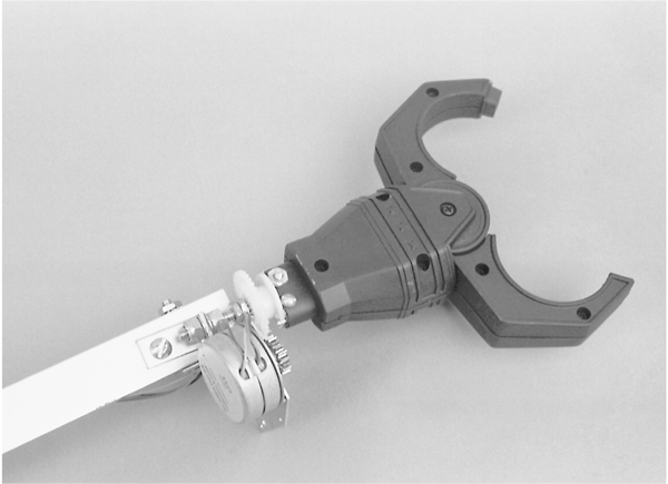
Figure 28-19 A two-pincher gripper (from the plastic toy robotic arm detailed earlier in the
chapter), attached to the revolute arm described in Chapter 27. A small stepper motor and gear
system provide wrist rotation.
You can also use a worm gear on the motor shaft. Remember that worm gears introduce
a great deal of gear reduction, so take this into account when planning your robot. The wrist
should not turn too quickly or too slowly.
Another approach is to use a rotary solenoid. These special-purpose solenoids have a
plate that turns 30° to 50° in one direction when power is applied. The plate is spring-loaded,
so it returns to its normal position when the power is removed. Mount the solenoid
on the arm and attach the plate to the wrist of the gripper.
To learn more about . . . |
Read |
|
Using DC motors and shaft encoders |
Chapter 20, "Working with DC Motors" |
|
Using stepper motors to drive robot parts |
Chapter 21, "Working with Stepper Motors" |
|
Different robotic arm systems and assemblies |
Chapter 26, "Reaching Out with Robot Arms" |
|
Building a robotic revolute coordinate arm |
Chapter 27, "Build a Revolute Coordinate Arm" |
|
Interfacing feedback sensors to computers and microcontrollers |
Chapter 14, "Computer Peripherals" |