CHAPTER 10
Finger Ring
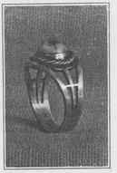
PIERCED RING
PROBLEM 17, fig. 47. The size of the ring must first be determined. This is found by using the ring sizes or by measuring with a narrow strip of paper around the finger on which the ring is to be worn. When this strip of paper is straightened out it will give the length of the metal needed for the ring. Usually a precious or semiprecious stone is made the central feature of the ring. As the size of the stone will determine the width of the ring at the top, it is necessary to know this at the beginning. A variety of methods are used in fastening the stone to the ring, which are called settings. The simplest form, known as a box setting, is employed in the ring illustrated. Not knowing the length of the metal needed and the size of the stone and the kind of setting to be used, a drawing of the design as on page 83, fig. 1, is necessary. Then make a careful tracing, fig. 2, from the drawing and glue it to the surface of the metal, fig. 3, A and B. For the ring here illustrated, No. 18 gauge sterling silver is used, 2¾″ long and  wide. After the glue is thoroughly dry it will hold the tracing firmly in place. A small drill, No. 60, is used to make openings through which the metal saw is placed. For this problem a No. 00 saw is needed as the openings are quite small in places. Saw as closely to the line as possible, being careful not to cut into it. After the openings are sawed out (fig. 4) file them true with the needle files. A square and a knife edge are needed to finish the small openings. Next cut the metal the required length and file the ends square. When the filing is completed and all rough edges are removed it is bent into shape. To do this, bore a hole with a ¾″ bit into a piece of wood about 2″ x 3″ x 2″ as shown on page 83, fig. 5. Saw through the middle of the block on the dotted line. Take a piece of
  ” dowel or a ring arbor and having placed the metal over the block as at fig. 6, strike the upper part of the dowel or arbor with the mallet, driving the metal into the form as at fig. 7. Then striking on the upturned ends as on page 85, fig. 8, first on one side and then on the other, gradually bring them nearer together as at fig. 9, and continue till they touch. Use a piece of binding wire to hold the ends in contact while they are being soldered, fig. 10. After coating the joint with borax and applying a small piece of solder at A, place on the charcoal block for soldering.

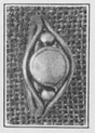
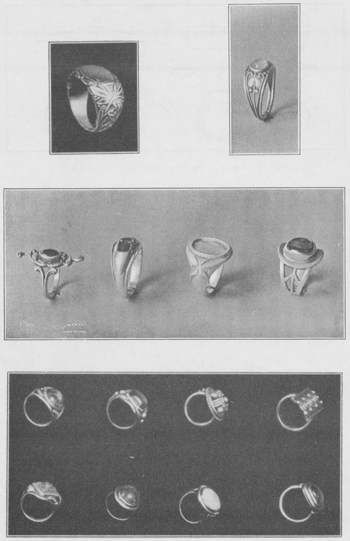
Pierced ring designs, a challenge to able designing, Problem 17
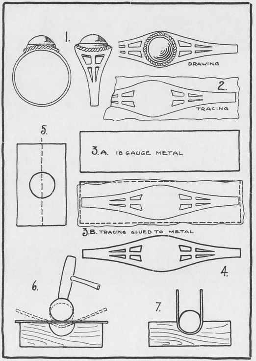
Various steps in making the pierced ring in silver, Problem 17
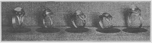
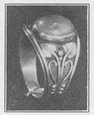
Pierced silver rings set with cabochon stones
The bezel is next made from No. 24 gauge silver and for this ring a strip of metal 1¼″ x ¼″ is needed, fig. 11. After cutting the strip the right width it is bent to fit the stone, cut the right length, and soldered. As this bezel is to fit a convex surface, some filing is necessary to make a good joint, fig. 12A. After fitting the bezel perfectly to the top of the ring, solder in place as at fig. 13. The twist shown in the design is next made. Take a piece of No. 24 gauge silver wire about 12″ long, double it twice and place one end in the vise; with a nail or anything that will serve the purpose, twist the wire as shown at fig. 14. After twisting it from one end to the other, remove it from the vise, coat it with borax and place it on the charcoal block (fig. 15) Put three or four small pieces of solder at equal distances along the wire and heat to the soldering point, allowing the solder to run along the wire. This is done to hold the different strands together so that they will not separate when cut. When this has been done bend the wire about the bezel to get the required size and then cut and solder the ends together, making a ring as at fig. 16. A little filing may be necessary at the joint to work the ends together. Now place it over the bezel as shown on page 83, fig. 1, and solder in place. The ring is next pickled to clean off the borax about the soldered joints. The bezel is filed to the right height, the thickness of the edge reduced and the stone set.
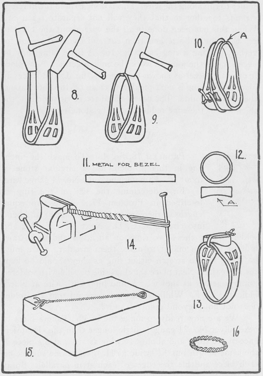
Continuation of steps in making the first ring in silver. Problem 17
WIRE RING
PROBLEM 18, fig. 48. To make the finger ring in this problem use a circular stone of about ¼″ diameter and some No. 14 gauge wire.
First determine the size of the ring as described in Problem 17. Take two equal lengths of the wire as A, B, on page 87 and bend into circles, as C, D. Next file ends flat and solder. Place these two rings on an arbor and use a rawhide or wooden mallet to make them circular. Care must be taken not to stretch either ring as they should be kept the same size. Next place the rings side by side with soldered joints together as shown at E and bind with wire at places indicated by F. While soldering be careful that the solder does not flow beyond points 1 and 2.
We are now ready to make the bezel. Take a piece of bezel silver No. 24 gauge a little longer than the circumference of the stone and about ¼″ wide as at G, also a piece of the same length but  ″ wide as H. Scrape one surface on each piece and file the edges of each strip parallel. Borax the scraped surfaces and place the strip ″ wide upon the strip ¼″ wide with scraped surfaces facing each other (fig. 1) Bind with wire and make sure that edges 1—2, and 3—4 are parallel. Now place small pieces of solder along 3—4 and apply heat from the direction indicated by the arrow in fig. I to draw the solder under the top strip. Do not use too much solder as it will flush the edge upon which the stone is to rest. The angle ought to be kept a right angle like J and not like that indicated by curve in K. The shoulder bezel is now ready to bend around the stone. The method is the same as in former problems. Care must be exercised not to make the bezel too small as any attempt to stretch the metal will result in a piece of bad workmanship.
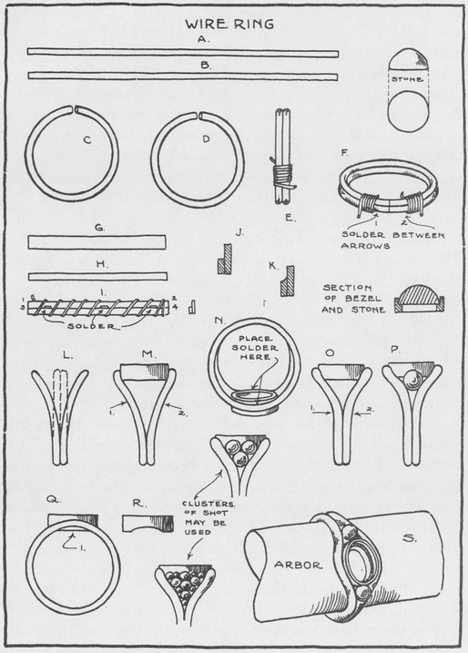
Simple steps produce a ring as Figure 48, Problem 18
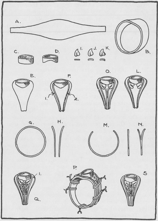
After the bezel is made it is inserted between the rings. The rings are first pulled apart until they can receive the bezel as shown by fig. L. Do not push the bezel too far down into the rings; that indicated by fig. M is about right. No binding is necessary as the spring in the rings will hold the bezel in place while being soldered. It will be easier to solder the bezel to the rings if the whole ring is inverted upon the charcoal block as shown by fig. N. The solder is placed at points indicated by arrows. Again the utmost care must be exercised not to hold the flame too long while the solder comes to the melting point as the weight of the rings may cause them to fall even with the top of the bezel.
Having done this part of the work successfully, we are ready to bring the wire closer together as indicated by arrows at 1 and 2, fig. M. Here it becomes necessary to use the round-nose pliers for part of the work. As they are apt to mar the surface of the wire it is well to wrap a piece of cloth or thin leather around the nose of the pliers. At first, points 1 and 2 of fig. M can be brought together part of the way with the fingers. As a last resort the pliers are used till they come as close as shown by fig. O. Now continue the soldering along the rings as shown by the same figure and also at the points that the rings touch the bezel. Next make some silver shot to fit between rings and bezel (fig. P). Several shot may be used if desired. The shot should touch in three places; a small piece of solder is placed at each point of contact and then soldered. It is advisable to solder one shot at a time, unless a cluster is used and then they may be soldered together first.
Fig. Q shows that the bezel comes below the wire at 1. This will have to be filed off with the half-round file till it conforms to the ring as represented by fig. R. The ring is now ready to be cleaned and pickled. The stone is set in the usual way except that the work can be accomplished more easily if the ring is placed over an arbor as shown by fig. S. After the stone is set, the ring is polished and oxidized if desired.
FLAT RING WITH LEAVES APPLIED
PROBLEM 19, page 90. To make the ring as illustrated here take a piece of 20 gauge metal and mark out the pattern in the usual way. Next file to the drawing as fig. A and bend as shown in the previous problem on the ring. When it has been shaped and soldered at the joint as fig. B, make the bezel. The bezel should be made high enough to allow for filing as fig. C. It is then filed as fig. D to conform to the shape of the ring and then soldered as fig. E. In this ring the two wires 1, 2, in fig. F along the surface of the shank are 28 gauge. Two separate rings are made the size of the largest diameter of the ring as fig. G and bent as in fig. H, to conform to the contour of the shank. They are adjusted in place as in fig. F and soldered all around. If these rings are made to fit tightly it will require no binding. The leaves are made of 24 gauge silver; the drawing is first made on the metal and then it is sawed as fig. I. They are then dapped up in a lead block. The leaf is placed so that the drawing of the midrib is next to the lead. After it is slightly domed as fig. J, file the surface along the lines delineating the midrib as fig. K. The metal may also be removed with a graver. Having made the midrib on all the leaves, they are adjusted to the surface of the ring by bending with pliers or flattening where needed. Care should be taken that they touch the surface of the ring at all points. Next place two leaves on one side of the ring as in fig. L and apply small pieces of solder around the leaves. See that they are soldered at all points. Having done the same with the other side it is ready for the stems. Take a piece of square wire about the same size as the round wire used for the rings in fig. G, and make a ring of the same diameter. Cut out a piece of this ring as in fig. M so that the wire when applied to the ring will reach from the leaves on one side to those on the other side. Slit the wire at each end and spread as in fig. N. Apply this wire as fig. 0 and bind as fig. P. The smaller pieces of wire and shot may now be made to fit. All the pieces on one side should be soldered at the same time. When the other side is completed, the ring is pickled and the small pieces just soldered are tested separately to make sure they are securely soldered. The margin at 1-Q is next filed narrower and to a slight chamfer as in fig. S. The bezel is then filed to the proper height to receive the stone. In setting the stone the ring may be held in a ring clamp or placed over an arbor to help keep its shape. When the stone is set it is finished by filing and polishing respectively. This ring is illustrated below.
Steps in making a flat ring with leaf ornament, Problem 19
Silver ring in leaf design gives complete aesthetic satisfaction
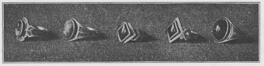
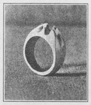
FIGURE 49. Finger rings produced by piercing, chasing and carving with engraving tools produce ruggedness of appearance
THE CARVED RING
PROBLEM 20, fig. 49. When the design is to be carried out by carving as in this problem, the blank ring must first be made and filed into shape as desired. The design is sketched on the blank and held in the ring clamp as shown in fig. 50, page 93. A variety of engraving tools, both round and flat, are needed for the carving. The cutting is a slow process and the tools have to be handled with complete control to avoid slipping. After the cutting is carried to the desired point, small needle files of assorted shapes are used to smooth up the work. Sometimes the ring is put on an arbor and the lines are more clearly defined here and there by the use of a chasing tool. The background may be matted in the same way if desired.
Left, filed and carved; center, carved; right, file grooved
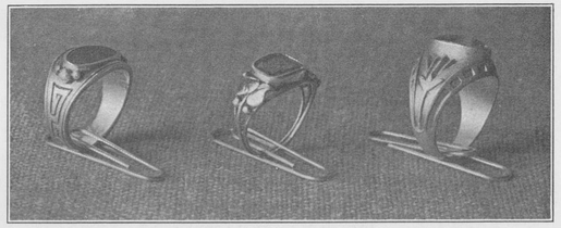
Rings in appliqué and carving
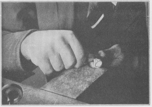
FIGURE 50. Taking out the background of the design with engraving tool, Problem 20
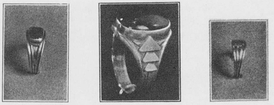
(From left to right) Belcher, Gypsy and Tiffany settings
THE BELCHER SETTING
PROBLEM 21, fig. 51. To make this setting, a ring is first made of metal thick enough to take the depth of the stone to be used. (fig. 52A) After filing the blank into shape, use the center punch to start a hole for the drill. This hole should be on the top of the ring and in the center. The size of the drill used is determined by the size of the stone. The hole should be smaller than the diameter of the stone. A small round file is used to file the metal away in making the prongs. The six prongs or points in this setting require careful filing to have each one equal in size as well as to have the openings uniform. When most of the filing has been done, a burr which is similar to a drill (fig. 52D) is used to make a seat for the stone. These burrs are made in various sizes (page 95, fig. 53) so that one may be selected having the right diameter for the stone. After the seat has been made, the file is again used to remove more of the metal and to shape the ring as desired (fig. 52A) While the ring is held in the ring clamp the stone is placed in position (fig. 54) to see if. it fits. If it does not fit exactly so that the edge of the stone bears evenly all around the seat, a little of the metal may be removed with the graver where necessary (fig. 55) The stone is again put in position and when it rests so that it is level (fig. 56) it is ready to set. During the fitting process the stone is held with a small piece of wax. The setting tool is now taken and held as shown in fig. 57 and each of the prongs is pushed gradually over the stone. After pushing the first prong in place, the one opposite should be pushed next and so on with each of the other prongs. When the prongs have been forced part way over the stone, the file is used to remove a little of the metal at the top of the prong so as to make it easier to force the point of the prong completely over. Holding the setting tool in a more perpendicular postion (fig. 58), the points are pushed over until the stone is held firmly in place. The file (fig. 59) is again used to shape the top of the prongs and then the flat graver (fig. 60) is used to cut the point as shown on page 94, fig. 52C. This is called bright cutting and completes the setting.
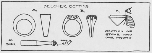
FIGURE 52. The making of the belcher setting, Problem 21
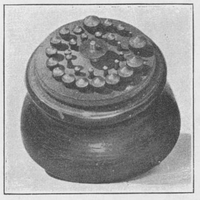
FIGURE 53. Assortment of Jewelers’ burrs used in making seat for the stone.
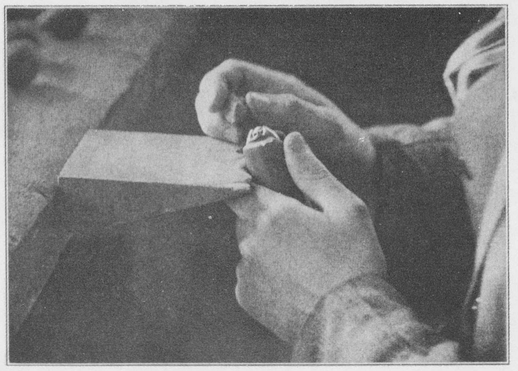
FIGURE 54. Trying faceted stone in a belcher setting for a good fit
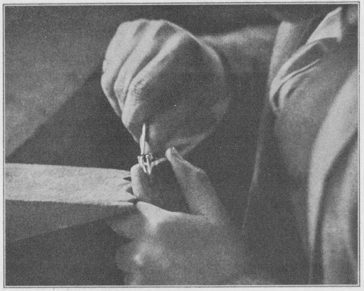
FIGURE 55. Cutting seat for stone with graver
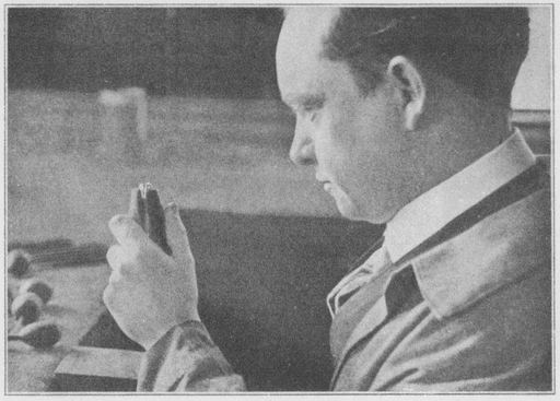
FIGURE 56. Examining the stone to prove level position
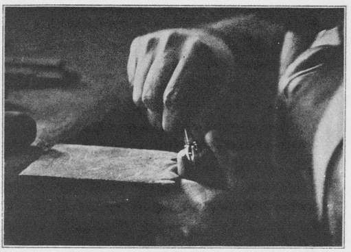
FIGURE 57. Position of the setting tool against the prong while setting stone
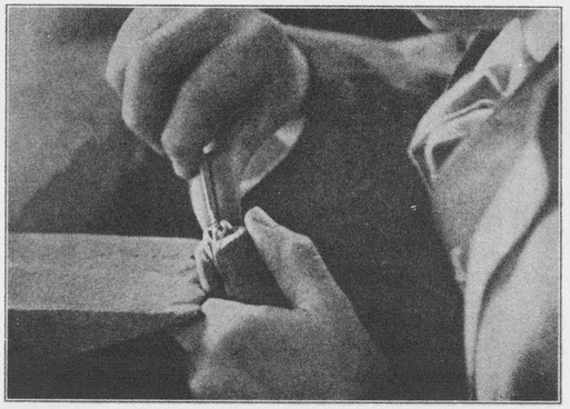
FIGURE 58. With setting tool in a more perpendicular position, the stone is made secure
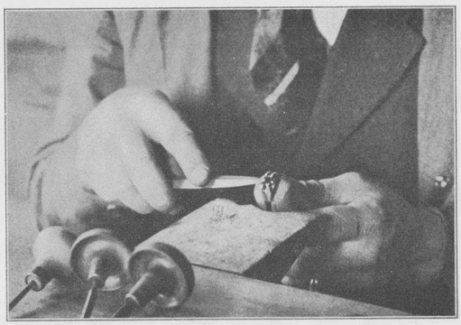
FIGURE 59. Shaping the top of the prong with flat file
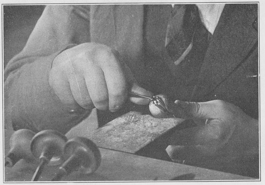
FIGURE 60. Bright cutting the prongs with flat graver
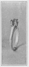
FIGURE 61 Tiffany ring
THE TIFFANY SETTING
PROBLEM 22, fig. 61. The Tiffany or prong setting is used mostly for setting diamonds or other transparent stones. A conical tube is first made of No. 18 gauge metal (fig 62A) The height and diameter of this tube is determined by the height and diameter of the stone. The shank of the ring is made and the tube soldered in place (fig 62) The file is used to make the prongs (fig 62B and fig 62D) The ring is imbedded in the shellac with only the setting exposed. Then with the engraving tool the bearing or shoulder for the stone to rest on is cut (fig 62E) The prongs are all adjusted with a pair of pliers so that the stone will fit tight. The stone is pressed down firmly until the edge rests evenly on the bearing of each prong. This leaves the ends of the prongs projecting above the edge of the stone. The next step is to push all these ends firmly over the edge of the stone (fig 62E) When the prongs are all in their places they are trimmed to a point with the engraving tool. This is usually done by making a cut on either side of the point and one on the top, and is termed bright cutting the prongs.
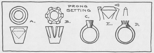
FIGURE 62. Tiffany or prong setting made in four simple steps, Problem 22
THE GYPSY SETTING
PROBLEM 23. The Gypsy ring (fig. 63) is made by taking a piece of heavy metal long enough to make the required size and as thick as the stone to be used is deep. Lay out on the blank (page 101, fig. 64A) the long and short diameter and scratch lightly on the metal. Then with the saw and file shape the blank as shown at fig. 64B. After this is carefully shaped so that it is symmetrical, it is placed over the lead block (fig. 64C) and with the ring arbor it is turned up and the ends brought together for soldering. A generous piece of solder is wedged in between the ends (fig. 64D) and if carefully fitted when soldered, the ends will spring together and show very little of the solder. After the joint is soldered, the half-round file is used to remove surplus solder on the inside of the ring (fig. 64E) It is then placed over the arbor and while it is held over the lead block it is shaped up with either a lead or a rawhide mallet. Now take the file and true up the edges on the outside, being careful to retain the lines that were scratched on the blank at the beginning. After it is filed so that it is symmetrical on either side of the long and short diameter of the block, it is placed over the arbor and a small depression is made at the intersection of these two lines using the center punch. This depression is a beginning for the drill which is used to make the hole at the top of the ring. The ring is held in a clamp during the drilling or it may be held in a vise and done with a hand drill. The size of the drill should be determined by the size of the stone, and should be much smaller than the greatest diameter of the stone (fig. 64H) After this hole has been made the next step is to take a burr (fig. 64G), and ream out the hole to the size of the stone. If the burr is allowed to sink a little below the surface of the top, it will form a seat or shoulder on which the stone rests (fig. 64F). Up to this time the ring has been flat with square corners, but it is now time to file it into the desired shape by rounding the corners and removing some of the metal at the top next to the setting (fig. 641). After the ring has been filed into shape and the file marks removed by using fine emery paper, it is ready for the stone.
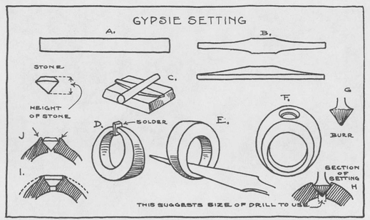
Figure 64. From ring blank to making ready for circular stone in a gypsy setting, Problem 23
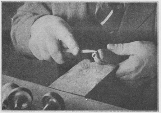
FIGURE 65. Reducing the metal around stone for streamline effect
In setting the stone the ring is held in the ring clamp (fig. 65). At first, make sure that there is a level shoulder or seat for the stone to rest on. The metal may be removed as needed with the engraving tool, and when everything is ready the stone is dropped into place. The pusher as described in Chapter 4, page 32, is used to force the metal over to the stone (page 101, Figure 64I). This is done at first at four points and then, after more of the metal has been removed with the file, the pusher is used again, and these operations are repeated until the metal has been completely pushed over and the stone held firmly in place. A little more filing is necessary to finish the setting and after using the graver to finish the edge next to the stone, the setting is completed. It is then polished and finished as desired.
Fig. 66 is worked much the same as Problem 23 except that the stone is cut to conform with the outline of the ring. In this ring the stone is oval in shape which requires a little different handling than with the circular one. A hole is drilled the required size as before and then it is necessary to file the opening to fit the stone. The shoulder or seat must be cut entirely with the graver in this case, and as the stone is cut on the arc of a circle it makes the setting more difficult. The stone is set in the same way as in problem 23.
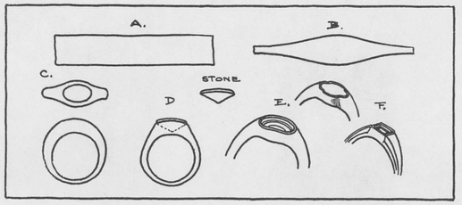
FIGURE 66. Making the gypsy setting for an oval and square stone
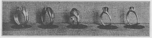
Rings in silver, in harmony with quality of stone, character of design and type of setting
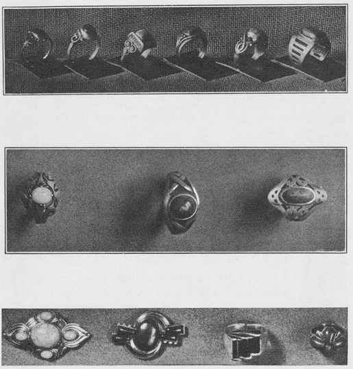
Silver rings ranging from the simple to the intricate designs, and from the single stone to the cluster