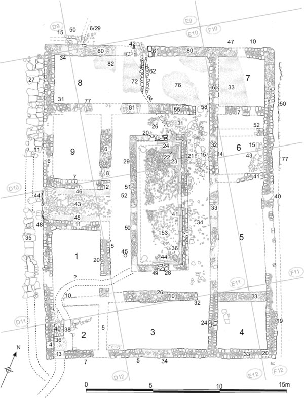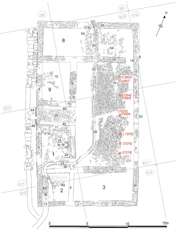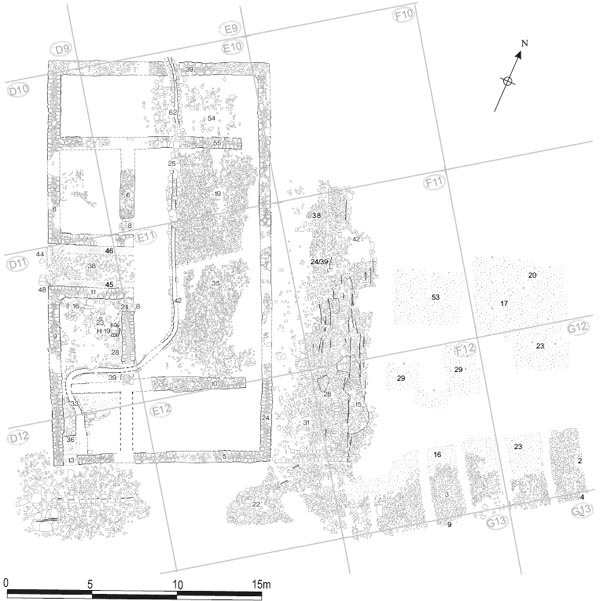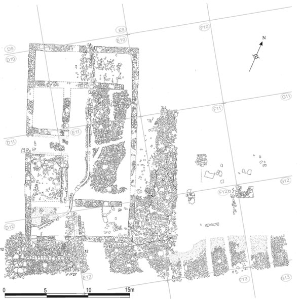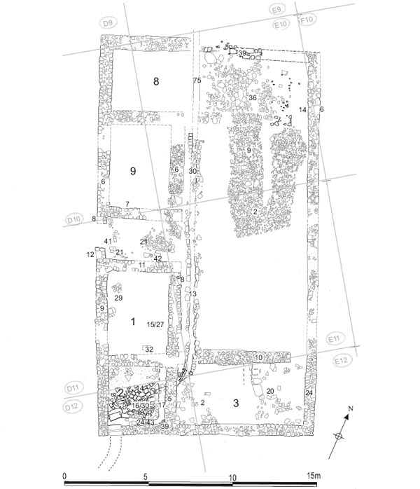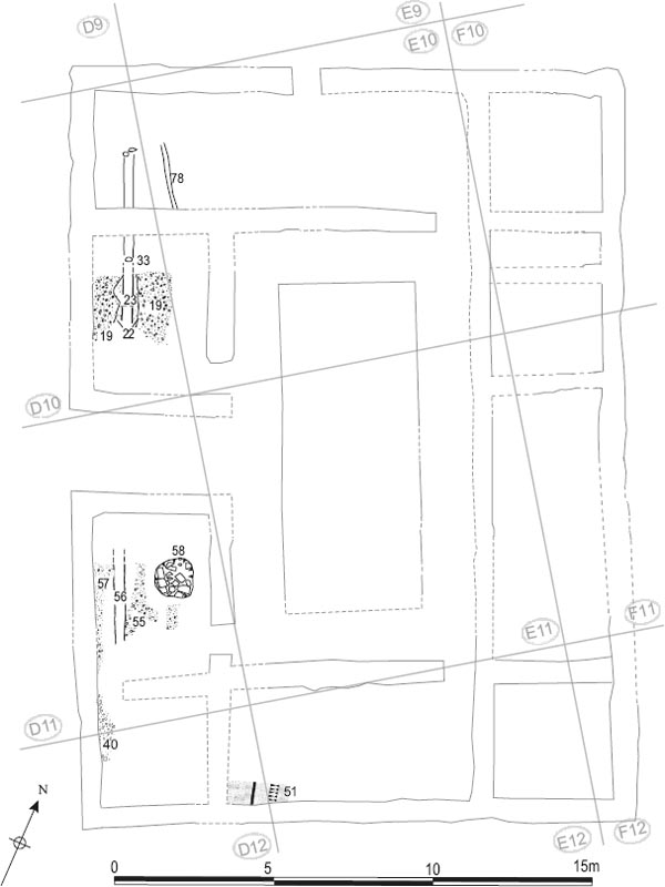
Figure 5.01: Evidence for the timber hospital (Building 21) (at 1:150) with the outline of Building 8 shown for reference.
Grid squares: D10, D11, D12, E10, E11, E12, F10, F11, F12, G11, G12
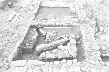
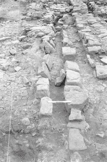
Evidence for a timber structure, which was interpreted as the primary Hadrianic phase of the hospital (valetudinarium), was identified by Tyne and Wear Museums in 1997 beneath the remains of its stone successor, Daniels’ Building 8. The remains of the timber structure (assigned the label Building XXI – here designated Building 21) were fragmentary, but it is clear that it was significantly smaller than the subsequent stone hospital (Building 8) and was not built to the same plan. Traces of the west wall of this structure had actually been recognised in 1977 in the form of strips of pink clay (D10:23, 33, D11:56; TWM 5626) which were revealed in three rooms of the west wing of the stone hospital. These actually represented lengths of the construction trench for the timber wall, shown in 1997–8 to be of post-in-trench construction with post settings interspersed along a flat-bottomed, vertical-sided trench. However the trench was interpreted by Daniels as the remains of a water channel, which he thought was associated with the stone hospital. A full account of the primary timber hospital, as revealed in 1997–8, is included in the publication of Tyne and Wear Museums’ programme of excavations (Hodgson 2003, 124–9). The following description is restricted to those features uncovered in 1977, outlining how they relate to the remains found in the more recent excavations and discussing their place in Daniels’ interpretation of the hospital’s development.
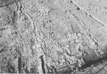
The southernmost length of the construction slot found in 1977 was encountered in the western part of Room 1, immediately to the south of the entrance passageway of the stone hospital building. A 2.50m length of the slot was uncovered here (D11:56), 0.25m wide and 0.30m deep, filled with pink clay with a slight amount of gravely silt in the bottom and some stone in the lower packing (Section 54). On the other side of the entrance passageway, the trench was seen extending northwards from the centre of Room 9, where it again appeared as a strip of pink clay (D10:23, D10:33). Three stones observed here, and thought to represent fragments of drain side walling when excavated in 1977, may have been packing stones for a couple of the posts set in the trench. (The slot had been removed by a mid-nineteenthcentury stone-lined cesspit (D10:02) in the southern part of the room.) In 1983 the pink strip was shown to extend further north (Fig. 5.02), continuing into Room 8, and was recorded as a slot 0.085m deep and 0.21m wide (D10:33). Re-excavation in 1997 revealed that the trench turned sharply westwards in Room 8. This represented the north-west corner of the timber building. Removal of the lowest metalled surface in the entrance passage exposed a further section of the trench not seen in 1977.
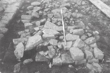
The construction slot appeared to either cut or be respected by cobbled surfaces revealed within Rooms 1 and 9 of the stone hospital. These surfaces were attributed to Building Phase 1 by Daniels, but their relationship to the construction slot suggests they must be associated with Building 21. In Room 9 the pink clay-filled slot was overlain by a wider strip of grey, clayey loam and smallish cobbles (D10:22) which apparently cut a surface composed of small, wellpacked stones (D10:19) and might be associated with the dismantling of the timber building. The presence of the compacted stone layer on either side of the slot suggests that the layer was deposited to provide a solid structural base for the timber hospital, rather than forming an internal floor level, in which case it should only have been encountered to the east of the slot. In the southern room a surface of small cobbles and sandstone chippings (D11:55) was exposed on the east side of the slot, which it apparently respected (Fig. 5.03). To the west, alongside the outer wall of the later stone hospital, the underlying bedding of orange gravel and grit (D11:57, perhaps equivalent to TWM 5634) was apparent, though here too the odd patch of cobbling was recorded. These layers were covered by clayey, grey loam (D11:53), perhaps associated with the end of the timber hospital. In the centre of Room 1 the cobbled surface was cut by a large pit (D11:58), c. 1.10m in diameter, backfilled by large stones, some of them apparently dressed facing blocks, but no finds. The stone fill was covered by and intermixed with clayey loam (D11:54), like that which extended over the slot and the gravelled and cobbled surfaces in the remainder of the room. The function of the pit was unclear.
Figure 5.01: Evidence for the timber hospital (Building 21) (at 1:150) with the outline of Building 8 shown for reference.
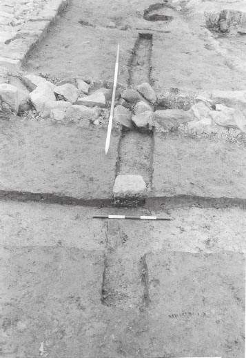
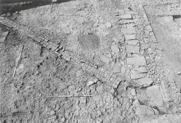
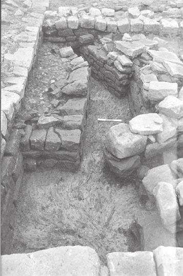
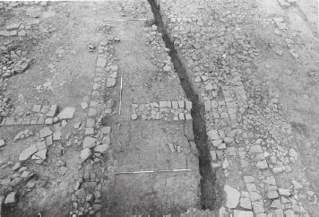
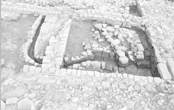
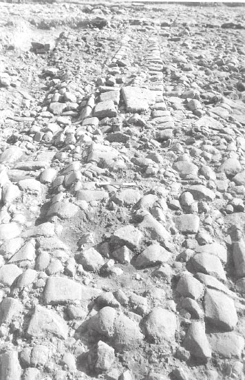
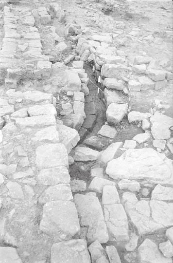
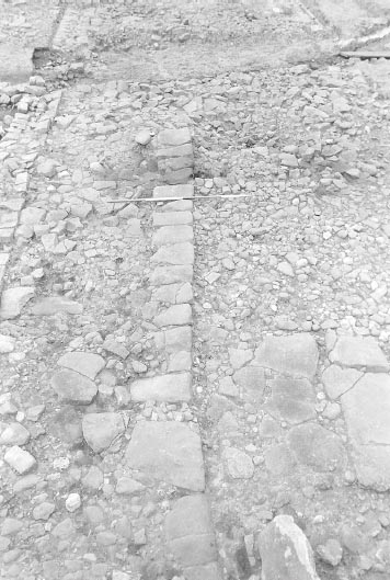
Figure 5.02: The construction trench for the west wall of timber building 21 (D10:33), from the south. The slot is cut by the internal wall foundations D10:31 of Building 8, Phase 1.
To the south of Building 21, a well-packed, worn surface of small cobbles (D12:40) revealed in Room 2 of the stone hospital, immediately to the west of the latrine drain (D12:38), may have formed part of the intervallum road surface contemporary with the timber building (probably equivalent to TWM context 5533). It thus might correspond to cobbling D11:57 and D10 19, laid on the west side of the slot further north. Daniels on the other hand considered D12:40 was a later internal floor surface, assigning it to Building 8 Phase 2 (TWM Period 3). The surface was actually level with the bottom of the west wall of the hospital (Fig. 5.03 and cf. Fig. 5.16 below), so it seems unlikely that it was laid as late as Daniels supposed. However the resilient road cobbling may have remained in use as part of the internal floor of Room 2 during Phases 1 and even 2 of that building (no other surface which could be confidently attributed to either Phase 1 or 2 was recognised in the area to the west of drain D12:38).
Immediately to the east of D10:33, another linear slot (E10:78), only c. 0.15m wide, was cut into the subsoil and filled with dark ash. It was traced over a length of 2.0m within Room 8 of Building 8, running north-south, but followed a significantly different alignment to D10:33 and the other components of Building 21 identified in 1997–8. For this reason it is not certain that this slot was associated with Building 21 or, for that matter, its stone successor, Building 8, which followed the same essential alignment. It might even predate the construction of the fort. Another feature which may predate the timber hospital is the narrow gulley (E12:50), 0.12m wide, which was exposed, cut into the natural, in a small area in the south-west corner of Building 8, Room 3.
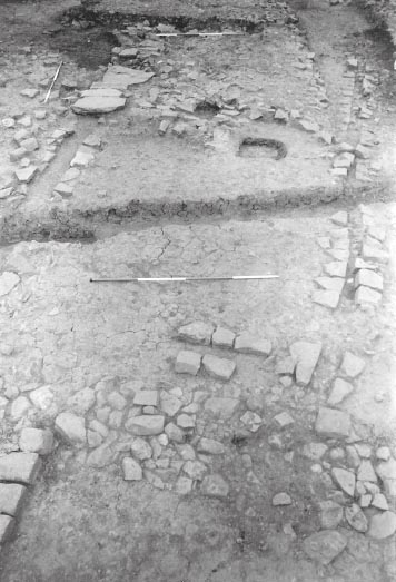
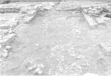
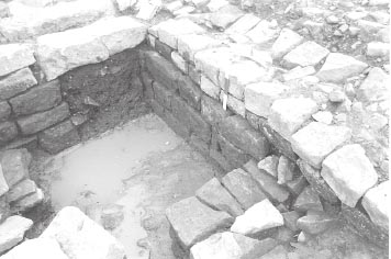
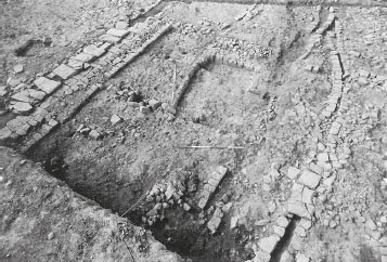
Figure 5.03: Gravel surfaces D11:55, 57 visible beneath the later floor of Building 8, Room 1 (to left), viewed from the west.
Discussion: Daniels interpreted the post-in-trench slot found in Rooms 8, 9 and 1 as the remnants of a water channel leading to the latrine pit associated with the initial phase of the stone hospital building. No other means of flushing the latrine pit was apparent in the stone hospital’s first phase and the slot certainly lined up with the stone lined channel (D12:38) in Room 2, which fed into the north side of the cesspit in the south-west corner of the stone hospital, although it was nowhere near as wide as the stone channel. It was also thought to be linked to the stone-lined conduit (E08:60, E09:06/29), to the north of the building. This connecting stretch (D10:33/E10:79) is shown on the interpretive overlay to site plan P386, but no feature is marked on the underlying plan and the plan would therefore appear to be recording interpretation rather than actual observation. It was assumed that the conduit’s side walls must have been robbed out subsequently and the channel backfilled with pink clay (the wider strip of clay in Room 9 – D10:22 – was thought to represent the robbing of the channel side-walls). Re-excavation in 1997–8 established the actual function of the trench as a construction slot for a timber-built wall. This was clearly cut later on by the stone wall foundations of Building 8, for example those separating Rooms 8 and 9 (D10:31, E10:77; cf. Fig. 5.02). No evidence was found of a conduit through these foundations or any other of the later stone hospital walls which interrupted the slot’s course. The means by which the latrine pit in Building 8 was actually sluiced out, which probably involved a combination of rainfall collected from the courtyard roof and water channelled from Cistern 1 via the courtyard, is outlined below. The possible function of the stone conduit E08:60 is also discussed below in relation to the gutters and other drains associated with the Phase 1 stone building.
The only pottery was a single, very small sherd from a flagon (D10:22).
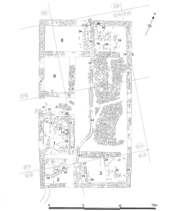
The timber structure was replaced by a stone courtyard building positioned right beside the main carriageway of the via quintana, its southern face lying between 8.8m and 9.6m further south than the south portico of the granary and the other principal buildings of the latera praetorii. The building measured 17.25m east-west by 23.70m north-south and comprised a series of nine rooms arranged around the colonnaded courtyard, with the entrance passage on the west side opening onto the intervallum street. The area to the east of Building 8 and south of the granary seems to have been open and devoid of buildings at this stage (with the exception of the small Building AV attached to the south-west corner of the granary).
The hospital’s southerly position enabled a large stone-walled cistern (Cistern 1) to be located in the open area to the north of Building 8, which the excavators labelled the ‘assembly area’, beside the western end of the via praetoria. The cistern evidently supplied water to flush the latrine in the south-west corner room of the hospital (Room 2), although the means by which this was achieved in Phase 1 was not altogether clear. However, the cistern was itself perhaps a secondary feature in the fort, like Building 8, since its layout was not parallel to the main axis of the fort, as might have been expected in the case of a primary structure. If so the existence of the cistern cannot be used to explain the position of Building 8’s predecessor, Building 21, which was laid out on essentially the same plot (though it did not cover as large an area, or, in all probability, extend quite as far south as Building 8). It has been plausibly suggested that some other building may have occupied the plot to the north, between Building 21 and the via principalis during the fort’s primary, Hadrianic period of occupation (Hodgson 2003, 126).
The four outer walls of the building were constructed with a clay-bonded core of small rubble faced on both sides by neatly-dressed stones and set on foundations of cobbles packed with pink clay. Up to three courses survived. The recorded width of the upper courses was 0.63–0.65m. The lowest course visible along the northern part of the west wall had an external offset of 0.10–0.15m giving a maximum width of c. 0.80m. A narrower offset was also visible at points along the external face of the east wall. The walls were best preserved along the west (D10:06, D11:09, D12:04) and south (D12:07, E12:05, 33, F12:20; foundations: E12:34) sides of the building. The east wall (F10:05, F11:40, F12:19), by contrast, had been demolished at the end of phase 1 and incorporated in later road surfaces with the result that the surviving masonry exhibited heavy wear and rutting, with some stones knocked out of alignment, all probably a reflection of the wear and tear caused by the carts entering the fort through the porta quintana sinistra and swinging northwards around the south-east corner of the building to reach the granary. In places only a single course remained, however at best, particularly along its northern half, it survived to a height of two courses featuring a narrow, external offset at certain points. The north wall was the most severely damaged with only two short sections of masonry surviving (E10:61, F10:10), each no more than a single course high. One of these sections, in the central part of the wall, did, however, reveal evidence of a doorway, 1.1m wide, with a pivot stone on the west side (E10:42). Elsewhere merely the foundations remained (D10:34, E10:70, 80, F10:47).
An external gutter was recorded running along the north and east sides of the building. Near the northwest corner a very short length (0.85m) of the northern gutter survived (D09:15, E09:50), immediately west of the point where the water conduit (E08:60, E09:06/29) leading from the cistern entered the building. The gutter was perpendicular to the water conduit and similar in form, comprising a pair of single faced walls, neither more than a single course high, and 0.15m apart. However the conduit walls appeared to cut through the line of the gutter, interrupting latter’s channel suggesting that construction of the conduit occurred later than that of the gutter. The east gutter (F10:50, F11:77) was constructed with a single line of blocks, a few of which were fairly well-cut, distinctive examples, oblong in form. The other side of the gutter was provided by the external face of the hospital east wall, giving a width varying between 0.20–0.40m. The gutter was traced for a total of 14.20m beside the northern half of the wall during the 1983 season of excavation and evidently extended along the full length of the building. Although the southern stretch was not exposed in 1977, it was uncovered in 1997–8 (TWM 5504; Hodgson 2003, 133, fig. 93). Alongside the south wall, a strip of sandstone fragments uncovered in 1997–8 may mark the position of another gutter associated with this phase (TWM 7984; Hodgson 2003, 158, fig. 110, cf. 133, fig. 93). The exposed stretch was 0.40m wide and extended over a distance of 5.20m eastwards from the latrine outflow drain. There was no trace of any stone blocks lining the gutter, but these had probably been robbed out at when the gutter was infilled.
Figure 5.06: The west range and intervallum drain. The section exposed by a modern pipe trench shows the flags of drain side wall D10:11 butting neatly up against the offset course of the west wall (1977).
On the west side of the building a line of flags (D10:11), c.0.70m wide, abutted the offset course of the northern half of the west wall and formed part of the intervallum surface. The cover slabs of the intervallum road drain (D10:27) rested on top of these flags, which served as the uppermost course of the east wall of the drain (Figs 5.06–5.07). This substantial drain was traced from the southern edge of the via principalis (and may have originated in the north-west praetentura where a comparable drain was recorded running on the same line alongside the western ends of Buildings 4, 5 and 6). It continued along the full length of the hospital where it linked into the latrine outflow sewer next to the south-west corner of the building. The report on the 1997–8 excavations suggested that this intervallum drain was contemporary with Phase 2 of the stone hospital rather than Phase 1 (Hodgson 2003, 160: Fort Period 3). The section through the intervallum road recorded in the course of that programme (op. cit. 169, fig. 119: Section 13) appears to indicate that the drain was cut through the Phase 1 (Fort Period 2) levels. However, the exceptionally neat manner in which the flags were laid right up against the west wall’s offset course, to the north of the entranceway, implies that the offset course was still clearly exposed when the drain was first constructed and would appear more in keeping with the high standard of construction displayed during the primary phase of Building 8 than later. There are other possible explanations for TWM Section 13 which could be compatible with an earlier date for the drain. Perhaps the drain was a secondary addition to the Phase 1/Period 2 layout, but was still built during the timespan of Period 2 and Building 8 Phase 1. Alternatively, it may originally have been constructed at the same time as the Phase 1 stone hospital, but later rebuilt along the southern part of its course (south of the hospital entrance), in Phase 2–3/Period 3, which could have involved raising it to the level of the Period 3 road surface.
Figure 5.07: The intervallum road and drain beside the west wall of the hospital. Note the way in which the flags belonging to the east side wall (D10:11) of the drain neatly abut the offset course of the hospital wall (1983).
The hospital was supplied with water from the large cistern situated in the open area to the north of the building, via a network of stone conduits. Two of the channels leading off the cistern may be associated with Building 8 Phase 1. The first, which took the form of a stone-walled, flag-bottomed conduit (E08:60, E09:06/29), 0.20m wide, ran from the southwest corner of the cistern across the ‘assembly area’, reaching the north wall of the hospital only 2.60m from the north-west angle of the building. It was well-preserved in this area, with both of the single-faced side walls surviving one and occasionally two courses high for most of their length, although no capstones remained in situ (Figs 5.06–5.07). This was probably the earliest of the stone conduits leading from the cistern to the hospital, as it followed the most direct course. Particularly instructive is the junction 3.00m south of the cistern, where another conduit, E09:34, branched off E08:60 (Fig. 5.08). Although the side walls on the combined section between the cistern and the junction had largely been robbed away, the flagged base of the channel did survive, showing that this stretch followed the alignment of E08:60, with E09:34 quite clearly forming a secondary offshoot. At the other end of its course, the conduit clearly cut through the line of the external gutter beside the hospital’s north wall (Fig. 5.09). Construction of the conduit must therefore have postdated that of the gutter and, by implication, perhaps the other principal structural elements of the building as well (although not necessarily by any great length of time). One facing stone belonging to the hospital wall survived at this point, and may have flanked the channel’s passage through into the building, but the wall was too poorly preserved to provide any further evidence on the arrangements here, so it is unclear, for example, whether the conduit made use of a pre-existing doorway through the wall.
The exact function of this particular conduit is unclear. Daniels assumed that it was designed to sluice out the latrine pit in the south-west corner of the hospital, believing it was connected to the cesspit by the clay-packed linear feature (D10:23/33, D11:56) which was traced in several rooms of the west range and which Daniels interpreted as a water channel. However, as noted above, the ‘channel’ was actually a construction trench associated with timber predecessor of Building 8, and, hence, the stone conduit cannot have been connected with the latrine. Instead, the conduit was presumably intended to provide a water supply into the north-western part of the hospital, but the internal arrangements in this part of the building have been too badly disturbed to preserve any trace of a water tank or other related features.
Figure 5.09: Conduit E09:6/29 intersecting gutter D09:15 near the north-west corner of the hospital.
The second channel (E09:34, E10:62), which branched off the first conduit 3.00m south of the cistern, entered the hospital through the doorway not quite midway along the north wall (Fig. 5.10). This was certainly used to flush the latrine during Building 8 Phase 2, when it continued directly across Room 8 and down the west side of the courtyard to the south-east corner of the building. However the conduit must have originated during Phase 1. A line of small stone blocks, which can be seen on Figs 5.10 and 5.11, extending across the north portico, evidently represented one side wall of this conduit in its first phase. Having passed through Room 8, the channel veered in a south-easterly direction across the portico and fed water into the courtyard gutter (which was only in use during Phase 1). Another sluice, perhaps following the line of the Phase 2 conduit via Room 1, may have connected the lowest point of the gutter in the south-west corner of the courtyard to the latrine pit in Room 2. This rather elaborate network of conduits and gutters would thus have enabled water to flow all the way from the cistern to the latrine, though it is not clear with how much force. It is possible that it developed in a piecemeal fashion during the life of the phase 1 building, rather than being constructed as an integrated system from the outset.
Figure 5.10: Successive phases of water conduit crossing the north range, from right to left: Phase 1 channel approaching the gap in the courtyard stylobate, centre: Phase 2/3 channel. Left: Phase 4 channel.
Figure 5.11: The north-east corner of this Phase 1 courtyard showing the surviving side wall of the water conduit passing through the gap in the stylobate.
Figure 5.13: The entranceway from the north, with the Phase 1 surfaces exposed and south pivot stone and threshold blocks visible.
The principal entrance into the building was via a passageway 2.40m wide and 5.00m long, surfaced with gravel and flags (D11:43). The door opened inwards and was probably double-leafed, although only the southern door pivot (D11:48) was found. The small extant pivot hole, D11:48, could scarcely have housed a shaft capable of sustaining the weight of a door large enough to close the entire entrance (Fig. 5.13). The leaves were checked by a threshold consisting of a row of seven neatly-cut blocks set on edge (D11:44 – comprising one short stone and six long, of which one had been removed by modern pipe D11:05). Inside, bands of unmetalled clay on the south and north sides of the passageway (D11:45–46), 0.50 and 0.35–40 m wide respectively, were tentatively interpreted as evidence for benches (visible on Fig.5.12). The fact that the gravel and flagged passage surface did not extend over these clay bands, which were simply extensions of the underlying pink clay foundation of the passage walls, was thought to reflect the presence of superimposed structures – wooden benching perhaps – which prevented this and have left no other trace. However, any such benching would also have prevented the doors in the entrance from opening fully to stand flush against the passage walls, even if the door was double-leaved, which seriously calls into question the validity of this earlier interpretation.
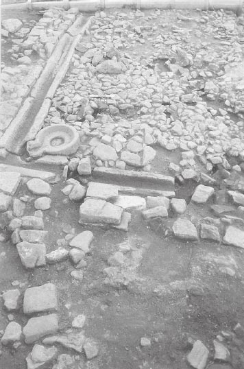
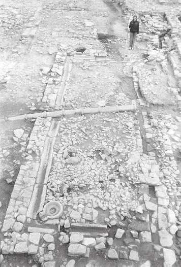
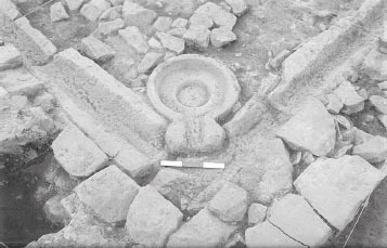
The courtyard had a stylobate, 0.45m wide, on all four sides, which presumably provided a low base for columns supporting a lean-to roof over the surrounding walkway, though no trace of the colonnaded superstructure survived. The stylobate took the form of a low wall, composed of thin, fairly neatly cut stones with little core (north: E10:20; south: E11:28, with foundation E11:49; east: E10:21, E11:18; west: E11:51). It nowhere survived to more than two courses and perhaps never originally stood any higher, as the few extant stones of the upper course which were present appeared to form a cap of interlocking flat slabs leaving scarcely any of the core exposed. The western stylobate had been largely removed by the later water conduits, but the rubble foundation remained (E10:29, E11:50). There was a neat break in the northern stylobate near its north-east corner, where the water channel, which crossed Room 8 and the north portico, was connected to the courtyard gutter, as evinced by the surviving remains of one the channel’s side walls (see above, Fig 5.11). The central part of the courtyard (which measured 9.25m by 3.00m) was surfaced by small cobbles showing hardly any wear (E10:27, E11:53). In two of the corners, the north-east and south-east (and presumably originally in all four) were circular, carved stone water basins (E10:22, E11:36), with external and internal diameters of 0.49m and 0.36m respectively. The basins were 0.06m deep, with a central area in each basin, 0.19m in diameter, recessed a further 0.035m. The basins were connected by spouts to carved stone gutters running alongside the stylobates (Fig. 5.15). The surviving 14 gutter stones from the eastern half of the courtyard were c. 0.30m wide and varied markedly in length from 0.66m–1.10m (north: E10:24; south: E11:44 east: E10:23, E11:41). The system was doubtless designed to collect rainwater running off the roof. The gutter on the west side, like the adjacent stylobate, plus the north-west and south-west basins had been entirely obliterated by the later conduit (E10:25). Around the courtyard the colonnade walkway, 1.60m wide, was surfaced with a mixture of cobbles and flags, all well-worn (north: E10:31; east: E10:21, E11:34; west: E11:52). A patch of sandy gravel (E10:26) towards the western end of the north walkway may represent part of the bedding layer for this surface. A large BB1 cooking pot (E11:45) ‘found in situ’ towards the south end of the west walkway and abutting the west stylobate foundation was probably set into the walkway surface.
The rooms of the building are numbered from 1 to 9 proceeding in anti-clockwise order from the south side of the entranceway
Immediately south of the entrance passage, Room 1 comprised an oblong chamber, measuring internally 5.00m north-south by 3.50m east-west. Its west wall was formed by the outer wall of the hospital. The north wall (D11:11), which closed the room off from the entrance passage, was 0.65m wide with no offset and survived to a height of three courses at its west end. The east wall (D11:20, E11:05), which separated the room from the courtyard, typified the construction employed in the hospital’s internal walls. The wall was 0.60–0.68m in breadth, built of roughly-dressed blocks, which varied in size from 0.13 × 0.20m to 0.16 × 0.35 m and faced a clay-bonded core of small rubble, and was set on a foundation of pink clay (E11:25). It survived two courses high with no offset. The doorway, opening onto the courtyard, was situated at the south end of this wall. A later blocking of this doorway clearly butted up against the primary north jamb (see Fig. 5.28 below). The width of this doorway was uncertain as the southern jamb was more difficult to identify than its northern counterpart due to later rebuilding and the obliteration of the masonry at the junction between Rooms 1, 2 and 3 by a modern earthenware pipe (E11:20), but was probably between 0.90–1.10m. The south wall (D11:10), which was shared with the south-west corner latrine room, displayed evidence of later rebuilding. Although this wall survived to a height of two courses and more at the west end, only the lowest course was original and was actually narrower than the course above, which must belong to a later rebuild. There was a neat break in the masonry of the lower course towards the west end the wall, indicating the presence of a doorway connecting Room 1 with the latrine (see Fig. 5.28 below). This doorway, like that in the east wall, was certainly utilised during Phase 2 of the stone hospital to enable a water conduit (D11:33) to reach the latrine cesspit and, like the other doorway, was subsequently blocked, probably when the conduit was taken out of use. Thereafter the wall was totally rebuilt. The east end of the wall had been destroyed by the modern pipe (E11:20), which made it impossible to determine conclusively the sequential relationships between this wall, with its later rebuild, and the adjoining northsouth walls, D11:20 and D12:05 (the east wall of the latrine), which themselves must have incorporated at least partially rebuilt elements.
The south-west corner of the building was occupied by a small, almost square room (2), with internal dimensions of 3.50m north-south by 3.40m east-west, which evidently served as a latrine. At the west end of the north wall (D11:10) a 0.75m wide doorway gave access from Room 1. The east wall (D12:05), which formed the other internal wall, was c. 0.65m wide with no offset. A primary wall probably occupied the same position, but was subsequently demolished to permit the passage through of the water conduit during Phase 3 of the building. The extant wall reflects the reinstatement of the wall as part of the Phase 4 remodelling of the latrine. As a result, none of the surviving stonework can be attributed to Phase 1 with certainty, though short sections of the lowest course might conceivably be primary.
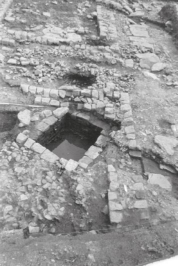
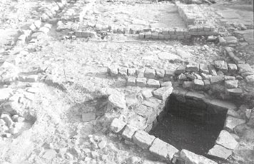
A stone-lined cesspit (D12:36), measuring 1.50 east-west by 1.30m north-south, was located in the south-west corner of the room (Figs 5.16, 5.17). This was probably the very first part of the building to be constructed. The sides of the latrine were built of large blocks up to 0.45m long and 0.20m high, this stonework being noticeably more substantial than the south and west walls of the hospital, which were set on the corresponding walls of the latrine with a careful offset c. 0.10m wide. The east side was largely removed by subsequent reconstruction, but a few of the original facing blocks were recognised beneath the later water channels. A stone-lined drain (D12:38) fed into it from the north. The drain was 0.60m wide and 0.50m deep and stood three-four courses high. To the west of the drain, a well-packed, worn surface of small cobbles (D12:40) may have formed part of the earlier intervallum road surface reused as part of the internal floor surface in Room 2 during this phase. No trace of the cobbling was recognised on the east side of the drain, where a patch of flags overlying a mixed clay layer (D12:45) might have been primary, but could also have belonged to the building’s second phase. The outlet, which was 0.65m wide and rose the full height of the cesspit walls, lay on the south side. Two 0.80–0.85m long rectangular slabs (D12:13) formed the lintel over the outlet. The base of the pit was formed by the natural clay partially covered by a deposit of light grey silt between the water channel inlet and sewer outlet. Overlying this silt was the main fill of the pit, a very dirty, tacky, dark-brown clayey soil (D12:34), which was exceedingly moist. Assuming the cesspit was cleaned out periodically, the bulk of this fill will have built up late in the life of the latrine, or even upon its disuse, but the lowest part of the fill might have been deposited at a much earlier stage, depending on how thorough the cleaning was. The course of the outlet channel beneath the via quintana was not exposed in 1977, but was revealed in 1997–8 (see Hodgson 2003, 130, 158–61, fig 90) and was shown to be of one build with the cesspit south and west walls.
The arrangements whereby the latrine cesspit was sluiced out were clear during the later phases of Building 8, when it was flushed with water from the large cistern (Cistern 1) beside the via principalis, c. 12m to the north of the hospital, but were somewhat more obscure during Phase 1. As described above, rainfall was certainly collected from the courtyard roof into a system of shallow basins and guttering around the edge of the central cobbled area. This source was apparently supplemented by water from Cistern 1, which was channelled through a stone conduit across the north range and portico to feed into the courtyard gutter near the latter’s north-east corner. The gutter in turn conducted all the water to the south-west corner of the courtyard, its lowest point. From there the water may have been channelled to the latrine pit through the southern part of Room 1, following the same route that was employed in Phase 2. This entered the Room 1 through a doorway in the south-east corner, ran westwards to the southwest corner of the room where it curved sharply round and entered the latrine chamber through another doorway. However the early arrangements in the south-west corner of the courtyard have been obscured by later alterations. Finally, it is also possible that the pit was sluiced out manually on a regular basis (Hodgson 2003, 129).
To the east of the latrine, the central room of the south wing, Room 3, took the form of a long, roughly rectangular room measuring internally 7.50m eastwest by 3.70m north-south. The south wall (D12:07, E12:05, 33) was formed by the outer wall of the building whilst the west wall (D12:05) was shared with the latrine room. The north wall (E11:10, E12:32) was 0.65m wide and was set on cobble foundations packed with pink clay (E11:26). It survived to a height of one or two courses. A doorway into the courtyard was located in the north-east corner of the room and was 1.00m wide. The east wall (E12:24) was shared with Room 4 and formed the west wall of the east wing (see below). It is clear from the way this wall was bonded with the south wall of the hospital that it was at least partially rebuilt in Phase 2. Primary flooring was only recognised in the south-west corner of the room where a small spit was cut down to the natural, a mottled pink and yellow clay (E12:51). Cut into the natural clay was a narrow gulley (E12:50), 0.12m wide, which may predate the fort. These features were covered by a dump of grey, silty clay (E12:49), varying in depth between 0.05–0.31m, which may represent levelling-up for the primary floor. This was in turn overlain by a further, undescribed layer of ‘material’ (E12:46), which may conceivably represent an occupation deposit associated with the primary phase or alternatively makeup for the flagged floor of Phase 2 (E12:47).
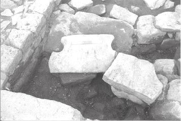
Figure 5.17: The latrine cess pit from the north-east showing the outlet opening, the larger masonry of the pit side walls and offset for the hospital walls.
The south-east corner of the building was occupied by a small room, roughly 3.70m square, labelled Room 4. The north wall separating 4 and 5 had been demolished and robbed out at the end of stone phase 1, but the 0.70m wide foundation (F12:33) survived, cut into underlying, natural, grey clay (F12:34). Its construction incorporated large stones up to 0.30m × 0.30m in size, set in greyish clay, similar to the east-wall foundation of Room 9. The primary floor surface had gone apart from three flags in the north-west part of the room, the largest being 0.35m × 0.30m.
The wall between Rooms 3 and 4 (context E12:24) continued northwards forming the west wall of the east wing, separating Rooms 5 and 6 of the wing from the courtyard (E10:14, E11:33), as well as dividing Room 7 from 8 at the north end (F10:06). The wall was
0.67–0.72m wide and utilised fairly large, faced stones up to 0.40m long, neatly laid though not well cut, set on a 0.75m wide foundation of large cobbles packed with pink clay (E10:32). It survived best at the south end and towards the north end. The central stretch on the west side of Room 5 was severely robbed.
The east wing survived very poorly as a result of its demolition at the end of Phase 1 and the laying of road surfaces over it. Room 5 runs most of the length of the courtyard’s east side with internal dimensions of c. 8.50 × 3.50m. No clear extent of flooring was identified in this room, however, nor any trace of a doorway from the courtyard as a result of the fragmentary state of the west wall. Room 6 was smaller, measuring internally 4.40m north-south by 3.30m east-west. A floor of stone flags (F10:15, F11:43) survived in the south-east corner along with the adjacent length of the 0.60m wide party wall which separated 5 and 6 (F11:41). A narrow passageway, no more than 1.00m in width, may have been inserted in the north end of this room, providing access from the east side of the building through to the courtyard. The south side of the passageway was defined by wall F10:52, only a short length of which survived, abutting the main east wall of the building (see Fig. 5.18), all archaeological deposits and structures in the western half of the room having been severely truncated down to the natural (F10:17). If wall F10:52 continued as far as the west wall of Room 6 (E11:14), it must have abutted that wall for there is no indication it was properly bonded to E11:14, nor were there any obvious remains of a doorway or threshold at either end of the supposed passageway, although only a single masonry course survived at any point. Alternatively wall F10:52 might have supported a staircase leading to an upper storey, in which case the wall may not have extended as far as the west wall and there is no need to restore doorways at either end.
Another small room (7), roughly 3.50m square internally, similar to Room 4, occupied the north-east corner of Building 8, separated from Room 6 to the south by wall F10:07. The latter wall was 0.65–0.70m wide and butted up against the external east wall of the hospital (F10:05). The west end of F10:07 did not survive, but it was clearly not bonded to the west wall of the east wing (E10:14) implying that there was either a 0.50 wide doorway between rooms 6 and 7 at this point or, more probably, that F10:07 simply abutted E10:14. A primary floor (F10:46), composed of dark-brown clay with occasional small stones, was subsequently replaced by a further clay surface (F10:33) uncovered in the western half of the room. The relationship between F10:33 and F10:46, which both occupy the same area, is not stated in the context records, but the F10:33 was recognised at a significantly higher level (0.17m) than F10:46 and hence is likely to represent a replacement of F10:46 rather than simply a duplicated context identification.
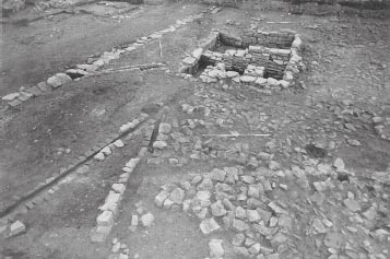
Figure 5.18: The north-east corner of the Phase 1 hospital showing the possible entrance through the east wing. Some of the later road surfaces remain.
Room 8, covering the remainder of the north wing, comprised a long rectangular room, 11.85m east-west by 3.65m north-south, making it the largest in the building. An exterior doorway was located roughly midway along the north wall with a surviving pivot stone positioned beside the west jamb (E10:42). The doorway from the internal courtyard was situated in the south-east corner of the room. It was 1.00m wide with a threshold composed of large flags (E10:58). Immediately to the west was the sole surviving stretch of masonry, only 1.70m in length and 0.65m broad, belonging to the south wall of the room (E10:55). Otherwise only the foundations (D10:31, E10:77, 81) of this wall remained. The primary floor deposits still extant across much of Room 8, especially its eastern half, was comprised of clay with odd patches of ash (E10:76). A floor of sparse gravel set in yellow-brown clay (E10:72), which might also conceivably belong to this phase, was noted in the central part of the room and may be equivalent to the layer of stone chippings (D10:32) set in clay towards the western end of the room. The gravel lay immediately to the west of the stone-lined conduit E10:25/62, and, although their stratigraphic relationship is not expressed in the context records, E10:72 perhaps represents the surface associated with the construction of the drain during Phase 1. It overlay another layer of cleaner clay, possibly natural (E10:74). Deeper excavation, by machine, of an area further to the west in the room, did uncover the natural yellowish clay (E10:45 cf. also D10:35, E10:82). To the east of the drain, an area of flat stones (E10:69) set in a more extensive spread of yellowish-brown stony clay (E10:67), with patches of ash (E10:68), may represent the remnant of a stone floor associated with this phase, overlying the clay makeup (E10:76). However, this could also be interpreted as part of the Phase 2 flagged floor, given the difficulty, across much of Room 8, in establishing a clear sequence of floors which could be assigned with confidence to successive phases.
Room 9, immediately to the north of the entrance passage, was another oblong room measuring 5.00m north-south by 3.70m east-west. The east wall had been robbed out, but the 0.85–0.90m wide clay and cobbled foundation (E10:06) survived. At the south end of this wall a doorway, 0.95–1.00m wide with a flagged threshold (E10:08), opened onto the courtyard. The north wall (shared with Room 8) had also been reduced to little more than foundations (D10:31, E10:77). The south wall was formed by the northern wall of the main entrance passage (D11:07, E11:12) and was set on clay foundations (D10:14, E11:27). A strip of pink clay (D10:20), which lay beside this wall along the south edge of the room and probably represented the residue from the construction of the wall, sealed a group of pottery and included an additional, unsealed rim sherd (see below). Much of the floor had been removed by a mid-nineteenth-century stone-lined cesspit (D10:02) and other intrusions.
FINDS
West wall
Copper alloy: brooch (no. 36, D11:09)
‘Occupation’ material, Room 3
Flint: scraper (no. 13, E12:46)
Floor, room 6
Iron: curved object (no. 70, F10:15)
Natural soil, Room 8
Coin: Trajan, 98–103 (no. 30, E10:74)
Pottery: lamp (no. 6, E10:74)
Clay floor, Room 8
Coin: illegible first century (no. 230, E10:76)
Iron: spearhead (no. 12, E10:76)
Foundation of south wall, Room 8
Pottery: disc (no. 52, E10:77)
The foundation of the south wall of Room 8 and the wall dividing Rooms 8 and 9 both contained a few sherds of BB2, suggesting a construction date of c.160. Some of the rooms produced only a few sherds of pottery in this phase (Room 1, less than ten; Rooms 6, 7 and 9 three each), although it is likely some pottery has been lost as some contexts contain only rims, or more rims than body sherds. The largest group of pottery comes from Room 8, including two sherds of Antonine samian and a Mancetter-Hartshill mortarium rim dated 170–230, and a sherd of a Nene Valley coloured coated pinch-neck flagon of the third century.
The presence of BB2 in the pottery assemblage associated with Phase 1 of the stone hospital is consistent with a date of c. 160 for the building’s construction. The small amount of third-century Nene valley ware in the assemblage, comprising two sherds, plus a sherd of a third-century Horningsea storage jar, from context E11:18 and three sherds from a single vessel in E10:58, are more likely to represent contamination or might conceivably reflect the lifespan of the Phase 1 building which may have extended into the third century.
The latrine pit contained approximately 45 sherds of pottery, mainly of BB1 and flagon fabrics, but with a few sherds of BB2 and allied fabrics. There was also a spout from an Antonine Corbridge mortarium and a sherd of decorated samian dated 130–65 (D12:34). The backfill of the associated primary drain contained a large group of pottery consisting of BB1, local grey wares and flagons and two sherds of Hadrianic samian (D12:37). Strictly speaking these assemblages only provide termini post quem for the backfilling of the two structures when they went out of use, which in the case of the drain channel did not occur until the beginning of Phase 3, whilst the pit was largely filled when the latrine was remodelled in Phase 4, though the section nearest to the outflow drain continued to function right up to the end of the hospital’s life. However the material from the two groups appears much earlier. The pottery from the latrine channel, in particular, looks to be a second-century group. This might imply that the pottery all derived from the primary fills at the very bottom of the channel and pit, where it had escaped periodic cleaning out.
Grid squares: D12, E12, F11, F12, F13, G11, G12, G13, H11, H12
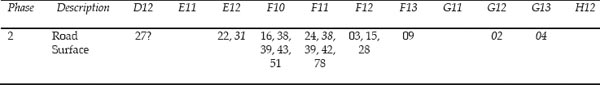
The western stretch of the via quintana, between Buildings 8 and 7 to the north and Barrack 9 to the south, preserved a good sequence of road surfaces (see Table 5.01) which helped to establish a reasonably clear phasing for the hospital and this part of the fort. In all, four successive phases of the via quintana were identified in this area during the 1975–84 excavations. Because of the eccentric southerly position of the hospital, by comparison with the other buildings of the central range, the east-west carriageway was only 5m wide between the hospital and Building 9, increasing to c. 14m–15m further east. The roadway continued westward through the single gate portal of the porta quintana sinistra (see Chapter 17).
Table 5.01: Sequence of road layers on the west via quintana and the street east of Building 8
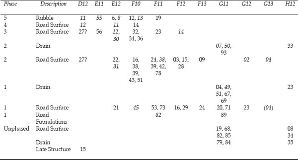
Italics = Contexts with dateable material
The lowest road surface identified during the Daniels excavations was composed of fine gravel and very small cobbles, roughly 0.05m in diameter. This was recognised in one relatively small section of the via quintana south of the hospital (E12:21), where a modern trackway (E12:45) had removed the later road levels, and, more extensively, in the area east of the hospital and south of the granary (F11:53, 73, F12:16, 29, F13:24, G11:20, 71, G12:23), where the later road surfaces were not present. A similar level was also observed to the north in the alley between the granary and the hospital (F10:45). The surface generally had an orange colouring due to iron panning and was not extensively worn. It varied in thickness to upwards of 0.10m. The gravel and small cobbling was set on a layer of larger stones (F11:82, G11:89), which was most clearly recognised in the area immediately south of the granary (grid squares F11, G11). This layer was not described in detail, but was interpreted as a foundation or makeup for the overlying gravel and cobble surface, which, in this particular area, was interspersed with flags ranging from 0.05m to 0.20m in diameter (cf. F11:73).
The gravel and small cobbling was assumed by Daniels to be the primary surface and was considered to be contemporary with the initial phase of the stone hospital. However, the excavators in 1977 and 1983 were unaware that Building 8 had been preceded by an earlier structural phase, represented by Building 21, the timber hospital. In these circumstances, it is conceivable that the underlying ‘foundation’ of larger stones (F11:82, ) actually formed an earlier road surface associated with the primary, Hadrianic, occupation in this part of the fort. Conversely, if the layer of larger stones was indeed a makeup deposit for the Period 2 (Building 8 Phase 1) via quintana metalling, an earlier road level, unrecognised by the 1975–84 excavators, must be postulated.
On the south side of the road, a stone-lined drain or gutter (F13:13, G13:05), associated with Barrack 9, was interpreted as part of the primary layout of the road, although this may in fact have been associated with the Period 2 stone barrack rather than the Period 1 timber block. The outflow channel from the latrine in the south-west corner of the hospital was not investigated in 1977, but was uncovered in 1997–8 (TWM 7171), when it was shown to have crossed the via quintana and continued southward along the intervallum road to the west of Barracks 9 and 10 (7660). The intervallum drain running down the west side of the hospital was shown to feed into the outflow channel midway across the via quintana (see Hodgson 2003, 158–60).
The Phase 1 road produced only seven sherds of pottery, including BB2 (surface F10:45, foundation F11:82).
The second phase of the stone hospital saw it transformed into a rather more utilitarian structure. The east range of rooms was demolished and cobbled over to form a north-south street corresponding to the second phase of road surface identified by Daniels on the via quintana. This street was heavily rutted and worn and had been patched. The courtyard too was radically altered with the demolition of the colonnade and the covered ambulatory around the central cobbled area. A stone-lined water conduit was taken through Room 8 across the courtyard and then through Room 1 to feed into the latrine in Room 2.
New floor surfaces were laid in at least some of the rooms. These cannot always be directly associated with the secondary water channel and in such cases their attribution to a particular phase is assumed on the basis of their relative position in the stratigraphic sequence rather than proven.
Inside Building 8, the stylobates were eliminated and the gutters and water basins were filled with a greygreen clayey loam (E10:16–18, E11:31) and, in places, rubble (E11:30). The primary courtyard surface was overlain by a mixed layer of very dark, grey-green soil and pink clay with patches of daub, variouslysized stones and charcoal (E11:32). The layer had a pinkish colour overall. This probably represents residue from the demolition of the east wing. A new, rough surface of flagging and large cobbles (E10:19, E11:35) was laid over the yard, overlying a level of light clayey silt, between 30mm and 50mm thick. A line of six postholes, running parallel to the east wall of the courtyard and cutting through the east stylobate wall, was recognised during the 1997–8 excavations (TWM 7253, 7255, 7264, 7276, 7278, 7280; three were apparent on 1977 plan P98, cf. Fig. 5.19). The relationship of these postholes to the Phase 2 or later courtyard surfaces could not be ascertained, since the latter had all been removed in 1977. However, the fact that the postholes cut through the neatly constructed stylobate wall renders an association with the initial Phase of the stone hospital highly unlikely. Conversely, the manner in which the postholes closely followed the line of the stylobate indicated the posts had most probably been erected at the beginning of phase 2, before the stylobate had been covered over by the new cobbled surface which extended across the full extent of the yard.
A major alteration was also made to the course of the water channel (E09:34, E10:62), which entered the hospital through a doorway almost midway along the north face. This originally fed water from Cistern 1 into the peristyle gutter in the north-east corner of the courtyard (see above Phase 1). The channel was now realigned to run directly to the latrine in the southwest corner of the building, diverging from the earlier course – which must have become redundant and had largely been robbed out – in Room 8 and following a north-south course across the courtyard (E10:25, E11:42), where some of its cover slabs still remained in situ (Fig. 5.20). It then turned westward to enter Room 1 through the pre-existing doorway, running along the south side of the room into the south-west corner where it turned sharply southward to pass through the doorway connecting Rooms 1 and 2 (D11:33 – see Fig. 5.21). In the north-west part of Room 2, a junction was made between the new channel and the earlier stone channel (D12:38) leading into the cesspit in the southern part of the room. The secondary conduit was significantly narrower than primary channel in Room 2, which resulted in a slightly awkward junction where the two eastern side walls met (Fig. 5.22; cf. Fig. 5.16 above). It is likely that the channel was originally covered by capstones, though none survived in Rooms 1 and 2, having probably been removed for use elsewhere when the conduit went out of use and was backfilled.
The north-south channel (E10:25, E11:42) removed any trace of the gutter and the two water basins which must have lain on the west side of the primary courtyard and reduced the west stylobate down to foundations for virtually its entire length. However the drain did not reuse the west stylobate to form one of its side walls as might have been expected. Instead the west wall of the conduit ran a mere 0.25m to the east of the west stylobate east face. The circuitous course of the southern stretch was presumably determined by the position of the two doorways into Rooms 1 and 2 which provided the easiest access to the cesspit, obviating the need to demolish walls. The drain walls survived up to four courses high in these two rooms and were constructed of long thin stones laid lengthways. A deposit of grey silt (D11:50) filled the bottom of the conduit.
A new surface of fine gravel (D11:38), 0.01m–0.03m deep, was laid in the entrance passage. This surface, like its predecessor, still respected the clay bands beside the passage walls. No stratigraphic link could be made between the yard and passageway surfaces, however.
In Room 1 the early levels, including the features associated with Building 21, were covered by a layer of grey clayey loam (D11:53), which might conceivably represent either an occupation deposit associated with the Phase 1 or makeup for the subsequent phase of flooring. This was overlain by a gravel floor (D11:39), which seems to be associated with the drain channel (D11:33) running along the south side of the room, and which had the effect of raising the floor level about 0.15m. This gravel survived only patchily and was not found at all in the north part of the room.
Figure 5.20: The intervallum drain alongside the west wall of the hospital plus three phases of water conduit entering the hospital.
A rectangular stone setting (D11:19) was placed against the east wall. It took the form of a large flat slab framed to the north, south and east by faced stones forming a wall, one stone wide, around the slab on these three sides. Two courses of the wall survived on the east side. The feature as a whole measured 0.85m north-south and 0.55m east-west and there was some blackening in the centre. To the south of the setting, a spread of charcoal and coal (D11:28) (1.15m N–S, 0.60m E–W) abutted the east wall of the room and stretched for c. 1.15m southward to a clay edge or strip which ran perpendicular to the east wall. This clay ‘edge’ followed the same alignment as the north jamb of the doorway for at least 0.90 m into the room and may conceivably have continued further originally. Its interpretation is unclear, but it perhaps represents the base of a timber partition screening off the doorway. To the north of the stone setting an area of grey loam (D11:25) was heavily flecked with coal. The framed slab presumably formed either a hearth or perhaps the base for an upright brazier. The coal and charcoal deposit may represent the residue from a fuel stock next to the hearth or perhaps the trail resulting from fuel being carried into the room.
It is unclear whether gravel D11:39 represented a surface in itself or served as bedding for a flagged floor. The gravel survived much higher in some areas – notably between the conduit and the south wall of Room 1 and in a small patch against the west wall – than others. It seems likely that the water channel at least was covered by flags, which were subsequently removed for reuse elsewhere when the drain went out of service and was backfilled. Furthermore a single flagstone remained to the north of the conduit in the east doorway with the later blocking wall sitting on top of it. There was no trace of gravel in the northern part of the room, which was covered, incompletely, by large sandstone flags (D11:16). The flagstones may represent a later, Phase 3 resurfacing, in the north part of the room, but it is equally possible that there was a combination of flags, gravel bedding and infilling from the start. Associated with flagging D11:16 was a BB2 cooking pot with latice decoration (D11:23), set into the floor, its rim having been deliberately trimmed, and probably used for some sort of storage. Seven-eighths of the vessel survived and a round stone found within the pot may have originally served as a lid. The vessel type first appears in the late second century.
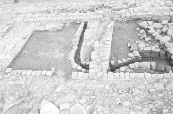
Figure 5.22: The latrine in the south-west corner of the hospital (Room 2) showing successive phases of water channel.
In the latrine, the spread of cobbles (D12:40 = TWM 5533?) to the west of the drain channel, which may originally have formed part of the primary intervallum road surface (see above), perhaps still remained in use during this phase as part of the room’s flooring. A mixed clay-loam with some charcoal flecking overlain by fragmentary stone flagging (D12:45) covered the north and north-east part of Room 2. It is not clear whether this flagging and clay makeup should be assigned to Phase 1 or 2, or whether the surface was in use during both phases.
In Room 3 no surfaces were identified which could be clearly associated with this phase. All the Roman period deposits in the central portion of room had been removed by a two nineteenth-century drain conduits (E11:07; E11:04/16) and associated disturbance (E10:07). The flagged floors recorded in the remainder of the room were more likely associated with later phases of activity, this being particularly clear in the case of the successive levels of flagging in the western part of the room.
The structural history in the area of Room 8 is more difficult to interpret, with a dearth of distinct, uniform floors and features clearly associated with successive phases. However the remains of a flagged floor (E10:54) uncovered in the centre of the room were probably associated with this phase, the flags being level with the cover slabs of the drain. The wall separating Room 8 and the courtyard was very poorly preserved and consequently there was no way of confirming whether the realigned drain passed through a pre-existing doorway here, although this is very likely. Indeed the secondary conduit lay close enough to the line of its predecessor of Phase 1 for both conduits to have shared the same doorway. A spread of small cobbles (E10:66), immediately to the east of the conduit, may have been deposited in this doorway after the stretch of the original Phase 1 conduit, leading to the north-east corner of the courtyard, had been robbed out.
In Room 9, a floor consisting of a make-up layer of yellow-white sandstone chippings (D10:10) with a surface of small flat slabs and gravel on top (D10:15) was attributed to Phase 2 by Daniels. This covered a layer of light-medium grey, clay-loam (D10:21).
INTERPRETIVE PROBLEMS – THE PHASE 1 AND PHASE 2 FLOOR LEVELS
The description of Building 8 Phase 2 provided above is largely that arrived at by Daniels following excavation in 1977 and 1983. However, the discovery, in 1997–8, that there had been a timber building (21), preceding the stone hospital, raises questions with regard to certain aspects of that phasing. Specifically, both in Room 1 and Room 9, only a layer of clay loam (D10:21, D11:53) separated the floor levels attributed to Phase 2 by Daniels from those now reinterpreted as being associated with Building 21. In neither room was a distinct intervening surface identified, which might be attributable to Phase 1. This might be explained by a truncation episode which had removed the Phase 1 floor. However, it is also possible that Daniels’ Phase 2 floor should actually be assigned to Phase 1. In Room 1, in particular, the level of the floor in relation to the surrounding walls would not preclude this. Unfortunately the quantities of pottery from these floor levels were too small to provide a conclusive guide either way.
FINDS
Floor, Room 1
Stone: lid (no. 35, D11:23) associated with buried pot
Coal/charcoal spread, Room 1
Lead: plug (no. 3, D11:28)
Secondary courtyard surface
Decorated samian: 125–45 (no. D28, E11:35), 160–80 (no. D29, E11:35)
The rooms produced little pottery in this phase. A BB2 cooking pot (D11:23), complete apart from its rim and with a circular stone lid, had been deliberately incorporated into the floor in Room 1.
BB2 and allied fabrics made up three quarters of the assemblage, and there was a sherd of East Gaulish samian dated to the late second or first half of the third century (E11:32).
The fill of the water conduit north of the building contained a sherd of Central Campanian amphora dated to after the mid-third century, and a sherd of East Yorkshire grey ware of the late third century or later (E09:33, E09:34). In the northern part of the courtyard the fill included a third-century vessel of form Gillam 151 (E10:25), whilst further south (E11:42), although there were only five sherds from the lower fill of conduit, these did include a sherd of south-east reduced ware and a scrap of Nene Valley (E11:39).
Where the channel extended into Room 1 (D11:33), BB1 made up approximately half of the pottery assemblage of the lower fill of the conduit (D11:49), while there was only a small scrap of possible BB2 in the silt layer at the very bottom of the channel (D11:50). Most of the pottery could be secondcentury in date. This stretch of the conduit may have originated in Phase 1 (Fort Period 2), which would not be contradicted by the assemblage from the lower fill and silt.
The surfaces within the Phase 2 courtyard produced a quantity of pottery, approximately half of which was made up of BB2 and allied fabrics, indicating a third-century date. Context E11:35 also had sherds from three Antonine samian vessels, a decorated bowl dated 160–80 and an East Gaulish bowl of the late second or first half of the third century. A thirdcentury date is also indicated by some sherds of Nene Valley colour-coated ware in another sizeable group filling the east gutter (E11:31).
The via quintana was resurfaced following the demolition of the hospital east range. The new metalling consisted of medium-sized cobbles, on average c. 0.10m in diameter, worn very smooth and flat, with small building rubble and a lot of quern stones set into it (context E12:22). This surface was recognised on the east-west carriageway between Buildings 8 and 9 and also running north-south over the former east wing of the hospital, on either side of the primary east wall (F10:05, F11:40, F12:19) of that building, clearly demonstrating that the second phase of the western via quintana identified by Daniels followed on from the demolition of the east range of the hospital. Towards its south end, where it was three courses high, the surviving masonry of the former east wall protruded above the surrounding road surface (E12:31, F12:28, F12:15), which lay against the lowest course of the wall. The cobbling continued into the alleyway between the granary and the hospital (F10:16, 38, 43) where the gutter alongside the hospital’s primary east wall was filled by similar material (F10:51, F11:78). The west side of this northsouth metalling, adjacent to the east wall (E10:14, E11:33, E12:24, F10:06) of the truncated hospital building, did not survive, having been removed by a trackway (E10:13, E11:17, E12:45, F11:20) of probable early modern date.
Table 5.02: Via quintana road levels contemporary with Building 8 Phase 2 (Period 3)
This Phase 2 roadway showed signs of heavy wear, with deep rutting on the surface and areas of patching on the north-south carriageway (contexts F11:38–39; see Figs 5.23–5.24; cf. Fig 6.21 below). The ruts were also particularly pronounced on the north-south carriageway and seemed to run past the south-west steps of the granary. The former east wall of the building had been demolished down to its bottom two or three courses, and these surviving remains too were heavily rutted with the stones knocked out of alignment. This rutting was probably caused by the movement of laden supply carts towards the granary and is a common characteristic of roads which have reinforced surfaces in them, like kerbs that have been incorporated into the surface, or, as in this case, where a building has been demolished and the lower courses of the walls used in the road surface. The carts probably entered via the porta quintana, continued along the via quintana and turned north at the south-east corner of the Phase 2 hospital. They were probably unloaded beside the south-west steps of the granary.
Much of the surface overlying the east wing was cleared by the excavators in 1977 and 1983 to reveal the remains of the hospital, but some areas of metalling were left in place, notably by the south-east corner (TWM 7698, corresponding to E12:22) and partially alongside and overlying the primary east wing (TWM 5501 = F12:15, F11:24/39, 42), and were re-exposed in 1997–8 (Hodgson 2003, 135–6, fig. 94).
The cobbling and patches in the roads produced BB2 and Nene Valley colour coated ware, indicating a third-century date.
This phase of activity, like those immediately preceding and following it, was defined principally by a combination of significant realignment of the channel which flushed water through the latrine, alterations to the layout of the latrine itself and the laying of new surfaces in the courtyard and entranceway. The composition of the courtyard and passageway surfaces resembled that of the third layer of metalling recorded by Daniels on the via quintana and the road east of the hospital, being largely made up of squared blocks which may have derived from the demolition of an unidentified structure. This helped to convince the excavators that all these surfaces should be treated as part of the same structural phase.
In the entrance passageway a new layer of metalling, comprising a pack of medium-sized sandstone blocks (D11:21), was laid over the preceding gravel surface. The pack survived best towards the east end of the passage. Towards the west end a rough line of faced blocks (D11:41) over the rubble and stone packing was interpreted as providing a step down from the intervallum street, though the impression provided by the surviving remains may be misleading. Later disturbance in the central part of passageway – in the form of a layer of greenish-grey, clayey-loam with a lot of pink clay (D11:36) – had removed any trace the stone pack immediately to the east of the ‘stone line’ and it is likely that D11:41 was actually simply part of the same stone pack as D11:21, which originally extended, uninterrupted, for the full length of the passageway.
The excavators considered that, as initially constructed, the layer of stone blocks of D11:21, like previous entranceway surfaces, did not encroach on the clay bands alongside the passage walls, which were interpreted as the site of side benches. At a later stage (Phase 4?) it was argued, these benches were removed and the pre-existing surface pack of cut sandstone was extended (D11:42) up to the side walls. As noted above, the theory of side benches is questionable, since they would have prevented the door leaves opening fully to rest against the passageway walls. If the stone layer alongside the passageway walls was actually distinct from that covering the central carriageway, which is by no means certain (D11:42 does incorporate some large blocks which could form an edge on the south side of the passageway but this is much less clear on the north side), it is perhaps more likely that the slabs and blocks along the side walls (D11:42) were laid first, in effect as pavements to keep pedestrians clear of any mud on the main surface. The level in the main carriageway may subsequently have been raised to the same level (D11:21).
It should be noted that stone surface D11:21 was only attributed to Phase 3 because of the relative sequence in the passageway and the characteristics of the surface itself which were considered to resemble the Phase 3 surfaces in the courtyard and on the road levels. The relationship of the stone pack to the nearby Phase 4 water conduit was, unfortunately, unclear, since the stone surface did not continue unbroken up to the channel. Hence, it was not possible to establish conclusively whether the channel was contemporary with this passageway surface or was a later insertion, as proposed here.
A new surface was laid in the courtyard, composed of medium-sized stones including squared blocks and some flags and boulders (E10:11, E11:22), all well packed and worn. Towards the south end of the courtyard, where the surface was very shattered, smaller stonework, including many tiny slabs (E11:23), was used. (Site Plan P92).
The defining feature of this phase was the re-routing of the water channel from the south-west corner of the courtyard to run southward into Room 3 and then diagonally across Room 2 to empty into the north-east angle of the cesspit. This meant the earlier, circuitous channel through Rooms 1 and 2, with the pronounced and conceivably problematic bend where it negotiated the doorway between the two rooms, could now be taken out of service and backfilled. The doorway between Rooms 1 and 2 was blocked. The blocking wall, between three and four courses of which survived, cut the uppermost courses of the drain walls, one course of blocking actually sitting in the channel, D11:33, with some fill beneath, demonstrating that this occurred whilst the conduit was being taken out of service (see Fig. 5.26). The backfill in the redundant channel overlying a 30mm thick deposit of yellow-grey drain silt (D11:50, E11:40) was similar throughout, consisting of a mixed, dark greenish-grey, clayey loam, siltier with much charcoal flecking and coal towards the bottom (D11:49, E11:39), and with a lot of pink clay and stone in the upper packing (D11:40, E11:38). Several capstones were found in the fill in Room 2 (D12:37). The doorway between the courtyard and Room 1 was also blocked and a new entrance provided at the north end of the east wall. In this case the blocking (D11:31) was simply carried over the drain fill (see Fig. 5.27), indicating that this operation was accomplished after the modifications to the water channels had been completed, though not necessarily long after. The new, 0.75m wide threshold (E11:24), in the north-east corner of the room, was composed of small, flat sandstone slabs and a flagstone with a peck hole, presumably to hold the door pivot, and now, if not earlier, the room was floored with flagging D11:16 (see above Phase 2).
Just to the north of the junction between the old and the new drain courses the channel still retained two of its cover slabs. The replacement channel (E11:43) was not more than 0.20m wide, narrowing to c. 0.15m at certain points within Room 2, with even less space between the upper courses. The side walls were built of small, neat stonework. Larger stonework was employed in the stretch approaching the cesspit, where the north-west wall (D12:23) of the channel survived up to three courses (0.40m) high and two courses of its south-eastern counterpart (D12:35) remained (cf. Fig. 5.28). The terminal of the conduit cut through the former east wall of the cesspit and projected into the pit, virtually closing off the southern end of the primary and now backfilled channel. Thus, by straightening out the course of the channel to a considerable degree, the new arrangement was presumably intended to improve the flow of water into the cesspit.
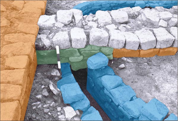
Figure 5:26: The passage of the Phase 2 (possibly Phase 1) conduit between Rooms 1 and 2. Pink represents Phase 1 walls. Blue: the stone conduit. Green: blocking of the doorway (Phase 3) with the wall later being rebuilt over the top.
Construction of the new water channel must have entailed the demolition of much if not all of the wall between Rooms 3 and 2 and it is likely that, to accommodate the new conduit, Room 2 was enlarged with its east wall shifted c. 1.80m eastward. The east face of the new, 2.50m long, east wall (E12:35) survived, the west face having been entirely removed (Fig. 5.29). A wide doorway at the north end of this wall gave access to the latrine from Room 3, whilst direct access into Room 2 from the courtyard may also have been provided where the conduit passed through wall E11:10 (Fig. 5.30). Construction of the drain passage must have entailed the demolition of wall E11:10 at this point, and the surviving remains indicate the rebuilt wall was not carried over the channel, its place presumably being taken by a doorway. The channel was doubtless covered by capstones, providing a convenient flagged threshold. To the west of the new east wall, E12:35, a floor of sandstone flags (E12:47), laid on a 0.10m–0.15m deep makeup (?) deposit of undescribed ‘material’ (E12:46), may be associated with this enlargement of Room 2. A spread of sandstone flags (D12:14) to the north-west of the new conduit may, in part at least, be the equivalent E12:47, but here it is more difficult to differentiate the successive levels of flagging associated with phases 3 and 4 than it is in the area immediately to the east.
In what remained of Room 3, now reduced to an internal length of 5.40m–5.85m, there was a flagged floor (E12:36) butting up against the east face of wall E12:35. Only a narrow area of this flagging survived, noticeably cracked with wear, right beside the wall, the remainder having been removed by nineteenthcentury conduits (E11:07; E11:04/16; E10:07), but it was once probably an angular floor surface of evenlycut squarish slabs. In the eastern part of the room a fragmentary floor surface, consisting mostly of small slabs and very shattered flags (E12:20), may belong to this phase and may indeed form the continuation of flagging E12:36, though much damaged. In addition a line of three stones (E12:29), was interpreted as possibly forming part of a north south dividing wall. This may, however, be a misleading impression created by the destruction of the deposits immediately to the west and partial dislocation of the three stones by the post-Roman conduit and disturbance (E11:04/16). The stones may in fact simply have formed part of the flagged surface E12:20.
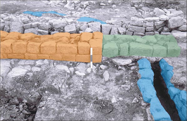
Figure 5:27: The passage of the Phase 2 conduit from the courtyard through the doorway into Room 1 (foreground). Pink: primary east wall of Room 1. Blue: the conduit. Green: the Phase 3 blocking of the doorway, after this conduit had been replaced.
No distinct floor surfaces were recognised in Rooms 8 or 9 which could be assigned to this phase.
Figure 5:29: Room 3: remains of Phase 3 wall E12:35 separating 3 (foreground) from an enlarged Room 2. The Phase 4 wall with capstone over the drain is visible in the background. Also visible beyond wall E12:35 are the fragmentary remains of flagged floor E12:04, dark clay makeup E12:03 and V-shaped drain E12:28 associated with timber building N, overlying the flagged floors of the hospital.
FINDS
Metalling in entranceway
Copper alloy: strap-end (no. 160, D11:21)
Courtyard
Pottery: counter (no. 54, E10:11)
Courtyard surface
Decorated samian: 160–200 (no. D26, E11:22), 160–90 (no. d27, E11:22)
Graffito: (no. 11, E11:22), (no. 20, E11:22)
Quern: lava (no. 22, E11:22)
Stone: throwing stone WSS113 (E11:22)
Upper fill of secondary drain
Lead: disc (no. 25, E11:38)
The pottery from Phase 3 of the building is no later in date than that found in Phase 2, apart from a single sherd of late third- or fourth-century East Yorkshire grey ware in the passageway that has perhaps been pressed in from a later layer (D11:21). The silt in the bottom of the tertiary drain in Room 2 produced only four sherds, consisting of two mid- to late Antonine samian sherds, two sherds of south-east reduced ware and a scrap of flagon.
Most of the Phase 2 conduit remained in use in this phase. The later pottery types found in the courtyard channel fills (see Phase 2) might therefore have been deposited during or at the end of Phase 3, including a third-century vessel of form gillam 151 (E10:25), plus a very small body sherd of Nene Valley (1 gm), and a body sherd of south-east reduced ware which was not much bigger (E11:39).
However the section running through Rooms 1 and 2 was taken out of use and completely backfilled at the beginning of Phase 3. The full pottery assemblage from the fills in this stretch of the channel comprised at least 40 body sherds. A higher proportion of BB2 would be expected if this was simply a third-century group. BB2 was present in the upper fill (D11:40), but the BB2 in the lower fill (D11:50) was only possibly BB2, and comprised one small sherd (out of a total of 12+ sherds). There was also a sherd of shell-gritted ware from the context, which is usually third-century Dales ware, but some second-century shell-gritted ware is known, and as it this is a featureless body sherd, its dating is uncertain. Therefore there is no pottery to give a certain date to this context, but the material in this lower fill may reflect the earlier use of the channel during Phase 2, and perhaps even Phase 1, of the building. The same is perhaps true of the large pottery group (D12:37), apparently of secondcentury date (see phase 1), found in the connecting primary drain channel in Room 2 (D12:38), which was taken out of use and backfilled at the same time as conduit D11:33.
A heavy stone surface was now laid over the western via quintana (D12:27, E12:12) and the north-south roadway to the east of the hospital (E12:30, E11:56, F12:14, F11:23, F10:32, 34, 36), forming the third phase of metalling recognised in 1977 on these roads. It was composed of fairly large, angular stone up to 0.40m long, incorporating flags and building material, including some facing stones. The stone was well packed and exhibited varying degrees of wear, but did not display the distinctive cart ruts of the preceding, Phase 2 road surface. To the north of the hospital the equivalent metalling (F10:36) included fewer large blocks. The survival of this metalling was patchy, being limited to areas immediately south of the hospital and at either end of the north-south roadway. The inclusion of so much building material in this surface suggests it may have been laid following the demolition of certain fort buildings. The surface is also markedly similar in composition to the Phase 3 surfaces in both the entrance passageway and the courtyard of the hospital, providing a probable association between the phasing of the hospital and the via quintana. The use of angular stone blocks to form the surfaces in all these areas, but not in the internal rooms of the hospital would appear to rule out the possibility that the stone derived from the demolition of the hospital itself.
This surface was completely cleared from the north-south street and the east wing of the hospital by the excavators in 1977 and 1983 and did not therefore figure in the section of the TWM 1997–8 excavation report which dealt with the road surfaces on this street (Hodgson 2003, 133, 136). There is no explicit reference in the context records to the equivalent deposits on the via quintana being removed, but this may have occurred there too, since, despite their distinctive character, they were not recorded in 1997–8.
The road contained pottery of the third century. The largest group came from E12:30, which also contained a few sherds from a single Crambeck reduced ware jar, possibly pressed in from a later period.
This phase was defined by the insertion of a new conduit along the west side of the courtyard (E10:30), leading to a remodelled latrine. The courtyard was resurfaced with river cobbles (E10:09, E11:02), with gravel intermixed in certain areas (E10:10). This surface was reportedly similar to the fourth layer of metalling (D12:12) uncovered by Daniels at the west end of the via quintana, but there was no evidence of a comparable surface surviving over the north-south street, to the east of the building.
The Phase 4 conduit (E09:53) diverged from the earlier channel (E09:34) in the southern part of the assembly area, c. 4.00m north of the hospital, the redundant stretch (E09:33) of the old channel being blocked off by the east wall of the new drain. The conduit pierced the north wall of the building and crossed Room 8 (as E10:33), although the drain side walls did not survive within this room, only a scar left by the actual channel (E10:75). Adoption of the new drain course must have entailed rebuilding at least part of the hospital’s north wall and it is likely that the short surviving stretch of rebuild (E10:39) to the east, which deviated southward from the original line of the north wall, belongs to this phase. Continuing southward, the new channel (E10:30, E11:13) ran parallel to and only 0.50m from the west wall of the courtyard, much closer than its predecessor (E10:25). The gap between the east wall of Room 1 and the side wall of the drain was filled by a dark grey-green clayey loam (E11:15). The width of the actual channel varied between 0.25m–0.35m, averaging 0.30m, reaching 0.70m–1.10m with the side walls included. The construction was much rougher than its predecessor, the side walls generally consisting of just a single course of large blocks or sometimes flat stones pitched nearly vertically (see Fig. 5.30 above, 5.38 below). No capstones remained. In the south-west corner of the courtyard the new conduit followed the line of and incorporated the previous, Phase 3 channel, the small stonework of the earlier drain walls being surmounted by the much larger blockwork of this final phase of the water supply. The new, upper level channel was wider than the lower, Phase 3 channel, measuring between 0.35m–0.40m.
The Phase 3 wall (E12:35), which had separated Rooms 2 and 3, was demolished and the latrine room reduced back to its original size by constructing a new wall (D12:05), c. 1.80m to the west, on essentially the same line as the primary wall which had divided Room 2 from Room 3 during Phases 1 and 2. The southernmost stretch of the conduit, which reused the Phase 3 drain, ran through the area reincorporated into Room 3, and was associated with a new stoneflagged floor (E12:02), laid over the demolished wall, E12:35.
The reinstatement of wall D12:05 was probably accompanied by the rebuilding of the north wall of Room 2 as well. The lowest, primary course of north wall, D11:10, and the blocking of the doorway at the west end of this wall, inserted in Phase 3, were both overlain by a quite distinct course clearly belonging to a later rebuild (see Fig. 5.26 above). This upper course was actually wider than the courses it overlay. The reinstatement of east wall D12:05 and rebuilding of the other walls were associated with a major remodelling of the latrine. The cesspit and the Phase 3 channel running diagonally across the room were abandoned and filled in. Instead the conduit now issued into an L-shaped latrine channel set against the south and east walls of the room, the walls actually forming one side of the channel. The channel ran the full length of the east and south sides of the room and averaged c. 0.40m in width, with a single-faced wall forming the north (D12:24) and west (D12:17) sides (Fig. 5.33). Presumably the channel was surmounted by bench toilet seating set against the two walls. In the south-west corner, the drain wall (D12:24) extended across the former cesspit to abut the west wall of the room. Foundation packing (D12:41) in the form of flat stones or small blocks was laid in the east side of the cesspit to support the drain wall, whilst a large rectangular slab was laid in the western part of the pit, over the tacky, dark-brown clayey fill (D12:34). The slab was itself partially capped by one of the stone seats presumably belonging to the previous phase(s) of the latrine (Fig. 5.34). The effluent was still flushed out through the original outflow in the south-west corner of the room.
The south-east side wall (D12:35) of the Phase 3 channel was partially dismantled – presumably the stones were pulled out for reuse in the Phase 4 drain walls – and the resultant cavity filled with loose black soil (D12:30), overlying the silt (D12:31) deposited while the channel was in use during Phase 3. The black soil was in turn overlain by soft, yellow lumps of limey mortar (D12:16). Over the remainder of the room there survived the remains of a flagged floor (D12:14) and a layer of brown loam flecked with charcoal (D12:25), presumably bedding for the sandstone flags, which overlay grey clay makeup (D12:33) in the south-west part of the room.
Right in the south-east corner of the room, the lowest course (D12:39) linking the south and east walls curved round to improve the flow of water around the bend, whilst the courses above made a normal a right-angled junction. The northern side wall of the drain (D12:24), originally neatly-constructed, was apparently furnished with a very rough cladding of blocks (D12:43), to form a rounded corner matching the opposite face of the channel, narrowing the width of the channel from 0.38m to 0.28m at this point. This was considered by the excavators to have been a deliberate later modification, designed to improve the flow around the bend, rather than simply representing the partial collapse of the drain wall’s upper courses into the channel.
The doorway into the building was narrowed by the construction of short responds on either side (D10:08, D11:12). The responds were 0.58m wide and their respective lengths were 0.40m–0.45m (north) and 0.60m–0.65m (south), reducing the width of the doorway to 1.50m. The south respond sealed a deposit of light yellow-grey clay loam (D11:47) which in turn lay on top of the stone pack on the south side of the entrance (D11:42).
Figure 5:33: The Phase 4 latrine from the west with a reused latrine seat forming part of the side wall of the south channel.
Figure 5:34: The large slab and latrine seat used to form the side wall of the Phase 4 latrine channel in the south-west corner of the hospital.
The floor level in Room 1 was raised, most probably during this phase, with the deposition of a makeup layer of dark, clayey loam and stone (D11:15/27) over flagging D11:16. Only one fragment of the surface survived, however, in the form of a small patch of flags (D11:29) on the west side of the room, most traces of this latest floor having been destroyed by eighteenth- to twentieth-century disturbance. At the same time, the secondary doorway (E11:24) into Room 1 was either blocked or more likely its sill was raised with a course of faced stone and rubble (E11:08) to match the new floor level.
A level of heavy flags (E10:36), revealed in the eastern half of Room 8, was attributed to this phase by the excavators in 1983. This flagging overlay a layer of rubble (E10:43, 53), which covered the previous flagged floor (E10:54) and may have derived from the partial demolition of the north and south walls of the room. The flagging appeared to extend over the remains of the south wall of the room (E10:55), implying that the area was open to the courtyard by this stage. Construction of the new water conduit must have involved demolishing at least a section of the north wall and a new doorway may have been established at this point where the channel entered the building. To the west, the remainder of the north wall would appear to have been rebuilt at this stage, with the new wall diverging onto a slightly more southerly alignment than its predecessor, although only a 1.90m length of this rebuilt wall survived (E10:39). At only 0.60m in width, the new wall was significantly narrower than the original north wall.
FINDS
Make up for floor, Room 1
Coin: Domitian under Vespasian, 76 (no. 18, D11:27)
Pottery: lamp (no. 7, D11:15), pierced disc (no. 78, D11:15)
Quern: beehive (no. 3, D11:15)
Cess pit fill
Architectural stonework: latrine seat (no. 8, latrine wall in cess pit)
Samian stamp: 175–200 (no. S15, D12:34)
Demolition/rubble, Room 8
Amphora: incomplete stamp (no.10, E10:43)
Pottery: counter (no. 55, E10:43)
The two assemblages from the floor makeup within the Room 1 were very different in character, though deriving from different cleanings of what was essentially the same context (D11:15/27). The smaller group, from the second cleaning, had a lot of BB1, some sherds of second-century fine wares and only a few sherds of BB2 (D11:27), whilst BB2 and allied fabrics made up three-quarters of the coarse wares in the larger group (D11:15). This context also had material dated to the third century in the form of a G151 cooking pot and a Nene Valley colour-coated ware beaker.
The pottery in Room 8 consisted of a high proportion of BB2 and allied fabrics. Third-century pottery included Nene Valley colour coated wares and a Yorkshire grey ware vessel (E10:43, E10:33). Only a single sherd of late third century+ material was recovered – a fragment of Crambeck mortarium flange (11g) in the rubble layer (E10:43) beneath the Phase 4 flagging.
The fill of the Phase 3 drain in the latrine chamber produced third-century material such as Nene Valley colour coated wares and Dales ware, as well as a single sherd of a thin-walled calcite-gritted ware vessel (D12:19, D12:22). Although major importation of this ware into the region only began from the late third century, it is clear a few vessels arrived earlier in the third century, perhaps alongside Yorkshire grey ware vessels from the same area.
A small quantity of third-century pottery was found in the secondary conduit, which became redundant at the beginning of Phase 4, including a sherd of Central Campanian amphora dated to after the midthird century (E09:33) and a third-century vessel of form Gillam 151 (E10:25) (see under Phase 2). In all likelihood the backfilling of the channel represents the final point when this material could have been deposited in the conduit, although it should be noted that neither this channel nor its Phase 4 replacement was apparently sealed after its abandonment, both being largely devoid of capstones when excavated.
These assemblages hint at a mid-third-century date for Phase 4, perhaps just stretching up to c. 270.
The fourth distinct layer of metalling identified by Daniels over the western via quintana was characterised by large, rounded, river cobbles (D12:12, E12:11), up to c. 0.20m in length, worn smooth, but not flat, similar to those used in the Phase 4 surface of the hospital courtyard (E10:09, E11:02). This road metalling was recorded in the stretch of the via quintana near the south-west corner of the hospital and also extended northward as the uppermost surface of the intervallum road (D12:10, D11:18, D10:09). A small patch of metalling, which may belong to the same period, was recorded towards the north end of the street on the east side of the hospital, overlying the remains of primary east wall of the building, although there is no direct link with the other areas of Phase 4 surfacing.
The surface incorporated a line of worn flagstones (in D12:12) which ran for 7.00m along the centre of the carriageway, parallel to the south wall of the hospital (Fig. 5.36). The flags varied in width from 0.20m–0.60m and were interpreted as the cover slabs of a central drain, though no attempt was made to lift them and the fact that they were all flush on the south edge with tails laid towards the north is more characteristic of road kerbstones than drain cover slabs (and this is how they were interpreted in 1997–8: see Hodgson 2003, 160–1). The line of flags changed direction slightly at the west end of the excavated area and were in line with slabs forming the northern side of the central drain which led through the porta quintana. These formed part of the penultimate road surface revealed in the porta quintana (TWM 7044, probably equivalent to Daniels’ C12:04). The metalling to the north of the line of slabs was largely removed by Daniels in 1977 (although one patch may have been left in situ, being recorded in 1997–8 – TWM context 7154). That to the south was left in place and was re-excavated in 1997–8 (TWM 7697). The cobbled metalling must have extended at least 1.50m further east wards (as E12:11) when first exposed in 1977, but this part of the surface was not planned and was removed to reveal the previous level (E12:12).
Figure 5:36: The via quintana south of the hospital with the late Roman level exposed including the kerb line.
Figure 5:37: The via quintana beside the south-west corner of the hospital with predominately late Roman surfaces exposed. The flags to the south of the kerb may be a relic of an earlier road surface (early third century – TWM Period 3).
To the north, between the kerb line and the latrine outlet, several more flagstones were evident in this surface when first uncovered, including two, immediately to the south of the latrine outlet, which gave the appearance of being possible cover slabs for the latrine outflow drain. Further investigation, in 1997–8, however, revealed that these were only the most visible examples of a more extensive cluster of irregular flags at this spot (Hodgson 2003, 160, fig. 115), which were considered to form part of the road level (TWM 7154) associated with the kerb line (7911). On the other hand, excavation in 1997–8 suggested that another group of large, flat slabs, which were very apparent at this level (see Figs 5.36–5.37), actually belonged to an earlier road surface (TWM Period 3). These were laid in a roughly rectangular setting in the road surface immediately to the south of the kerbstones, and represented capstones (TWM 7314) over the latrine outflow drain, which ran southward along intervallum road (see Hodgson 2003, 160–1, fig. 112).
Like those in the gate passageway, all the via quintana slabs were heavily worn with wheel ruts running the full length of the kerb, being especially pronounced on the five most easterly stones. These ruts were similar to those observed on the Phase 2 road surface east of the hospital, and were presumably caused by heavy cart traffic.
LATEST SURVIVING SURFACE OF THE VIA QUINTANA
Coin: Constantius II, 330–35 (no. 187, E12:11)
The five sherds of pottery from this phase were all samian (D12:12, E12:11), the latest sherd dated to the late second or first half of the third century (D12:12), but a coin of Constantius II (330–35) was also found in E12:11.
The uppermost via quintana surface, which incorporated the stone slab kerb, was ascribed to the mid-fourth century when re-excavated by Tyne and Wear Museums in 1997–8, whereas Daniels had considered this road surface to be contemporary with the last phase of the hospital. There is no evidence that occupation of the hospital lasted into the fourth century. It appears to have been demolished and replaced by a series of timber buildings using posthole construction well before then (see below and Chapter 6).
In the courtyard, the Phase 4 conduit was filled, presumably on abandonment, by a greenish-black, clayey silt (E11:37) and a dark clayey loam containing a lot of charcoal (E11:14). This upper fill included one of the primary courtyard gutter stones (Fig. 5.38). The L-shaped latrine channel in Room 2 was filled with dark clay containing small fragments of coal (D12:19, 22).
Over most of the hospital the rubble layers which might have resulted from the demolition of the building were thoroughly disturbed and contaminated by effect of later ploughing and other post-Roman activity (see below). Only in the south-west corner of the courtyard was relatively undisturbed demolition rubble present which can be associated with the end of the hospital (E11:09 – see Fig. 5.39). The rubble was covered by and intermixed with a layer of dark clay loam (E11:06), heavily flecked and stained by charcoal and coal. The loam extended southward into western half of Room 3 (D12:08, E12:03), where it covered the Phase 4 flagged floor (E12:02) and was in turn overlain by a small area of surviving flagged flooring (E12:04 – see Fig. 6.21 below). The latter incorporated a shallow drain, V-shaped in section, and may have been associated with post-hole building, N, which replaced Building 8 on this part of the site (see Fig. 5.29 above).
FINDS
Fill of Phase 4 conduit in courtyard
Copper alloy: brooch (no. 31, E11:37)
Graffito: (no. 43, E11:14), (no. 50, E11:14)
Figure 5.38: Phase 4 water conduit with one of the original gutter stones sitting in the channel having form part of its fill. View looking south.
Pottery from the abandonment of the building was very similar in date to the material from Phase 4 occupation.
The fill of the Phase 4 drain cut contained a Mancetter-Hartshill mortarium dated 170–230 (E10:75), whilst a sherd of BB1 cooking pot with a groove above obtuse angle lattice suggests occupation lasting at least until the middle of the third century (E10:33). Approximately three-quarters of the larger group of pottery from context E11:14 was made up of BB2 and allied fabrics, including an example of a third-century Gillam 151 rim and nene Valley ware. The associated channel north of the building (E09:34) contained a sherd of East Yorkshire grey ware of the late third century or later.
Context E11:09 produced over 100 sherds of coarse wares, most of it BB2 and allied fabrics, and sherds from four mortaria, including an incomplete Mancetter-Hartshill mortarium rim that was probably third century in date. There was also the rim sherd from a Nene Valley funnel-necked beaker, and a sherd of Central Campanian amphora. The beaker type was made from the second quarter of the third century, but may not have reached the north in any numbers until after 250, while the amphora dates to the mid-third century or later. Overall the assemblage was mainly composed of third century material, including Yorkshire grey ware and BB1 with a groove above the lattice decoration (250+), but no Crambeck reduced ware and no calcite gritted ware, pointing to a date after c. 250 but before c. 270 for the demolition of the hospital.
The dark soil layer (D12:08, E11:06, E12:03, 04), which overlay the demolition rubble and formed the makeup and bedding for the fragmentary flagged floor of post hole building N, was also predominantly composed of BB2 and allied forms. However it also contained four sherds of Crambeck reduced ware and several other forms dated to the late third century or later, including the spout of a Lower Nene Valley mortarium (E11:06), two Nene Valley ware funnelnecked beakers with slightly beaded rims, as well as a number of BB1 vessels, which begin to reappear in quantity in the late third century. There were also four radiate or illegible coins (nos 156, 163, 169, 264) giving a terminus post quem of 273 (D12:08). There are joining sherds between E11:09 and E11:06 (suggesting some mixing between the two). The small quantity of Crambeck reduced ware and lack of calcite gritted ware in the soil suggests a date not long after 270 for the construction of the timber buildings which replaced the hospital (see Chapter 6), slightly later than that provided for the demolition of the hospital itself by the assemblage in the underlying rubble (E11:09).
Much of Building 8 and all of the surrounding roads were covered by rubble layers which were probably a mixture of building demolition and, more especially, plough disturbance. The rubble to the east of the hospital (E12:08, E11:55, F11:19) was contaminated by upcast from an adjacent early-modern trackway (E11:17, F11:20, E12:45, E10:13) which ran on a roughly north-south alignment immediately to the west.
FINDS
Rubble over Building 8
Graffito: (no. 34, D12:09)
Glass: bead (no. 18, D12:09)
Pottery: counter (no. 59, E10:53)
Rubble over Building 8 and intervallum road
Coin: illegible, first to third century (no. 249, D12:02)
Copper alloy: rod (no. 326, D11:02)
Lead: disc (no. 30, D11:02)
Rubble over Building 8, via quintana and road to the east
Copper alloy: strip (no. 299, E12:08)
Intaglio: goat (no. 4, E12:08)
Quern: lava (no. 26, E12:08)
Rubble east of Building 8
Coin: illegible, first century (no. 231, F11:04)
Context E12:08 produced over 30 sherds of pottery, much of it BB2 and allied fabrics, but only two sherds of Crambeck reduced ware. One of these was a Type 1b bowl, dated to after 360, but as the assemblage contained only two sherds of this ware and no calcitegritted ware at all, it is likely this sherd is intrusive. Context D12:11, however, did contain fourth-century material. About a third of the assemblage was made up of calcite-gritted ware, including a Huntcliff-type rim dated 360+. There was also a Crambeck mortarium rim of a similar date.
Most of the material over Building 8’s west wall and the intervallum road was third-century in date, as was material from the spread over Rooms 8 and 9. The latest material came from D11:02, with at least three Crambeck reduced ware vessels, providing a third-century date.
The rubble over the east side of the building contained a single sherd of Crambeck reduced ware, but the pottery from the rubble to the east of the building was made up of approximately 20% Crambeck reduced ware and calcite-gritted ware (F11:02).
The structural parallels for Buildings 21 and 8, and the evidence for their function were discussed in the report on the 1997–8 excavations (Hodgson, 2003, 126– 7, 139–40). There is relatively little which can be added to that treatment here, but it is worth recapping and, where possible, augmenting Hodgson’s arguments.
A strong case was made for interpreting Building 8 as a hospital. Building 21 was also identified as a possible hospital on the basis of parallels with other structures, although much more tentatively. Some kind of stores building, workshop (though no trace of metalworking was found) or as yet unidentified residential purpose are also possible functions for this structure and perhaps the strongest support for its identification as a hospital is the fact it occupied the same site as Building 8.
Hospitals (valetudinaria) were certainly present in at least some auxiliary forts. They are mentioned in the Vindolanda tablets (Tab. Vindol. 2, 155.6) and in some inscriptions (e.g. ILS 9174=CIL III 14537). Two types of building which might represent such valetudinaria have been identified archaeologically. The first takes the form of a rectangular courtyard building with linear ranges of rooms disposed on all four sides of the central courtyard. The best known examples of this group are Housesteads Building IX and Wallsend Building 8 itself. Indeed the overall size and proportions of the original Hadrianic version of Housesteads Building IX, before its later slight enlargement, are virtually identical to those of Building 8, but the same is also true of a much less extensively excavated courtyard building of very similar form at Hod Hill and it clearly belongs to the same group. Benwell is somewhat different being squarer in plan. It was firmly identified as a courtyard building by Simpson and Richmond after the final work on the structure in 1937 (1941, 22), but this is not apparent in Petch’s accounts of the much more intensive 1926–8 excavations, responsible for uncovering the eastern half of the building (1927, 153–6; 1928, 48–52). Those reports talk only of rooms in the centre of the building. simpson and Richmond are probably correct and it is likely that the flagged central rooms, 5 and 7, identified by petch actually formed part of a courtyard, but the presence of stretches of walling there implies that rooms did encroach on the area at some stage in its history and its layout may have been more complicated than the other buildings of the group.
The second type of building consists of two rows of rooms laid out on either side of a broad corridor or central space. It is this type which Building 21 most closely resembles. Other possible examples are known at Strageath, at Kunzing and Oberstimm (Building 3) on the german frontier, and perhaps at Corbridge. The suggested courtyard building on the west side of the granary at Haltonchesters might also fall into this category, if the plan of those complex remains has been correctly interpreted (cf. Dore 2010, 15–24). A number of other buildings previously grouped with the second type, characterised by rows of rooms on either side of a narrower corridor were discarded by Hodgson because of their similarity to a workshop building at Corbridge Red House (2003, 126–7). These included examples at Fendoch, Oberstimm (Building 2) and perhaps the Corbridge building noted above. It is also worth noting that at least some of the buildings with a central space, notably Haltonchesters, Strageath, and Kunzing, appear to have been furnished with a third range, closing off at least one of the narrower ends. This suggests that these two types were not so very different in their form and were distinguished principally by the change in the character of the central space from a central lightwell to a fully fledged courtyard.
Figure 5.40: Comparative plans of a range of possible hospital buildings based on Hodgson 2003, fig. 88, with additions. Scale 1:1000.
It should be emphasised that the identification of these building types as hospitals is not based on their direct association with finds of medical implements or dedications to healing deities, let alone an inscription actually designating one of the buildings in question as a valetudinarium. Hodgson (2003, 140) noted the possible significance of the unusual concentration of finds of lamps from Building 8 in view of their suspected associations with death and religion. In addition, two medical instruments (copper alloy: nos 99–100) were found with other copper alloy small finds in a layer of ash, coal waste and other debris over the remains of a workshop in the west rampart space, directly opposite Building 8, on the other side of the intervallum road. This was perhaps metalworking debris redeposited when the rampart bank was reinstated over the workshop and the instruments might conceivably have originated as scrap gathered for recycling from the hospital directly opposite. The paucity of direct evidence is in marked contrast to hospitals excavated in legionary fortresses, such as Neuss and Novae, where finds of medical instruments and, in the case of Novae, a shrine to Aesculapius and Hygieia in the central courtyard, have been made. Instead their interpretation as hospitals is based on the overall morphological characteristics of these structures, including their supposed resemblance to the legionary hospitals.
Despite the lack of direct evidence, it was not long after the first known example of the courtyard building type – Building IX at Housesteads – was excavated and published by Bosanquet (1904, 239) that it was identified as a hospital (Stuart-Jones 1912, 255, cited by Simpson and Richmond 1941, 22–3 when comparing Benwell with that building). This interpretation has generally been accepted since (cf. Charlesworth 1976, for example). The type certainly displays a distinctive combination of features. These include the presence of domestic hearths in some rooms, suggesting a possible residential function, and the provision of a communal latrine in one corner. However the lack of a bath suite or other underfloor heated rooms demonstrates these buildings would not have provided accommodation for senior dignitaries – officials with rank approaching or greater than that of the regimental commander. Any such visitors probably have resided in the praetorium as guests of the commanding officer during their stay. Thus, despite provision of a colonnaded courtyard, these buildings were not simplified versions of the commandant’s peristyle house nor even mansio-type hostels, since a bath suite would be anticipated even in the latter case. Nor does it appear likely that these buildings were intended to provide accommodation for officers and officials of lesser rank, whose status would not require the provision of underfloor heating or their own bath suites. There was no obvious need since such officers – the centurions and decurions – had their own houses attached to the barracks of the men under their charge.
The articulation of the rooms also appears simpler in these buildings than in the praetoria where there is evidence for suites of interconnecting rooms. In Building 8 most rooms appear to have been entered directly from the courtyard, although the relatively poor preservation of several of the ranges at both Wallsend and Housesteads means that some evidence for connecting doorways has been lost. There is no indication as to how access to the south-east and north-east corner rooms, 4 and 7, was gained, but it must have been from one of the adjacent rooms since neither room could directly open on to the courtyard. Thus the similar latrine room (2) was originally entered from Room 1 and later (in Phase 3) was enlarged at the expense of Room 3, to permit direct access to the courtyard. Housesteads Building IX is more difficult to disentangle, the picture being complicated by a substantial secondary rebuilding. Some rooms do appear to have had interconnecting doors, particularly in the east range, but generally only pairs of rooms or three at the most (Charlesworth 1976, 20).
Perhaps the most significant characteristic of these buildings is the elaborate treatment given to the courtyard. The Daniels excavations in the courtyard of Building 8 provided abundant evidence of this treatment, exposing the surrounding portico, complete with a low stylobate for the colonnade, the carefully constructed gutter channel alongside the stylobate plus the connecting carved stone basins in the corners which collected rainwater flowing off the portico and the main inward-facing roof slopes. There is also some evidence that water from the large cistern to the north of the hospital (Cistern 1) was fed via a conduit into this guttering, perhaps with the aim of directing the water round the courtyard ultimately to flow into the communal latrine in the south-east corner of the building. The courtyard of Housesteads Building IX was similarly furnished with a surrounding portico in its earlier phases and a drain channelling rainwater from there to the latrine in the building’s south-east corner. Such features would have been wholly unnecessary in a workshop or storehouse and their presence in these courtyard buildings provides the strongest indications that this type of structure performed a very different function. Instead the buildings clearly represent communal facilities imbued with the aesthetic values of classical urban civilisation. If correctly interpreted as hospitals – and all the other possibilities would appear to have been ruled out – they would have constituted a powerful symbol of the emperor’s concern for his soldiers and his determination to furnish them with the best facilities that Roman civilisation could offer.
Thus the purpose of the ornate portico may be regarded as essentially propagandistic or ideological. One could imagine recuperating soldiers being brought out from the wards and laid beneath the portico during warm weather, but it was clearly not necessary for the actual functioning of the courtyard buildings since it was subsequently demolished and flagged or cobbled over at both sites. In Building 8 a covered walkway supported by timber uprights was provided along the east side of the courtyard, instead, during Phase 2, but there is no evidence for even this kind of replacement shelter at Housesteads.
The positioning of those buildings which could be interpreted as hospitals shows a degree of variation. Two main locations appear to have been favoured, either at one end of the main central range buildings or in a more withdrawn position to the rear of that range. Thus the Building 8 was positioned immediately west of the granary, but set further to the south than the other three main buildings. The courtyard building at Haltonchesters too was situated between the granary and the intervallum road, but the corresponding position at Benwell was occupied by a narrower building interpreted as a fabrica on the basis of the discovery of a mass of smithing debris (Simpson and Richmond 1941, 21–2). The suggested courtyard hospital at Benwell was not even located in the latera praetorii at all but in the north-east corner of the retentura, opposite the praetorium. Housesteads Building IX, on the other hand, was located in the central range, behind the principia which was smaller than usual because of the difficult nature of that site. At Fendoch the central corridor building lay in the latera praetorii, in this case behind the praetorium and principia, although this building may have been a workshop, as argued by Hodgson. Other ancillary buildings (for stores?) lay behind the granary and the rest of the principia at that fort. Although this only represents a small sample it appears sufficient to show that priority was given to the principia, praetorium and granaries in the allocation of building plots along the frontage of the central range. In forts with squarer proportions, such as Wallsend or Haltonchesters, the hospital might be slotted in there as well. However in more narrowly proportioned, oblong forts, such as Housesteads, Benwell and Birdoswald for example, there was insufficient space and the hospital – assuming there was one – would have been slotted in wherever convenient to the rear of the principal buildings, along with other ancillary structures.
The courtyard hospital buildings are generally reconstructed as having two storeys. The various reconstruction drawings of Housesteads Building IX prepared since its excavation in 1969–73 all depict it in this form (see Charlesworth 1976, 21, fig 2; Crow 1989, 23 (Frank gardiner); 2004, pls 3 & 11 (Philip Corke)). Gardiner’s illustration shows the superstructure as half-timbered with wattle and daub infilling, at least at first floor level, but more recently Corke has depicted the walls as stone-built to their full height and there is no reason to doubt this was feasible even if it cannot be proved. Certainly, no definite remains of stairs leading to an upper storey have been found, however the narrow space at the north end of Room 6 in the east range of Building 8 could have been designed to support just such a staircase, rather than representing an entrance passage through the range. Similar narrow spaces are also evident on Charlesworth’s plan of Building IX, again particularly in the east range.