In this chapter, you will learn how to
• Explain the function of BIOS
• Distinguish among various CMOS setup utility options
• Describe option ROM and device drivers
• Troubleshoot the power-on self test (POST)
• Maintain BIOS and CMOS properly
In Chapter 6, you saw how the address bus and external data bus connect RAM to the CPU via the memory controller chip (MCC) to run programs and transfer data. Assuming you apply power in the right places, you don’t need anything else to make a simple computer. The only problem with such a simple computer is that it would bore you to death—there’s no way to do anything with it! A PC needs devices such as keyboards and mice to provide input, and output devices such as monitors and sound cards to communicate the current state of the running programs to you. A computer also needs permanent storage devices, such as hard drives, USB drives, and optical drives, to store programs and data when you turn off the computer.
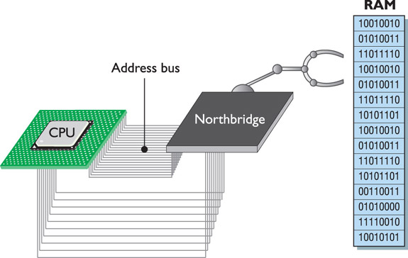
Simply placing a number of components into a computer is useless if the CPU can’t communicate with them. Getting the CPU to communicate with a device starts with some kind of interconnection—a communication bus that enables the CPU to send commands to and from devices. To make this connection, let’s promote the MCC, giving it extra firepower to act as not only the interconnection between the CPU and RAM, but also the interconnection between the CPU and the other devices on the PC. The MCC isn’t just the memory controller anymore, so let’s now call it the Northbridge because it acts as the primary bridge between the CPU and the rest of the computer (see Figure 8-1).
Figure 8-1 Meet the Northbridge
Your PC uses so many devices, the PC industry decided to delegate some of the interconnectivity work to a second chip called the Southbridge. The Northbridge deals with high-speed interfaces such as the connection to your video card and RAM. The Southbridge works mainly with lower-speed devices such as the USB controller and hard drive controllers. Chip makers design matched sets of particular models of Northbridge and Southbridge to work together. You don’t buy a Northbridge from one company and a Southbridge from another—they’re sold as a set. We call this set of Northbridge and Southbridge the chipset.
 EXAM TIP Modern processors include the functions of the Northbridge directly on the CPU. The Southbridge is now called the Input/Output Controller Hub (ICH) in new Intel systems and the Fusion Controller Hub (FCH) in new AMD systems. To help you understand their function, however, I’ll still refer to the Northbridge and Southbridge as distinct elements.
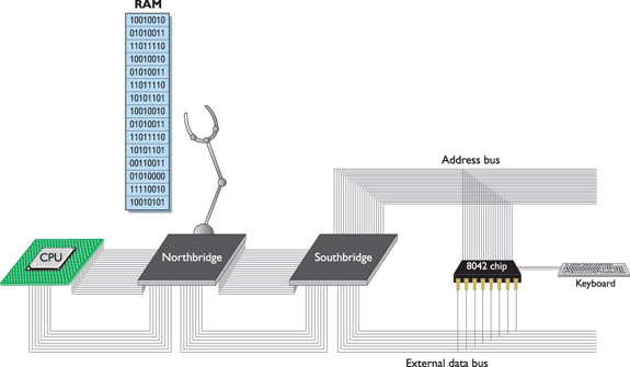
The chipset extends the data bus to every device on the PC. The CPU uses the data bus to move data to and from all of the devices of the PC. Data constantly flows on the external data bus among the CPU, chipset, RAM, and other devices on the PC (see Figure 8-2).
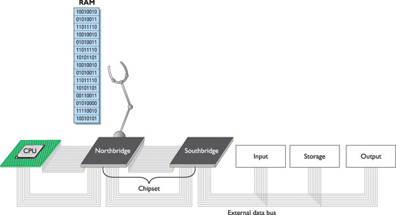
Figure 8-2 The chipset extending the data bus
The first use for the address bus, as you know, is for the CPU to tell the chipset to send or store data in memory and to tell the chipset which section of memory to access or use. Just as with the external data bus, the chipset extends the address bus to all of the devices (see Figure 8-3). That way, the CPU can use the address bus to send commands to devices, just as it sends commands to the chipset.
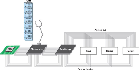
Figure 8-3 Every device in your computer connects to the address bus.
It’s not too hard to swallow the concept that the CPU uses the address bus to talk to devices, but how does it know what to say to them? How does it know all of the patterns of ones and zeros to place on the address bus to tell the hard drive it needs to send a file? Let’s look at the interaction between the keyboard and CPU for insight into this process.
The keyboard provides a great example of how the buses and support programming help the CPU get the job done. In early computers, the keyboard connected to the external data bus via a special chip known as the keyboard controller. Don’t bother looking for this chip on your motherboard—the Southbridge now handles keyboard controller functions. The way the keyboard controller—or technically, the keyboard controller circuitry—works with the CPU, however, has changed only a small amount in the past 25+ years, making it a perfect tool to illustrate how the CPU talks to a device.
 NOTE Techs commonly talk about various functions of the chipset as if those functions were still handled by discrete chips. So you’ll hear about memory controllers, keyboard controllers, mouse controllers, USB controllers, and so on, even though they’re all just circuits on the Northbridge or Southbridge.
The keyboard controller was one of the last single-function chips to be absorbed into the chipset. For many years—in fact, well into the Pentium III/Early Athlon era—most motherboards had separate keyboard controller chips. Figure 8-4 shows a typical keyboard controller from those days. Electronically, it looked like Figure 8-5.

Figure 8-4 A keyboard chip on a Pentium motherboard
Figure 8-5 Electronic view of the keyboard controller
NOTE Even though the model numbers changed over the years, you’ll still hear techs refer to the keyboard controller as the 8042, after the original keyboard controller chip.
Every time you press a key on your keyboard, a scanning chip in the keyboard notices which key you pressed. Then the scanner sends a coded pattern of ones and zeros—called the scan code—to the keyboard controller. Every key on your keyboard has a unique scan code. The keyboard controller stores the scan code in its own register. Does it surprise you that the lowly keyboard controller has a register similar to a CPU? Lots of chips have registers—not just CPUs (see Figure 8-6).

Figure 8-6 Scan code stored in keyboard controller’s register
How does the CPU get the scan code out of the keyboard controller (see Figure 8-7)? While we’re at it, how does the CPU tell the keyboard to change the typematic buffer rate (when you hold down a key and the letter repeats) or to turn the number lock LED on and off, to mention just a few other jobs the keyboard needs to do for the system? The point is that the keyboard controller must be able to respond to multiple commands, not just one.

Figure 8-7 The CPU ponders the age-old dilemma of how to get the 8042 to cough up its data.
The keyboard controller accepts commands exactly as you saw the CPU accept commands in Chapter 6. Remember when you added 2 to 3 with the 8088? You had to use specific commands from the 8088’s codebook to tell the CPU to do the addition and then place the answer on the external data bus. The keyboard controller has its own codebook—much simpler than any CPU’s codebook, but conceptually the same. If the CPU wants to know what key was last pressed on the keyboard, the CPU needs to know the command (or series of commands) that orders the keyboard controller to put the scan code of the letter on the external data bus so the CPU can read it.
The CPU doesn’t magically or otherwise automatically know how to talk with any device; it needs some sort of support programming loaded into memory that teaches it about a particular device. This programming is called basic input/output services (BIOS). The programs dedicated to enabling the CPU to communicate with devices are called services (or device drivers, as you’ll see later in the chapter). This goes well beyond the keyboard, by the way. In fact, every device on the computer needs BIOS! But let’s continue with the keyboard for now.
A talented programmer could write BIOS for a keyboard if the programmer knew the keyboard’s codebook; keyboards are pretty simple devices. This begs the question: where would this support programming be stored? Well, programming could be incorporated into the operating system. Storing programming to talk to the hardware of your PC in the operating system is great—all operating systems have built-in code that knows how to talk to your keyboard, your mouse, and just about every piece of hardware you may put into your PC.
That’s fine once the operating system’s up and running, but what about a brand new stack of parts you’re about to assemble into a new PC? When a new system’s being built, it has no operating system. The CPU must have access to BIOS for the most important hardware on your PC: not only the keyboard, but also the monitor, hard drives, optical drives, USB ports, and RAM. This code can’t be stored on a hard drive or optical disc—these important devices need to be ready at any time the CPU calls them, even before installing a mass storage device or an operating system.
The perfect place to store the support programming is on the motherboard. That settles one issue, but another looms: What storage medium should the motherboard use? DRAM won’t work, because all of the data would be erased every time you turned off the computer. You need some type of permanent program storage device that does not depend on other peripherals to work. And you need that storage device to sit on the motherboard.
Motherboards store the keyboard controller support programming, among other programs, on a special type of device called a read-only memory (ROM) chip. A ROM chip stores programs, called services, exactly like RAM: that is, like an 8-bit-wide spreadsheet. But ROM differs from RAM in two important ways. First, ROM chips are nonvolatile, meaning that the information stored on ROM isn’t erased when the computer is turned off. Second, traditional ROM chips are read-only, meaning that once you store a program on one, you can’t change it. Modern motherboards use a type of ROM called flash ROM that differs from traditional ROM in that you can update and change the contents through a very specific process called “flashing the ROM,” covered later in this chapter. Figure 8-8 shows a typical flash ROM chip on a motherboard. When the CPU wants to talk to the keyboard controller, it goes to the flash ROM chip to access the proper programming.

Figure 8-8 Typical flash ROM
Every motherboard has a flash ROM chip, called the system ROM chip because it contains code that enables your CPU to talk to the basic hardware of your PC (see Figure 8-9). As alluded to earlier, the system ROM holds BIOS for more than just the keyboard controller. It also stores programs for communicating with the floppy drive, hard drives, optical drives, display devices, USB ports, and other basic devices on your motherboard.
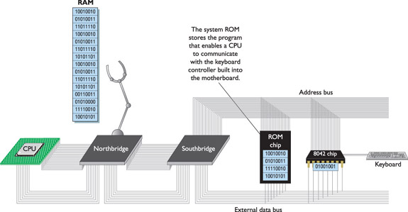
Figure 8-9 Function of the flash ROM chip
To talk to all of that hardware requires hundreds of little services (2 to 30 lines of code each). These hundreds of little programs stored on the system ROM chip on the motherboard are called, collectively, the system BIOS (see Figure 8-10). Techs call programs stored on ROM chips of any sort firmware.

Figure 8-10 CPU running BIOS service
The system ROM chips used on modern PCs store as much as 2 MB of programs, although only 65,536 bytes are used to store the system BIOS. This allows for backward compatibility with earlier systems. The rest of the ROM space is put to good use doing other jobs.
EXAM TIP Programs stored on ROM chips—flash or any other kind of ROM chip—are known collectively as firmware, as opposed to programs stored on erasable media, which are collectively called software.
Every system BIOS has two types of hardware to support. First, the system BIOS supports all of the hardware that never changes, such as the keyboard. (You can change your keyboard, but you can’t change the keyboard controller built into the Southbridge.) Another example of hardware that never changes is the PC speaker (the tiny one that beeps at you, not the ones that play music). The system ROM chip stores the BIOS for these and other devices that never change.
Second, the system BIOS supports all of the hardware that might change from time to time. This includes RAM (you can add RAM), hard drives (you can replace your hard drive with a larger drive or add a second hard drive), and floppy drives (you can add another floppy drive, although that’s not common today). The system ROM chip stores the BIOS for these devices, but the system needs another place to store information about the specific details of a piece of hardware. This enables the system to differentiate between a Western Digital Caviar Black 1.5-TB hard drive and a Seagate Barracuda 1-TB drive, and yet still support both drives right out of the box.
A separate memory chip, called the complementary metal-oxide semiconductor (CMOS) chip, stores the information that describes specific device parameters. CMOS does not store programs; it only stores data that is read by BIOS to complete the programs needed to talk to changeable hardware. CMOS also acts as a clock to keep the current date and time.
Years ago, CMOS was a separate chip on the motherboard, as shown in Figure 8-11. Today, the CMOS is almost always built into the Southbridge.
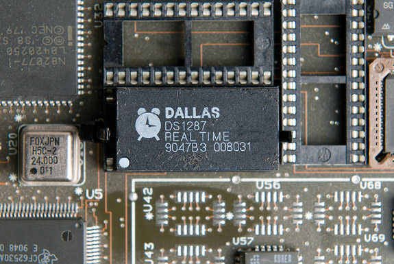
Figure 8-11 Old-style CMOS
Most CMOS chips store around 64 KB of data, but the PC usually needs only a very small amount—about 128 bytes—to store all of the necessary information on the changeable hardware. Don’t let the tiny size fool you. The information stored in CMOS is absolutely necessary for the PC to function!
If the data stored on CMOS about a particular piece of hardware (or about its fancier features) is different from the specs of the actual hardware, the computer cannot access that piece of hardware (or use its fancier features). It is crucial that this information be correct. If you change any of the previously mentioned hardware, you must update CMOS to reflect those changes. You need to know, therefore, how to change the data on CMOS.
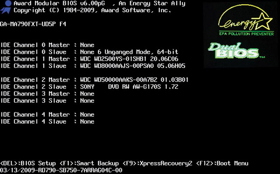
Every PC ships with a program built into the system ROM called the CMOS setup program or the system setup utility that enables you to access and modify CMOS data. When you fire up your computer in the morning, the first thing you likely see is the BIOS information. It might look like the example shown in Figure 8-12 or perhaps like the example shown in Figure 8-13.
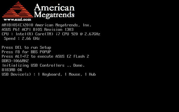
Figure 8-12 AMI BIOS information
Figure 8-13 Award/Phoenix BIOS information
NOTE The terms CMOS setup program, CMOS, and system setup utility are functionally interchangeable today. You’ll even hear the program referred to as the BIOS setup utility. Most techs just call it the CMOS.
Who or what is AMIBIOS, and who or what is Phoenix Technologies? These are brand names of BIOS companies. They write BIOS programs and sell them to computer manufacturers. In today’s world, motherboard makers rarely write their own BIOS. Instead, they buy their BIOS from specialized third-party BIOS makers such as Award Software and Phoenix Technologies. Although several companies write BIOS, two big companies control 99 percent of the BIOS business: American Megatrends (AMI) and Phoenix Technologies. Phoenix bought Award Software and still sells the Award brand name as a separate product line. These three are the most common brand names in the field.
You always access a system’s CMOS setup program at boot. The real question is how to access the CMOS setup at boot for your particular PC. AMI, Award, and Phoenix use different keys to access the CMOS setup program. Usually, BIOS manufacturers tell you how to access the CMOS setup right on the screen as your computer boots. For example, at the bottom of the screen in Figure 8-13, you are instructed to “press the DEL key to enter BIOS Setup.” Keep in mind that this is only one possible example. Motherboard manufacturers can change the key combinations for entering CMOS setup. You can even set up the computer so the message does not show—a smart idea if you need to keep nosy people out of your CMOS setup! If you don’t see an “enter setup” message, wait until the RAM count starts and then try one of the following keys or key combinations: DEL, ESC, Fl, F2, CTRL-ALT-ESC, CTRL-ALT-INS, CTRL-ALT-ENTER, Or CTRL-S. It may take a few tries, but you will eventually find the right key or key combination. If not, check the motherboard book or the manufacturer’s Web site for the information.
Okay, I’ve thrown a whole bunch of terms at you describing various pieces of hardware and software and what does what to whom. Here’s the scorecard so you can sort out the various pieces of data.
1. The system ROM chip stores the system BIOS, programs needed by the CPU to communicate with devices.
2. The system ROM chip also holds the program that accesses the information stored on the CMOS chip to support changeable pieces of hardware. This program is called the CMOS setup program or the system setup utility.
3. The CMOS holds a small amount of data that describes the changeable pieces of hardware supported by the system BIOS. The CMOS today is a part of the Southbridge.
Got all that? Let’s take a quick tour of a CMOS setup program.
Every BIOS maker’s CMOS setup program looks a little different, but don’t let that confuse you. They all contain basically the same settings; you just have to be comfortable poking around. To avoid doing something foolish, do not save anything unless you are sure you have it set correctly.
As an example, let’s say your machine has Award BIOS. You boot the system and press DEL to enter CMOS setup. The screen shown in Figure 8-14 appears. You are now in the main menu of the Award CMOS setup program. The setup program itself is stored on the ROM chip, but it edits only the data on the CMOS chip.
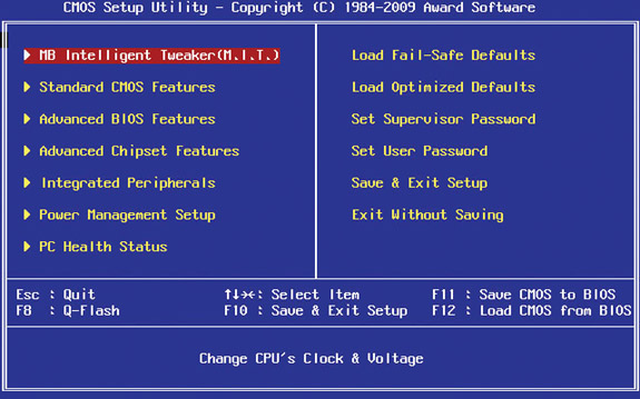
Figure 8-14 Typical CMOS main screen by Award
If you select the Standard CMOS Features option, the Standard CMOS Features screen appears (see Figure 8-15). On this screen you can change floppy drive, hard drive, and optical drive settings, as well as the system’s date and time. You will learn how to set up the CMOS for these devices in later chapters. At this point, your only goal is to understand CMOS and know how to access the CMOS setup on your PC, so don’t try to change anything yet. If you have a system that you are allowed to reboot, try accessing the CMOS setup now.

Figure 8-15 Standard CMOS Features screen
 CAUTION Accessing the CMOS setup utility for a system is perfectly fine, but do not make changes unless you fully understand that system!
Does it look anything like these examples? If not, can you find the screen that enables you to change the floppy drives, hard drives, and optical drives? Trust me, every CMOS setup has that screen somewhere! Figure 8-16 shows the same standard CMOS setup screen on a system with Phoenix BIOS. Note that this CMOS setup utility calls this screen “Main.”
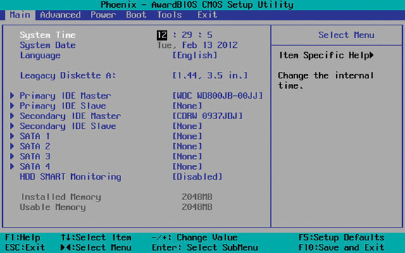
Figure 8-16 Phoenix BIOS CMOS setup utility Main screen
The first BIOS was nothing more than this standard CMOS setup. Today, all computers have many extra CMOS settings. They control items such as memory management, password and booting options, diagnostic and error handling, and power management. The following section takes a quick tour of an Award CMOS setup program. Remember that your CMOS setup almost certainly looks at least a little different from mine, unless you happen to have the same BIOS. The chances of that happening are quite slim.
Phoenix has virtually cornered the desktop PC BIOS market with its Award Modular BIOS. Motherboard makers buy a boilerplate BIOS, designed for a particular chipset, and add or remove options (Phoenix calls them modules) based on the needs of each motherboard. This means that seemingly identical CMOS setup utilities can be extremely different. Options that show up on one computer might be missing from another. Compare the older Award screen in Figure 8-17 with the more modern Award CMOS screen in Figure 8-14. Figure 8-17 looks different—and it should—as this much older system simply doesn’t need the extra options available on the newer system.
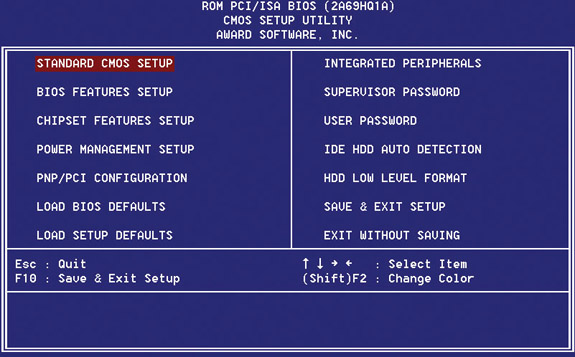
Figure 8-17 Older Award setup screen
NOTE All of these screens tend to overwhelm new techs. When they first encounter the many options, some techs feel they need to understand every option on every screen to configure CMOS properly. Relax—if I don’t talk about a particular CMOS setting somewhere in this book, it’s probably not important, either for the CompTIA A+ certification exams or to a real tech.
The next section starts the walkthrough of a CMOS setup utility with the MB Intelligent Tweaker, followed by some of the Advanced screens. Then you’ll go through other common screens, such as Integrated Peripherals, Power, and more.
You can use MB Intelligent Tweaker (M.I.T.) to change the voltage and multiplier settings on the motherboard for the CPU from the defaults. Motherboards that cater to overclockers tend to have this option. Usually you just set this to Auto or Default and stay away from this screen (see Figure 8-18).
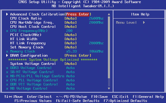
Figure 8-18 MB Intelligent Tweaker (M.I.T.)
NOTE In Advanced BIOS Features, you might also find several diagnostic tools. I’ll discuss a common hard drive diagnostic tool, the Self-Monitoring, Analysis and Reporting Technology (S.M.A.R.T.), in Chapter 11.
Advanced BIOS Features is the dumping ground for all of the settings that aren’t covered in the Standard menu and don’t fit nicely under any other screen. This screen varies wildly from one system to the next. You most often use this screen to select the boot options (see Figure 8-19).
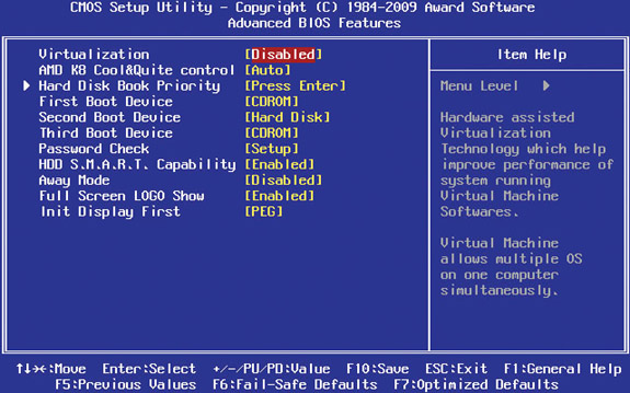
Figure 8-19 Advanced BIOS Features
You’ve already learned a lot about how an operating system interacts with hardware and software, but did you know you can also recreate an entire PC (including the hardware, software, and operating system) virtually as a program on your PC? A virtual machine is a powerful type of program that enables you to run a second (or third or fourth), software-based machine inside your physical PC. It recreates the motherboard, hard drives, RAM, network adapters, and more, and is just as powerful as a real PC. To run these virtual machines, however, you’ll need a very powerful PC—you are trying to run multiple PCs at the same time, after all.
To support this, CPU manufacturers have added hardware-assisted virtualization. Intel calls their version Intel Virtualization Technology, and AMD calls theirs AMD Virtualization Technology—perhaps the only time these two companies have agreed on a name. This technology helps the virtual machines use your hardware more efficiently and is controlled by the BIOS. This feature is off by default in BIOS, so if your virtual machine requires hardware-assisted virtualization, you’ll need to activate it here.
Many motherboards support the chassis intrusion detection feature provided by the computer case, or chassis. Compatible cases contain a switch that trips when someone opens the case. With motherboard support and a proper connection between the motherboard and the case, the CMOS logs whether the case has been opened and, if it has, posts a notification to the screen on the subsequent boot. How cool is that?
The Advanced Chipset Features screen (see Figure 8-20) strikes fear into most everyone, because it deals with extremely low-level chipset functions. Avoid this screen unless a high-level tech (such as a motherboard maker’s support tech) explicitly tells you to do something in here.
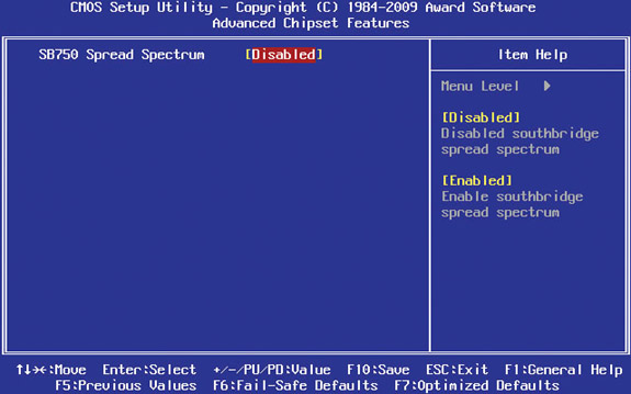
Figure 8-20 Advanced Chipset Features
You will use the Integrated Peripherals screen quite often. Here you configure, enable, or disable the onboard devices, such as the integrated sound card (see Figure 8-21).
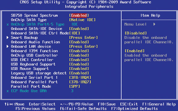
Figure 8-21 Integrated Peripherals
As the name implies, you can use the Power Management Setup screen (see Figure 8-22) to set up the power management settings for the system. These settings work in concert (sometimes in conflict) with Windows’ power management settings to control how and when devices turn off and back on to conserve power.
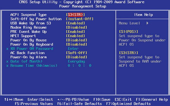
Figure 8-22 Power Management Setup
Many PCs have CMOS setup menus that display information about the CPU, RAM, and GPU and include controls for overclocking them. You learned about overclocking in Chapter 6, so you already know what it does and how dangerous it can be. Overclocking works by changing the bus speeds, clock multipliers, and voltage for the desired component. Be very careful when overclocking or you could end up with a dead CPU!
EXAM TIP When overclocking your PC, look for settings that adjust the CPU’s clock and bus speeds. The higher you push these, the faster your PC will go.
All CMOS setup utilities come with menu items that are for the most part no longer needed, but no one wants to remove them. The PnP/PCI Configurations screen is a perfect example (see Figure 8-23). Plug and play (PnP) is how devices automatically work when you snap them into your PC. PCI is a type of slot used for cards. Odds are very good you’ll never deal with this screen.
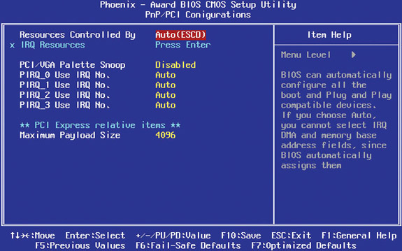
Figure 8-23 PnP/PCI Configurations
The other options on the main menu of an Award CMOS do not have their own screens. Rather, these simply have small dialog boxes that pop up, usually with “Are you sure?” messages. The Load Fail-Safe/Optimized default options keep you from having to memorize all of those weird settings you’ll never touch. Fail-Safe sets everything to very simple settings—you might occasionally use this setting when very low-level problems such as freeze-ups occur and you’ve checked more obvious areas first. Optimized sets the CMOS to the best possible speed/stability for the system. You would use this option after you’ve tampered with the CMOS too much and need to put it back like it was!
Many CMOS setup programs enable you to set a password in CMOS to force the user to enter a password every time the system boots. Don’t confuse this with the Windows logon password. This CMOS password shows up at boot, long before Windows even starts to load. Figure 8-24 shows a typical CMOS password prompt.
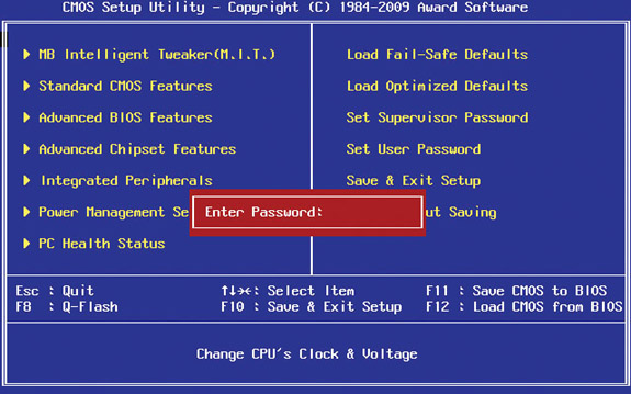
Figure 8-24 CMOS password prompt
Some CMOS setup utilities enable you to create two passwords: one for boot and another for accessing the CMOS setup program. This extra password just for entering CMOS setup is a godsend in schools, for example, where non-techs tend to wreak havoc in areas (such as CMOS) that they should not access!
Many CMOS setup utilities also enable you to monitor CPU temperature, system temperature, and the voltages of the CPU and RAM. This menu, usually called PC Health Status, also enables you to change fan speeds. A system will almost always handle those on its own, but if you’re setting up a home theater PC and you want the quietest system possible, you can go in and set the fans to the lowest speed.
EXAM TIP On some motherboards, the CMOS setup program enables you to control the ATA Security Mode Feature Set, also commonly referred to as drive lock or DriveLock. ATA Security Mode is the first line of defense for protecting hard disks from unwanted access when a system is lost or stolen.
Some PC manufacturers also include LoJack security features in their BIOS—this way, if your PC is stolen, you can track its location, install a key logger, or even remotely shut down your computer.
The Trusted Platform Module (TPM) acts as a secure cryptoprocessor, which is to say that it is a hardware platform for the acceleration of cryptographic functions and the secure storage of associated information. The specification for the TPM is published by the Trusted Computing Group, an organization whose corporate members include Intel, Microsoft, AMD, IBM, Lenovo, Dell, Hewlett-Packard, and many others.
The TPM can be a small circuit board plugged into the motherboard, or it can be built directly into the chipset. The CMOS setup program usually contains settings that can turn the TPM on or off and enable or disable it.
TPMs can be used in a wide array of cryptographic operations, but one of the most common uses of TPMs is hard disk encryption. For example, the BitLocker Drive Encryption feature of Microsoft’s Windows Vista and Windows 7 can be accelerated by a TPM, which is more secure because the encryption key is stored in the tamper-resistant TPM hardware rather than on an external flash drive. Other possible uses of TPMs include digital rights management (DRM), network access control, application execution control, and password protection.
Of course, all CMOS setups provide some method to Save and Exit or to Exit Without Saving. Use these as needed for your situation. Exit Without Saving is particularly nice for those folks who want to poke around the CMOS setup utility but don’t want to mess anything up. Use it!
The CMOS setup utility would meet all of the needs of a modern system for BIOS if manufacturers would just stop creating new devices. That’s not going to happen, of course, so let’s turn now to devices that need to have BIOS loaded from elsewhere.
Every piece of hardware in your computer needs some kind of programming that tells the CPU how to talk to that device. When IBM invented the PC more than 30 years ago, they couldn’t possibly have included all of the necessary BIOS routines for every conceivable piece of hardware on the system ROM chip. How could they? Most of the devices in use today didn’t exist on the first PCs. When programmers wrote the first BIOS, for example, network cards, mice, and sound cards did not exist. Early PC designers at IBM understood that they could not anticipate every new type of hardware, so they gave us a few ways to add programming other than on the BIOS. I call this BYOB—Bring Your Own BIOS. You can BYOB in two ways: option ROM and device drivers. Let’s look at both.
The first way to BYOB is to put the BIOS on the hardware device itself. Look at the card displayed in Figure 8-25. This is a serial ATA RAID hard drive controller—basically just a card that lets you add more hard drives to a PC. The chip in the center with the wires coming out the sides is a flash ROM that stores BIOS for the card. The system BIOS does not have a clue about how to talk to this card, but that’s okay, because this card brings its own BIOS on what’s called an option ROM chip.
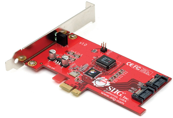
Figure 8-25 Option ROM
Most BIOS that come on option ROMs tell you that they exist by displaying information when you boot the system. Figure 8-26 shows a typical example of an option ROM advertising itself.

Figure 8-26 Option ROM at boot
In the early days of the PC, you could find all sorts of devices with BIOS on option ROMs. Today, option ROMs have mostly been replaced by more flexible software methods (more on device driver software in the next section), with one major exception: video cards. Every video card made today contains its own BIOS. Option ROMs work well but are hard to upgrade. For this reason, most hardware relies on software for BYOB.
A device driver is a file stored on the PC’s hard drive that contains all of the commands necessary to talk to whatever device it was written to support. All operating systems employ a method of loading these device drivers into RAM every time the system boots. They know which device drivers to install by reading a file (or files) that lists which device drivers the system needs to load at boot time. All operating systems are designed to look at this list early on in the boot process and copy the listed files into RAM, thereby giving the CPU the capability to communicate with the hardware supported by the device driver. Device drivers come with the device when you buy it. When you buy a sound card, for example, it comes with a disc that holds all of the necessary device drivers (and usually a bunch of extra goodies). The generic name for this type of CD-ROM is installation disc. In most cases, you install a new device, start the computer, and wait for Windows to prompt you for the installation disc (see Figure 8-27).
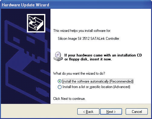
Figure 8-27 Windows asking for the installation disc
You might want to add or remove device drivers manually at times. Windows uses a special database called the Registry that stores everything you want to know about your system, including the device drivers. You shouldn’t access the Registry directly to access these drivers, but instead use the venerable Device Manager utility (discussed in Chapter 4).
As you should now understand, every piece of hardware on a system must have an accompanying program that provides the CPU with the code necessary to communicate with that particular device. This code may reside on the system ROM on the motherboard, on ROM on a card, or in a device driver file on the hard drive loaded into RAM at boot. BIOS is everywhere on your system, and you need to deal with it occasionally.
BIOS isn’t the only program on your system ROM. When the computer is turned on or reset, it initiates a special program, also stored on the system ROM chip, called the power-on self test (POST). The POST program checks out the system every time the computer boots. To perform this check, the POST sends out a command that says to all of the devices, “Check yourselves out!” All of the standard devices in the computer then run their own internal diagnostic—the POST doesn’t specify what they must check. The quality of the diagnostic is up to the people who made that particular device.
Let’s consider the POST for a moment. Suppose some device—let’s say it’s the keyboard controller chip—runs its diagnostic and determines that it is not working properly. What can the POST do about it? Only one thing really: tell the human in front of the PC! So how does the computer tell the human? PCs convey POST information to you in two ways: beep codes and text messages.
The computer tests the most basic parts of the computer first, up to and including the video card. In early PCs, you’d hear a series of beeps—called beep codes—if anything went wrong. By using beep codes before and during the video test, the computer could communicate with you. (If a POST error occurs before the video is available, obviously the error must manifest itself as beeps, because nothing can display on the screen.) The meaning of the beep code you’d hear varied among different BIOS manufacturers. You could find the beep codes for a specific motherboard in its motherboard manual.
Most modern PCs have only two beep codes: one for bad or missing video (one long beep followed by two or three short beeps), and one for bad or missing RAM (a single beep that repeats indefinitely).
CAUTION You’ll find lots of online documentation about beep codes, but it’s usually badly outdated.
You’ll hear three other beep sequences on most PCs (although they’re not officially beep codes). At the end of a successful POST, the PC produces one or two short beeps, simply to inform you that all is well. Most systems make a rather strange noise when the RAM is missing or very seriously damaged. Unlike traditional beep codes, this code repeats until you shut off the system. Finally, your speaker might make beeps for reasons that aren’t POST or boot related. One of the more common is a series of short beeps after the system’s been running for a while. That’s a CPU alarm telling you the CPU is approaching its high heat limit.
After the video has tested okay, any POST errors display on the screen as text errors. If you get a text error, the problem is usually, but not always, self-explanatory (see Figure 8-28). Text errors are far more useful than beep codes, because you can simply read the screen to determine the bad device.
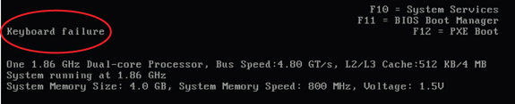
Figure 8-28 POST text error messages
Beep codes, numeric codes, and text error codes, although helpful, can sometimes be misleading. Worse than that, an inoperative device can sometimes disrupt the POST, forcing the machine into an endless loop. This causes the PC to act dead—no beeps and nothing on the screen. In this case, you need a device, called a POST card, to monitor the POST and identify which piece of hardware is causing the trouble.
POST cards are simple cards that snap into expansion slots on your system. A small, two-character light-emitting diode (LED) readout on the card indicates which device the POST is currently testing (see Figure 8-29).
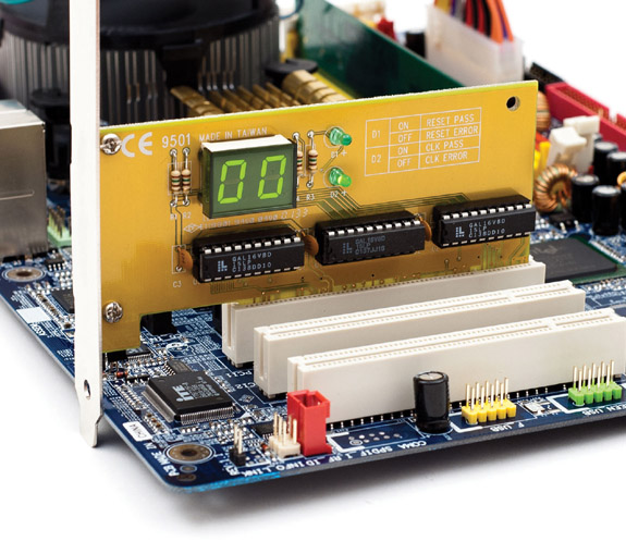
Figure 8-29 POST card in action
POST cards used to be essential tools for techs, but today I use them only when I have a “dead” PC to determine at which level it’s dead. If the POST card shows no reading, I know the problem is before the POST and must be related to the power, the CPU, the RAM, or the motherboard. If the board posts, then I know to look at more issues, such as the drives and so on.
All PCs need a process to begin their operations. Once you feed power to the PC, the tight interrelation of hardware, firmware, and software enables the PC to start itself, to “pull itself up by the bootstraps” or boot itself.
When you first power on the PC, the power supply circuitry tests for proper voltage and then sends a signal down a special wire called the power good wire to awaken the CPU. The moment the power good wire wakes it up, every CPU immediately sends a built-in memory address via its address bus. This special address is the same on every CPU, from the oldest 8086 to the most recent microprocessor. This address is the first line of the POST program on the system ROM! That’s how the system starts the POST. After the POST has finished, there must be a way for the computer to find the programs on the hard drive to start the operating system. The POST passes control to the last BIOS function: the bootstrap loader. The bootstrap loader is little more than a few dozen lines of BIOS code tacked to the end of the POST program. Its job is to find the operating system. The bootstrap loader reads CMOS information to tell it where to look first for an operating system. Your PC’s CMOS setup utility has an option that you configure to tell the bootstrap loader which devices to check for an operating system and in which order (see Figure 8-30).
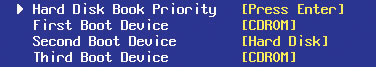
Figure 8-30 CMOS boot order
Almost all storage devices—floppy disks, hard disks, CDs, DVDs, and even USB thumb drives—can be configured to boot an operating system by setting aside a specific location called the boot sector. If the device is bootable, its boot sector contains special programming designed to tell the system where to locate the operating system. Any device with a functional operating system is called a bootable disk or a system disk. If the bootstrap loader locates a good boot sector, it passes control to the operating system and removes itself from memory. If it doesn’t, it goes to the next device in the boot order you set in the CMOS setup utility. Boot order is an important tool for techs because you can set it to load in special bootable devices so you can run utilities to maintain PCs without using the primary operating system.
Some BIOS include a feature that enables a PC to use a preboot execution environment (PXE). A PXE enables you to boot a PC without any local storage by retrieving an OS from a server over a network. You’ll see more on PXE when we talk about installing Windows in Chapter 14.
BIOS and CMOS are areas in your PC that you don’t go to very often. BIOS itself is invisible. The only real clue you have that it even exists is the POST. The CMOS setup utility, on the other hand, is very visible if you start it. Most CMOS setup utilities today work acceptably well without ever being touched. You’re an aspiring tech, however, and all self-respecting techs start up the CMOS setup utility and make changes. That’s when most CMOS setup utility problems take place.
If you mess with the CMOS setup utility, remember to make only as many changes at one time as you can remember. Document the original settings and the changes on a piece of paper so you can put things back if necessary. Don’t make changes unless you know what they mean! It’s easy to screw up a computer fairly seriously by playing with CMOS settings you don’t understand.
Your CMOS needs a continuous trickle charge to retain its data. Motherboards use some type of battery, usually a coin battery like those in wrist watches, to give the CMOS the charge it needs when the computer is turned off (see Figure 8-31). This battery also keeps track of the date and time when the PC is turned off.
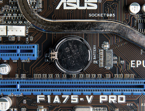
Figure 8-31 A CMOS battery
If the battery runs out of charge, you lose all of your CMOS information. If some mishap suddenly erases the information on the CMOS chip, the computer might not boot or you’ll get nasty-looking errors at boot. Any PC made after 2002 will boot to factory defaults if the CMOS clears, so the chances of not booting are slim—but you’ll still get errors at boot. Here are a few examples of errors that point to lost CMOS information:
• CMOS configuration mismatch
• CMOS date/time not set
• No boot device available
• CMOS battery state low
Here are some of the more common reasons for losing CMOS data:
• Pulling and inserting cards
• Touching the motherboard
• Dropping something on the motherboard
• Dirt on the motherboard
• Faulty power supplies
• Electrical surges
If you encounter any of these errors, or if the clock in Windows resets itself to January 1st every time you reboot the system, the battery on the motherboard is losing its charge and needs to be replaced. To replace the battery, use a screwdriver to pry the battery’s catch gently back. The battery should pop up for easy removal. Before you install the new battery, double-check that it has the same voltage and amperage as the old battery. To retain your CMOS settings while replacing the battery, simply leave your PC plugged into an AC outlet. The 5-volt soft power on all modern motherboards provides enough electricity to keep the CMOS charged and the data secure. Of course, I know you’re going to be extremely careful about ESD while prying up the battery from a live system!
Flash ROM chips can be reprogrammed to update their contents. With flash ROM, when you need to update your system BIOS to add support for a new technology, you can simply run a small command-line program, combined with an update file, and voilà, you have a new, updated BIOS! Different BIOS makers use slightly different processes for flashing the BIOS, but, in general, you insert a removable disk of some sort (usually a USB thumb drive) containing an updated BIOS file and use the updating utility in CMOS setup.
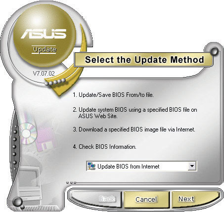
Some motherboard makers provide Windows-based flash ROM update utilities that check the Internet for updates and download them for you to install (see Figure 8-32). Most of these utilities also enable you to back up your current BIOS so you can return to it if the updated version causes trouble. Without a good backup, you could end up throwing away your motherboard if a flash BIOS update goes wrong, so you should always make one.
Figure 8-32 ROM-updating program for an ASUS motherboard
Finally, don’t update your BIOS unless you have some compelling reason to do so. As the old saying goes, “If it ain’t broke, don’t fix it!”
EXAM TIP While techs usually talk about “flashing the BIOS,” the CompTIA A+ exams refer to this process also as “installing firmware upgrades.”
Your computer’s system BIOS is one very old piece of programming. BIOS hasn’t changed much since it was conceived with the 286-based IBM AT computer back in the 1980s. As a result, BIOS works only in 16-bit mode and depends on x86-compliant hardware. In addition, if you have more than one operating system loaded on a single drive, you need one of those installed OSes to “take charge” and act as a boot loader.
If computing was going to move forward, a new type of BIOS needed to come along. Intel’s Extensible Firmware Interface (EFI) fills that role. In 2005, Intel released EFI for public standards, creating the Unified EFI forum to manage the specification. EFI was then renamed Unified Extensible Firmware Interface (UEFI).
 TIP Even though it’s really called UEFI, most techs use the term EFI.
UEFI acts as a super-BIOS, doing the same job as BIOS, but in a 32- or 64-bit environment. UEFI, though, does much more than just fill in for BIOS. Think of UEFI as a not yet extremely well-defined, industry-standard, mini-operating system that runs on top of the firmware of your computer, enabling you to do some pretty cool things at boot. Here are some of the things UEFI does:
• UEFI supports 32-bit or 64-bit booting.
• UEFI handles all boot-loading duties.
• UEFI is not dependent on x86 firmware.
UEFI became a standard years ago, so why did no one see a UEFI motherboard until 2011? The answer is simple: 3-TB hard drives. Regular BIOS will only boot to master boot record (MBR) drives, and MBR drives don’t support partitions greater than 2.2 TB. As 3-TB and larger drives began to appear in 2011, people using traditional BIOS discovered that strange issues popped up when they wanted to boot off of a 3-TB hard drive (see Figure 8-33). Instead of a 3-TB volume, you’d find a 2.2-TB volume and unpartitioned space.
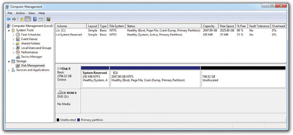
Figure 8-33 Here’s what happens when you install Windows 7 on a greater-than-2.2-TB drive using regular BIOS.
UEFI motherboards support booting a newer type of hard drive partitioning called GUID Partition Table (GPT) that supports partitions larger than 2.2 TB. If you want to boot off of a hard drive using a single partition greater than 2.2 TB, you must use a UEFI motherboard and the hard drive must be blank. If your system meets these two criteria, the Windows 7 installation routine will automatically make a GPT drive for you (see Figure 8-34).

Figure 8-34 Here’s what happens when you install Windows 7 on a greater-than-2.2-TB drive using UEFI.
NOTE While UEFI works both for 32-bit and 64-bit operating systems, Microsoft decided to enable UEFI support only for 64-bit editions of Windows 7.
Although the EFI folks clearly defined issues such as booting and accessing firmware, they didn’t define issues such as the graphical user interface or audio. If you think UEFI possesses a standard interface similar to the Windows desktop, forget it. Figure 8-35 shows an ASUS motherboard’s UEFI interface. UEFI serves as a non-hardware-specific, non-OS-specific, 32- or 64-bit bootloader. This doesn’t make things we know and love such as POST or system setup go away. They still exist, but now UEFI runs the show instead of BIOS (see Figure 8-36).
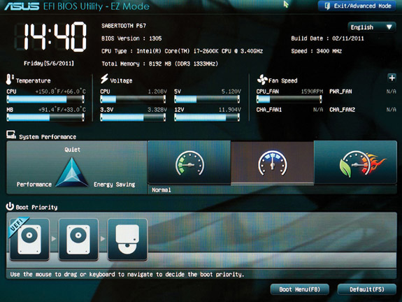
Figure 8-35 ASUS EFI BIOS Utility
Figure 8-36 POST and system setup are still here.
1. What does BIOS provide for the computer? (Choose the best answer.)
A. BIOS provides the physical interface for various devices such as USB and FireWire ports.
B. BIOS provides the programming that enables the CPU to communicate with other hardware.
C. BIOS provides memory space for applications to load into from the hard drive.
D. BIOS provides memory space for applications to load into from the main system RAM.
2. What is the correct boot sequence for a PC?
A. CPU, POST, power good, boot loader, operating system
B. POST, power good, CPU, boot loader, operating system
C. Power good, boot loader, CPU, POST, operating system
D. Power good, CPU, POST, boot loader, operating system
3. Jill decided to go retro and added a second floppy disk drive to her computer. She thinks she has it physically installed correctly, but it doesn’t show up in Windows. Which of the following options will most likely lead Jill where she needs to go to resolve the issue?
A. Reboot the computer and press the F key on the keyboard twice. This signals that the computer has two floppy disk drives.
B. Reboot the computer and watch for instructions to enter the CMOS setup utility (for example, a message may say to press the DELETE key). Do what it says to go into CMOS setup.
C. In Windows, press the DELETE key twice to enter the CMOS setup utility.
D. In Windows, go to Start | Run and type floppy. Click OK to open the Floppy Disk Drive Setup Wizard.
4. Henry bought a new card for capturing television on his computer. When he finished going through the packaging, though, he found no driver disc, only an application disc for setting up the TV capture software. After installing the card and software, it all works flawlessly. What’s the most likely explanation?
A. The device doesn’t need BIOS, so there’s no need for a driver disc.
B. The device has an option ROM that loads BIOS, so there’s no need for a driver disc.
C. Windows supports TV capture cards out of the box, so there’s no need for a driver disc.
D. The manufacturer made a mistake and didn’t include everything needed to set up the device.
5. Which of the following most accurately describes the relationship between BIOS and hardware?
A. All hardware needs BIOS.
B. All hardware that attaches to the motherboard via ribbon cables needs BIOS.
C. All hardware built into the motherboard needs BIOS.
D. Some hardware devices need BIOS.
6. After a sudden power outage, Samson’s PC rebooted, but nothing appeared on the screen. The PC just beeps at him, over and over and over. What’s most likely the problem?
A. The power outage toasted his RAM.
B. The power outage toasted his video card.
C. The power outage toasted his hard drive.
D. The power outage toasted his CPU.
7. Davos finds that a disgruntled former employee decided to sabotage her computer when she left by putting a password in CMOS that stops the computer from booting. What can Davos do to solve this problem?
A. Davos should boot the computer while holding the left SHIFT key. This will clear the CMOS information.
B. Davos should try various combinations of the former employee’s name. The vast majority of people use their name or initials for CMOS passwords.
C. Davos should find the CMOS clear jumper on the motherboard. Then he can boot the computer with a shunt on the jumper to clear the CMOS information.
D. Davos should find a replacement motherboard. Unless he knows the CMOS password, there’s nothing he can do.
8. Richard over in the sales department went wild in CMOS and made a bunch of changes that he thought would optimize his PC. Now most of his PC doesn’t work. The computer powers up, but he can only get to CMOS, not into Windows. Which of the following tech call answers would most likely get him up and running again?
A. Reboot the computer about three times. That’ll clear the CMOS and get you up and running.
B. Open up the computer and find the CMOS clear jumper. Remove a shunt from somewhere on the motherboard and put it on the CMOS clear jumper. Reboot and then put the shunt back where you got it. Reboot, and you should be up and running in no time.
C. Boot into the CMOS setup program and then find the option to load a plug-and-play operating system. Make sure it’s set to On. Save and exit CMOS; boot normally into Windows. You should be up and running in no time.
D. Boot into the CMOS setup program and then find the option to load Optimized Default settings. Save and exit CMOS; boot normally into Windows. You should be up and running in no time.
9. Jill boots an older Pentium III system that has been the cause of several user complaints at the office. The system powers up and starts to run through POST, but then stops. The screen displays a “CMOS configuration mismatch” error. Of the following list, what is the most likely cause of this error?
A. Dying CMOS battery
B. Bad CPU
C. Bad RAM
D. Corrupt system BIOS
10. Where does Windows store device drivers?
A. Computer
B. Hardware
C. Registry
D. Drivers and Settings
1. B. BIOS provides the programming that enables the CPU to communicate with other hardware.
2. D. Here’s the correct boot sequence: power good, CPU, POST, boot loader, operating system.
3. B. Jill should reboot the computer and watch for instructions to enter the CMOS setup utility (for example, a message may say to press the DELETE key). She should do what it says to go into CMOS setup.
4. B. Most likely the device has an option ROM, because it works.
5. A. All hardware needs BIOS!
6. A. The repeating beep and a dead PC most likely indicate a problem with RAM.
7. C. Davos should find the CMOS clear jumper on the motherboard and then boot the computer with a shunt on the jumper to clear the CMOS information.
8. D. Please don’t hand Richard a screwdriver! Having him load Optimized Default settings will most likely do the trick.
9. A. The CMOS battery is likely dying.
10. C. Windows stores device drivers in the Registry.