Chapter Seven
Let’s Do a Little Jig
Jigs are handy little devices that improve life by ensuring repeatable accuracy, making assembly faster and easier, or simply holding parts to free up your hands. The time it takes to make jigs is saved many times over while using them. During my years of machine shop and metal fabrication, I’ve made hundreds of jigs for different purposes. It was always one of the most fun and challenging parts of the job.
While jigs often are made for mass production, the ones shown here will come in handy even if you’re building only a couple of hives. After all, two 10-frame hives with two deep hive bodies each and just two supers means you’ll be assembling a minimum of 80 frames. That’s worth having a jig for.
Simple Bending Jig
I designed this simple jig for bending the aluminum flashing I used on telescoping covers (see page 52). I had the wood on hand and only needed to buy the hardware. For your own jig, you can keep things simple and stick with the basic design, or add one or more of the additional features described in Customizing Your Jig (page 90).
Either way, you’ll have a super-handy jig for bending light aluminum sheet metal. And even if you use it only for the first bend on your outer covers, you’ll be starting out with a good, clean bend that will make the rest of the installation easier.
Tools
- Table saw
- Drill press or portable drill
- 1"-diameter Forstner or spade bit
- 1⁄2" brad-point bit
Materials
- One 6-foot 5⁄4×5 board
- Three 1⁄2" × 3" carriage bolts with washers and wingnuts
- Epoxy (optional)
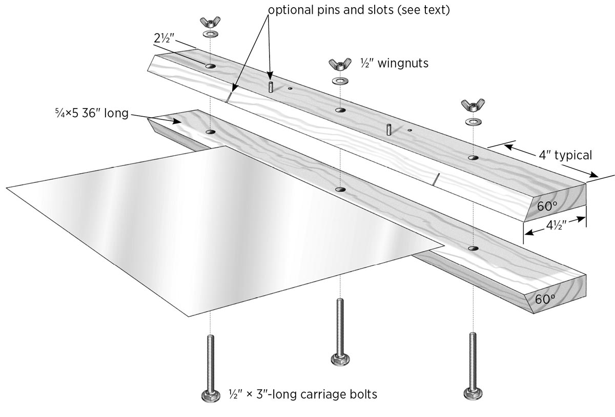
1. Cut the boards.
Cut the 5⁄4×5 board into two equal lengths. Use a table saw to cut a 60-degree angle lengthwise along the edge of both boards, as shown.
2. Add the carriage bolts.
Clamp the boards together with all edges aligned. On the bottom face of the bottom board, make three marks 21⁄2" from the back (square) edge: two at 4" from each end and one in the center. At each mark, drill a 1"-diameter hole to a depth of about 5⁄16" — enough to recess the carriage bolt head. Then, drill 1⁄2" holes all the way through both boards for the bolts.
Install the carriage bolts from the bottom. Add washers and wingnuts on top and tighten the bolts to set the bolt heads into the bottom board. If desired, you can also add a little epoxy on the heads (now or later) to keep the bolts from turning.
3. Use the jig.
To use the jig, simply mark your bend line onto the sheet metal and clamp the sheet between the two boards, tightening down the wing nuts. Hold the jig in both hands with the metal on a flat surface, then pivot the jig as you apply downward pressure.
Customizing Your Jig
There are a few options you can add to your jig to make it more useful and easier to use:
Slots. Once you bend up the first two opposite sides of a metal top at 90 degrees, those lips will hit the jig and get distorted when you try to bend the last two sides. To remedy this, cut vertical slots in the top board of the bending jig where those lips line up. Make those slots a little deeper than the height of the lips you are bending. Now, when you bend the last two sides of your cover, line the lips up with the slots, allowing you to bend all four sides for things like outer covers.
Stop pins. Add holes for stop pins at widths you will be bending frequently. To locate the holes, measure back the bending-width distance plus one-half the diameter of the pins you will use. For example, for a 1⁄2"-wide bend, using a 1⁄4" pin, you would drill 5⁄8" from the front of the jig. Drill through the top board and partway into the bottom board. Drop your pins in, and slide the sheet against them for repeat bends.
Springs. A couple of springs mounted between the boards automatically opens the jig when you loosen the wing nuts. You can buy small coil springs at hardware stores; they should be strong enough to push the boards apart but not so strong that it’s hard to tighten the wing nuts. Drill counterbore holes for the springs to set in.
Frame Assembly Jig
If you’ve decided to use only plastic frames, you can skip this project (or tear out one of its pages and use it as a bookmark). But if you’re anything like me and prefer the smell of freshly cut pine over the finest perfume, you’ll probably be assembling frames at some point in your beekeeping experience.
A jig for assembling frames doesn’t necessarily make the finished product come out better; it just makes the job a little easier and faster. The frame jig holds the end pieces upright and frees up your hands for the gluing and nailing (see photos on pages 116–117.)
You can make your jig hold any number of frames. I’ve seen many that hold 10 frames, and if you’re using an air nailer, setting up to do that many at once makes sense. I still do mine the old-fashioned way, with a hammer and nails, and my jig holds 5 frames at a time. With limited space on the workbench, this works out just right for me (see What Makes a Good Assembly Jig, on page 95).
Perhaps the best things about this jig are that no tools are required to use it, and once it’s assembled, there are only four parts to deal with. The construction does require some accurate cutting, but you can start it, say, after lunch, and you’ll be putting frames together by dinnertime. As always, I recommend that you read through the whole project before starting construction.
Tools
- Table saw
- Dial calipers, decimal type (see step 3)
- Small handsaw (such as a coping saw or hacksaw)
- Drill and combination drill/countersink bit
- Tin snips
Materials
- One 8-foot pine 1×4 (must be straight and square; see step 1)
- Scraps of pine 1-by lumber (about 12" long, for frame guides and spacers)
- Sixteen 3⁄4" wire nails
- Six 4d box nails
- Eight 11⁄4" deck screws
- Four 1⁄2" or 5⁄8" wire nails
- Eight 2" deck screws
- Wood glue
- One piece aluminum flashing or other thin sheet metal, approximately 2" × 4"
- One 11⁄2"-wide × 3"-long hinge with screws
1. Cut the main wood parts.
Note: When cutting the identical parts for this project, it’s best to use a stop to ensure the lengths of like parts are the same. This will make it easier to build your jig square. You can also substitute hardwood for increased strength.
Cut the following pieces to length from 1×4 lumber:
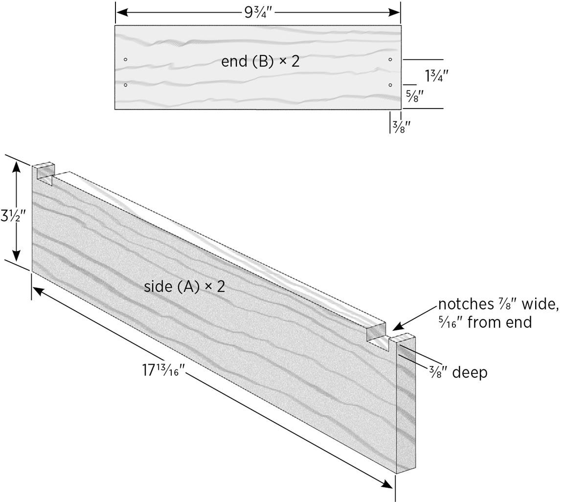
- Two sides (A) at 1713⁄16"
- Two ends (B) at 93⁄4"; rip each of these to 27⁄8" in width
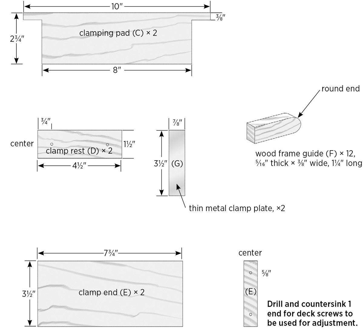
- Two clamping pads (C) at 10" (see step 5 for an optional cutting method)
- One piece at 41⁄2"; rip this piece into two 11⁄2"-wide pieces for the clamp rests (D)
- Two clamp ends (E) at 73⁄4"
Note: You will cut the frame guides (F) later.
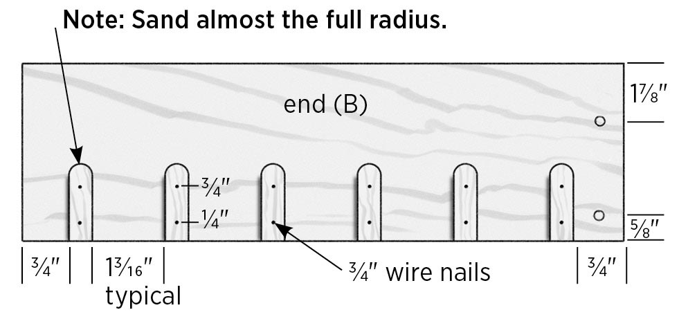
2. Notch the side pieces.
The sides (A) get two notches near each end that the clamping pads will set into. To cut the notches, set the table saw fence to 5⁄16" to the near side of the blade. Set the blade height to 3⁄8". Test-cut a scrap piece, then cut the notches, moving out the fence with each pass until the notches are 7⁄8" wide.
3. Cut the frame guides.
Note: The 12 frame guides (F) are small and must be cut carefully and accurately. Here’s how I cut mine.
Set the table saw fence at 3⁄8" and cut a test piece. Measure the cut piece with calipers (available at woodworking supply houses and many hardware stores), and adjust the fence as needed so it’s within 0.005" of 0.375" (3⁄8"). Set a 12"-long 1-by board on-edge against the fence with the saw blade set to just over 3⁄8" high, and make a full-length cut on each long edge.
Raise the saw blade above 3⁄8", nudge the fence in to about 5⁄16", and lay the board down with the saw cut you just made facing the fence, so that this second cut will cut out the strip. The width isn’t fussy as long as it’s less than 3⁄8" (the thickness of the frame ends). You will now have a 3⁄8" × 5⁄16" strip. With the wide end of the strip on the table, draw a line along the length for reference during assembly. Sand the edges of this strip, then use a small handsaw to cut 12 frame guides to length at 11⁄4". On one end of each strip, round over the narrow edges with sandpaper. This will help guide the ends of the frames as you slide them into the jig for assembly.
Work tip: When I had my first two hives built and my bees were on order, I spent a few winter nights sitting on the floor by the heater, gluing and nailing frames together one at a time. I have to say that I enjoyed it, and still do, although I’ve found that it’s easier on the back to stand or sit at my workbench.
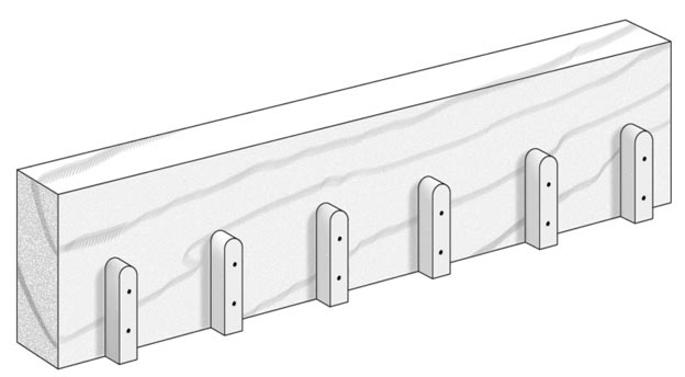
4. Install the frame guides.
Unplug the saw, tighten the fence, and place the two end pieces side-by-side, with their ends against the fence. Set a scrap piece of 3⁄4" wood on-edge on top of them and against the fence. Place one frame guide (F) on each end piece, tight against the block, and fasten the guide to the end with glue and 3⁄4" wire nails. This ensures the guides on both boards will line up properly when you assemble the jig.
Install the remaining frame guides, using the 13⁄16" spacer strip to set gaps between each pair of guides.
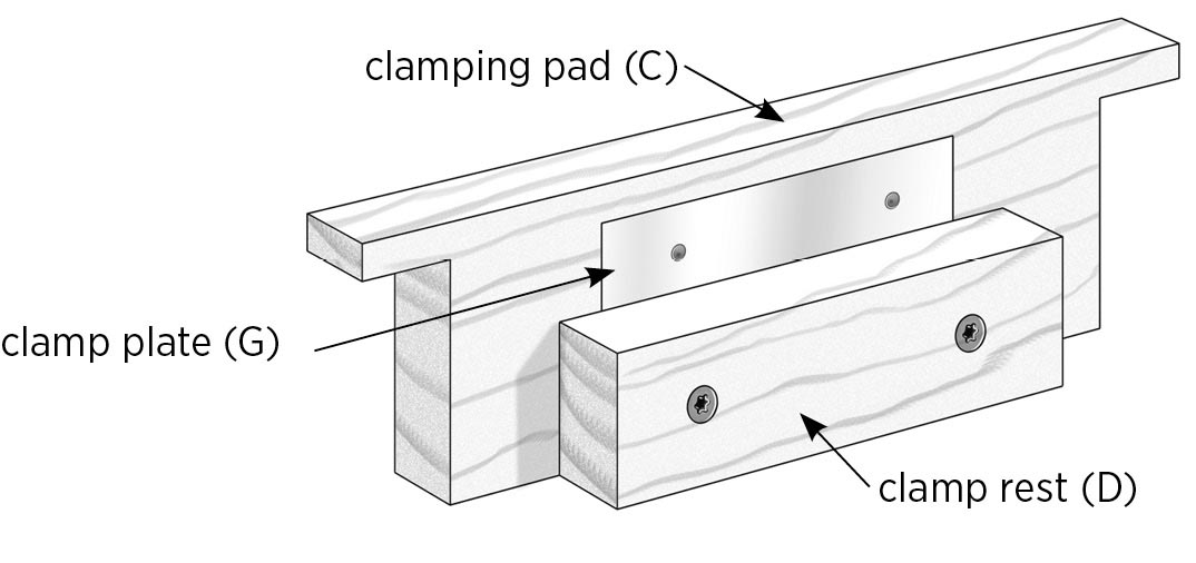
5. Prepare the clamping pads.
You can make the T shape of the clamping pads (C) with one piece, if you have a band saw, or with two pieces, using the table saw. The point is that you should not attempt to notch the ends of these pieces on the table saw.
For the two-piece method, cut a 3⁄8"-wide strip from each part C, and set them aside. Cut the two C pieces to length at 8" and rip them to width at 23⁄8". Glue and nail the 3⁄8" strips back onto the top edge of each C piece so the strips overhang 1" at each end. Use three 4d nails on each strip.
6. Complete the clamping assemblies.
Spread some glue on each clamp rest (D) and place it onto the clamping pad, centered and with the bottom edges flush. Fasten through the rest with two 11⁄4" deck screws (drill pilot holes, if necessary).
Cut two strips of aluminum flashing or other thin metal to size at 7⁄8" × 31⁄2", using tin snips; this is the clamp plate (G), and the size is not fussy. Center a clamp plate over the clamping rest and nail the plate to the clamping pad with a pair of 1⁄2" or 5⁄8" wire nails. The plates will take the pressure of the screw heads on the clamp so they don’t dig into the wood with continued use.
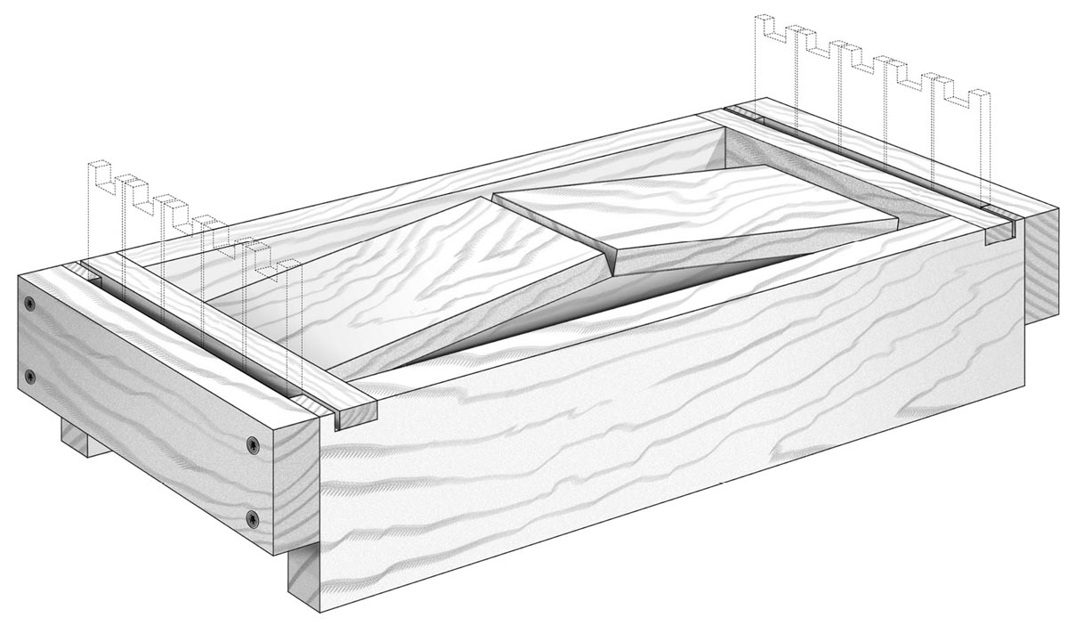
7. Assemble the jig frame.
Set the two side pieces (A) upside down (so the notches are on the bottom) on a flat work surface. Position the end pieces (B), also upside down (frame spacers at the top), aligned with the sides. Clamp the parts together, leaving room to drill holes in the ends. Make sure all ends are flush and the frame is square. Drill countersunk pilot holes about ⅝" and 13⁄4" down from the bottom, and fasten each corner with two 2" deck screws.
Note: Do not glue the ends on. If you need to make any adjustments to the length of your jig, you can always rabbet the edges to make it shorter, or shim it with thin plastic to make it longer.
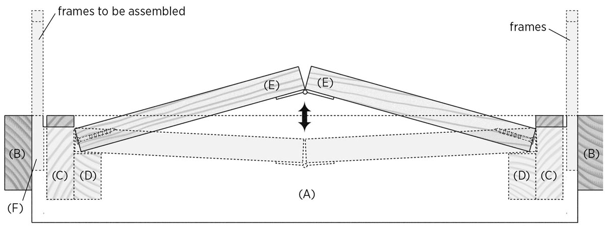
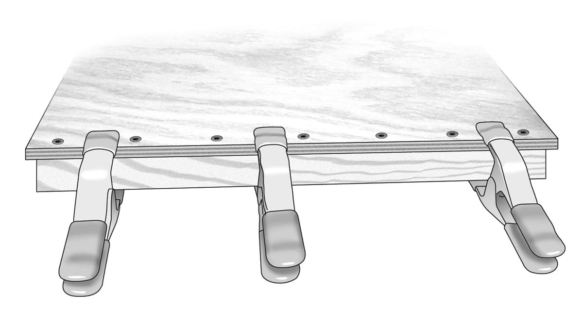
8. Create the clamp.
Drill two countersunk pilot holes into one end of each clamp end (E) as shown in Frame Assembly Jig Parts, on page 92, and drive in two 11⁄4" deck screws so they’re flush. Lay the two pieces end-to-end with the screws at the far ends. Center and fasten the hinge to both pieces to create the clamping mechanism (see Clamping Action with Completed Jig, below).
9. Test the jig.
It’s time to take your frame jig for a test-drive. Position the frame right-side up. Drop the clamping pads into the slots in the sides. Load up the jig with five frame ends on each side. Holding the clamp with the hinge side facing down, bend it slightly to form an angle, like the peak of a roof, and set it down on the clamp rests so it’s square to the frame. Then, press down. Be careful not to have your fingers where they will get pinched. As you press down you will feel pressure, then the clamp should snap into place and hold. If there isn’t enough resistance, back out the screws on the ends of the clamp a little; you can adjust these in and out to make the clamp looser or tighter.
If there’s too much pressure and you can’t push the clamp down all the way, remove the screws on one end of the clamp and trim the board slightly on the table saw. If the clamp snaps down but then pops back up, remove one board from the hinge and trim a little where the two boards meet at the hinge.
When the clamp fits properly, it literally takes a second to secure and release the frames, and you can do it with one hand. (Also see the photo sequence on pages 116–117.)
What Makes a Good Assembly Jig
First of all, it has to be easy to load the side bars into the jig and then hold them in the right position to allow you to glue and nail the top bars on. It also must be able to be turned over so you can glue and nail the bottom bars on. But the real trick to frame assembly jigs is making sure that whatever holds the frames in place on the inside is removable; otherwise, you won’t be able to get the frames out once they’re made. I’ve seen all kinds of methods devised for doing this, from pieces of wood attached to rubber bands to wedges that get hammered in. I found a simple answer sitting right on the desk in my workshop, in the form of a hinged pair of boards salvaged from a folding set of tiered shelves I designed as a craft fair display.
My first prototype looked great on paper and didn’t take very long to build, but it had eight parts to deal with. When I got it finished and did an initial dry run, I put five frame ends in each side. The top bars were easily installed. I thought, “This is nice.” Then, I flipped it over and realized that my clamping setup was in the way of putting the bottom bars on all of the frames. That meant "back to the drawing board." While I was there I noticed a few other issues. My second attempt solved all of those problems and eliminated four parts, and when I did a dry run, it worked great.
The Best-Ever Jig for Installing Foundation
If you are using wooden wedge/grooved or wedge/split frames that you’ve purchased from a bee supply house, installing the sheets of wax foundation can be a little challenging. You have to slide the foundation into the slot on the bottom bar of the frame. The sheets are only somewhat flexible and they don’t always cooperate. On my first hive, I just struggled to put the sheets in by hand. Then I heard about foundation boards: a board with slots cut in it to hold frames at the proper height, allowing the foundation to slide right in.
I made one of these boards and it worked pretty well at first, but if the frame had any twist in it, it was hard to line up the foundation. Also, when I tried using frames from different suppliers, they didn’t fit properly. I tried sticking with frames from one bee supplier, but then they changed the design and those frames didn’t fit. It got kind of frustrating.
Writing this book inspired me to come up with a better way. The jig I designed takes more time and materials to build than the simple foundation board, but I’ve tested it with frames from three different companies and it works with all of them. Another great feature of this jig is that it’s hinged, so once you slide the foundation in place, you can just flip the jig and easily nail in the frame wedge. But what really makes this jig shine is how easily it lets you move the frame and the fact that the thin sheet metal easily aligns with the slot in the frame and guides the wax sheet into it. You will definitely want one of these jigs, so why not make it now? (See photos on pages 118–119.)
Frame Variations
I ordered frames from three different companies — Mann Lake, Brushy Mountain, and Dadant — to see how different they were. The top bars varied in width from 1.006" to 1.087". The width of the bottom bars measured from 0.41" to 0.5". Distances from the edge of the bottom bars to the slots varied from 0.275" to 0.315". The width of the slot was fairly close, varying only 0.01", and averaged 0.17". These variations pose no problems for this jig.
Tools
- Table saw
- Drill and bits:
- Combination drill/countersink bit
- 3⁄16" bit for metal
- Combination square
- Tin snips
Materials
- One 5-foot pine 1×4
- One piece 3⁄8" or 1⁄2" plywood, approximately 12" × 24"
- Scraps of 1⁄4" lauan plywood
- Eighteen 11⁄4" deck screws
- Fifteen 5⁄8" wire nails
- Wood glue
- One piece 26-gauge (0.020" to 0.035" thick) sheet metal, 3" × 16" minimum
- Two 3" hinges with screws
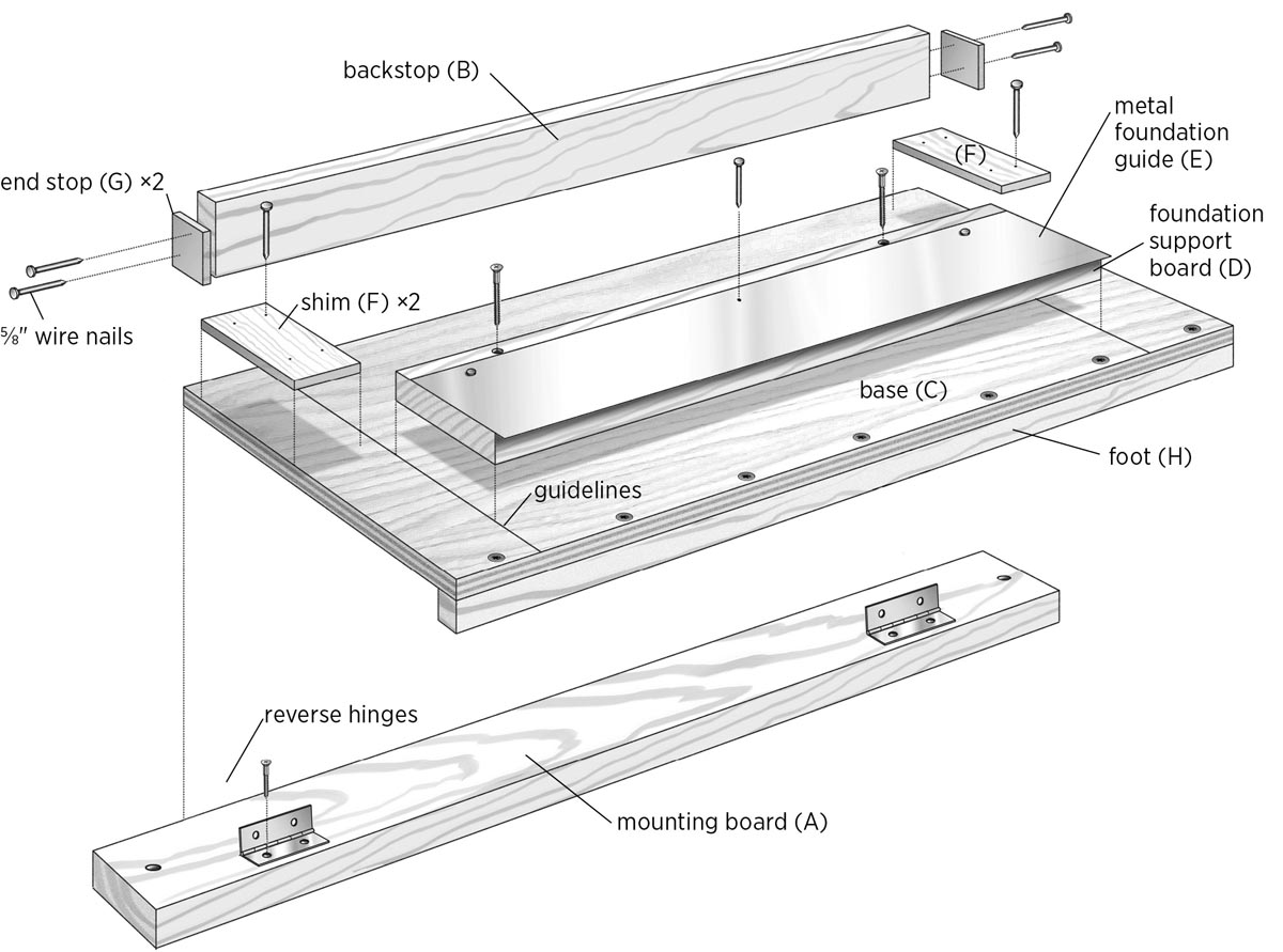
1. Cut the lumber parts.
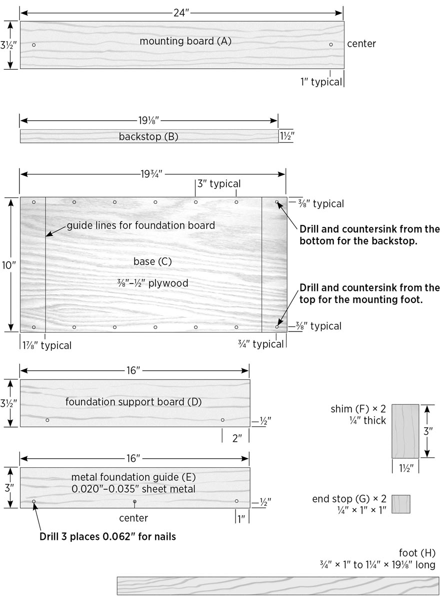
Cut a piece of 1×4 to length at 24" for the mounting board (A). If you plan on screwing your jig to a workbench, drill and countersink a hole for a wood screw, 1" from each end and centered on the board’s width. Alternatively, this board is long enough that you can C-clamp the jig to a bench or table.
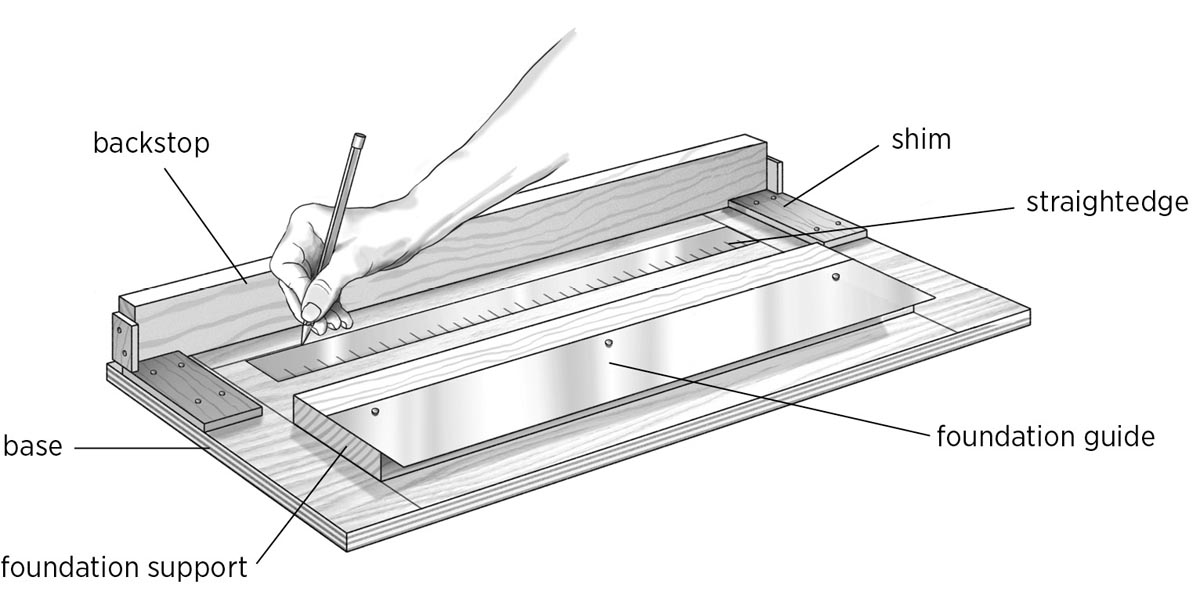
Cut a piece of 1×4 (or wider 1-by scrap) to length at 191⁄8", then rip one strip to width at 11⁄2"; this is the backstop (B). Rip another strip to width at 1" to 11⁄4" wide; this is for the foot (H).
Cut a piece of 1×4 to length at 16" for the foundation support (D). Drill two countersunk pilot holes at 2" from each end and 1⁄2" from one side as shown.
2. Prepare the plywood base.
Cut the plywood base (C) to size at 10" wide × 193⁄4" long. Set a combination square to 17⁄8" and draw a line across each end of the base; these are reference lines for mounting the foundation support board.
Drill pilot holes in the base for the backstop (B) and foot (H), 3⁄4" from the ends and about every 3" in between, as shown in Foundation Board Parts, on facing page. The backstop will be attached to the top face of the base, so you should drill and countersink from the bottom face of the base. The foot will be attached to the bottom face of the base, so drill and countersink from the top face.
3. Mount the backstop.
Set the backstop on-edge on the top face of the plywood base, aligning it flush with the bottom edge of the base and centering it lengthwise; there should be about 5⁄16" between each end of the backstop and the side edge of the base. Clamp the backstop in place, then flip over the base and drive 11⁄4" deck screws into your predrilled pilot holes, working from the bottom side of the base.
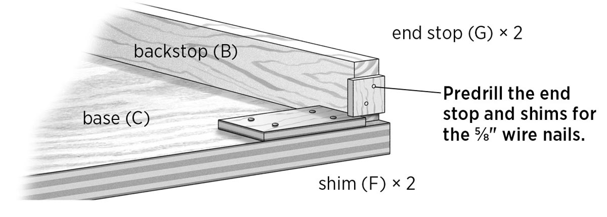
4. Cut and install the shims and end stops.
Cut two shims (F) to size at 11⁄2" × 3", using scraps of 1⁄4" lauan plywood. Spread some glue on the shims and attach one to each end of the base, using 5⁄8" wire nails. Butt the 11⁄2" edge of the shim against the backstop, with the 3" edge flush with the side edge of the base.
Cut two end stops (G) at 1" × 1", using 1⁄4" lauan plywood. Attach the end stops to the ends of the backstop with glue and 5⁄8" wire nails.
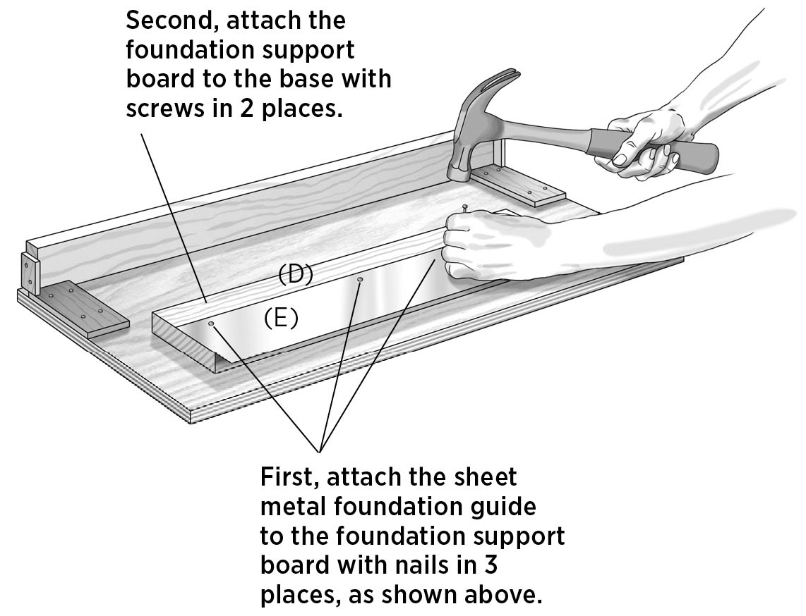
5. Mount the foundation guide.
Cut the foundation guide (E) to size at 3" × 16" from 26-gauge sheet metal. You can find galvanized steel sheet metal at home centers, hardware stores, metalworking shops, and vocational schools (where you might be able to get a scrap for free, as well as have the piece cut for you.) You can also use copper, which you can probably nail right through without drilling pilot holes.
Drill pilot holes for nails using a 1⁄16" bit; locate these 1⁄2" from one long edge side, spacing them 1", 8", and 15" from one end. Set the guide on the foundation support board (D) so that the ends are flush and the metal guide overhangs the front edge (opposite the pilot holes you drilled in step 1) of the support board by 1⁄2". Fasten the guide with 5⁄8" wire nails.
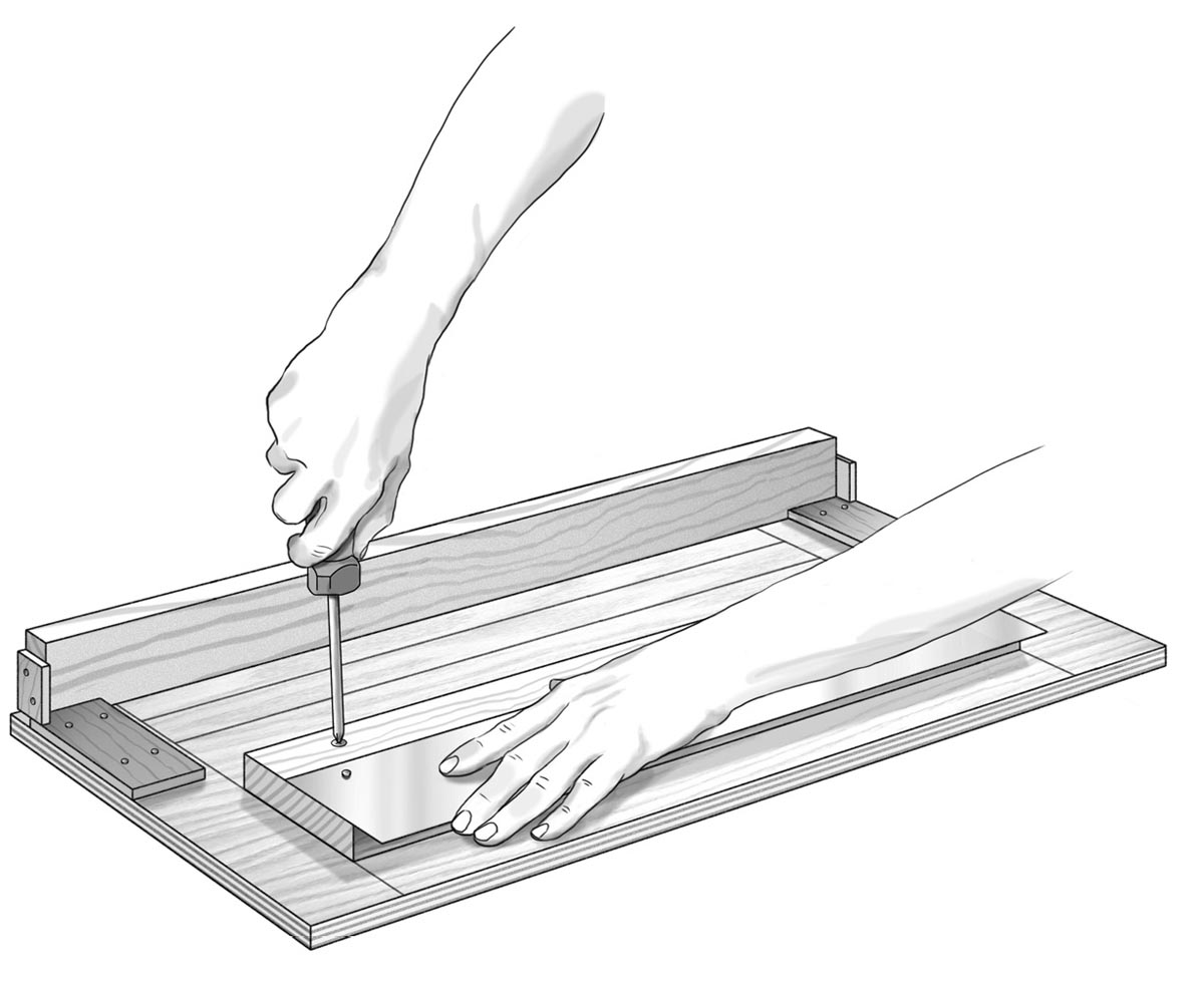
6. Make the foundation support holes.
In this step you will mark and create holes for the foundation support board (with metal guide attached) to accommodate three different frame depths. First, place a deep frame on the base, with the top bar of the frame clamped against the backstop. Place the foundation support on the inside of the frame so the metal guide bottoms out in the groove of the deep frame. Hold the guide in place, then carefully remove the frame. Measure the distance between the backstop and the foundation support board, subtract 1⁄8", and write down this figure. Repeat this process with medium and shallow frames, being sure to subtract 1⁄8" from your measurements.
Mark and draw lines at each of your three noted distances from the backstop. Position the foundation support board at each line so both ends are on the 17⁄8" reference lines you made in step 2. Using the combination drill/countersink bit placed in the mounting holes in the support board, drill into the plywood base to mark the positions. Enlarge the holes in the support board only (not the base) using the 3⁄16" drill bit, then screw the support board in at each of the three locations.
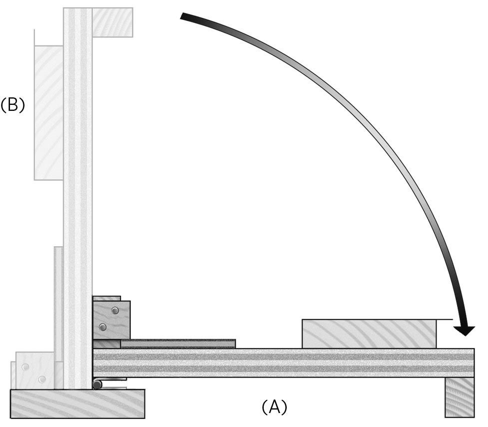
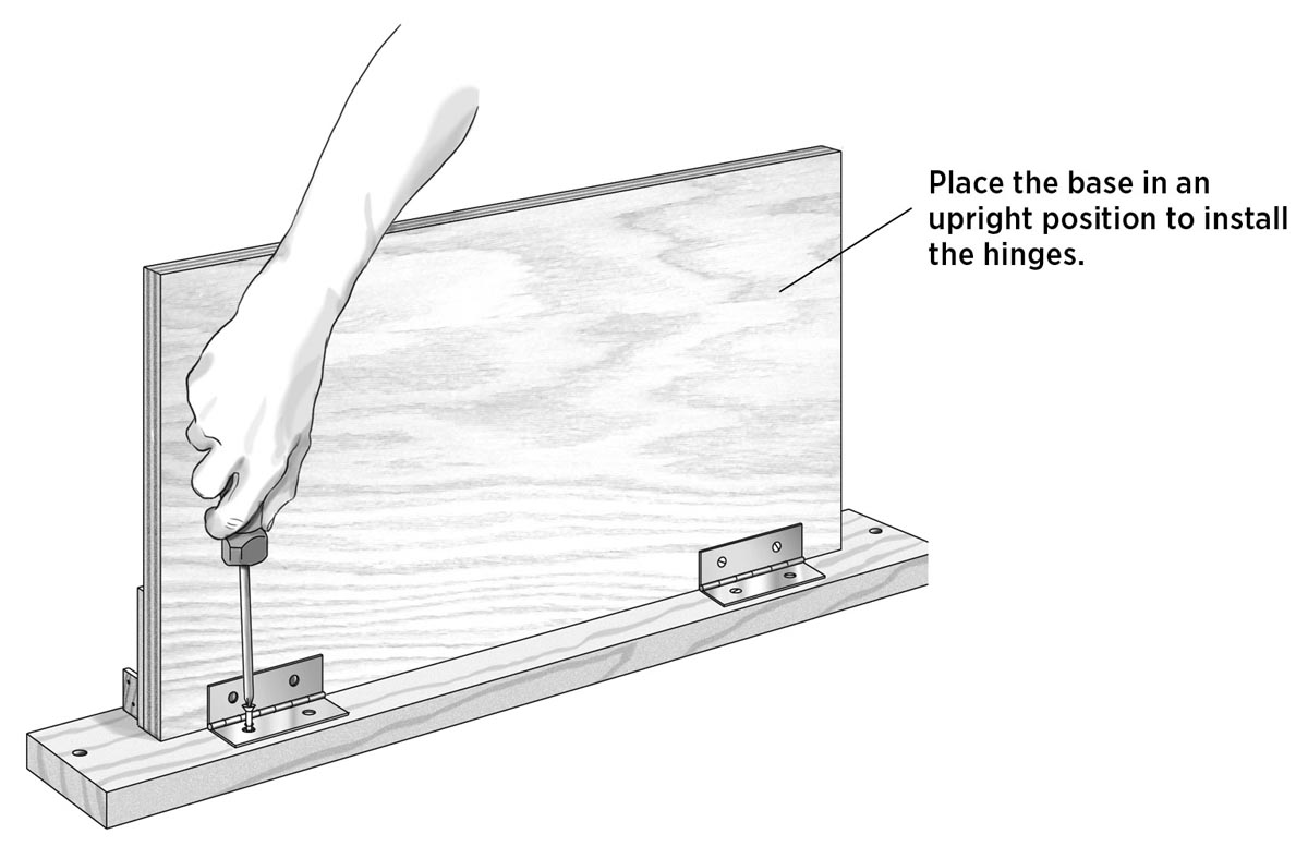
7. Add the mounting board.
Stand up the jig assembly and position it so the backstop is resting on the mounting board and the bottom of the plywood base is facing you. The top of the backstop should be flush with the far edge of the mounting board. Position a hinge 1" from each side edge of the base, and mark the holes for the hinge mounting screws. Fasten the hinges to the base and mounting board with the provided screws.
8. Install the foot.
Attach the foot to the bottom of the plywood base (opposite the backstop), using 11⁄4" screws driven through the predrilled holes in the front face of the base. The foot should be flush with the long edge of the base.
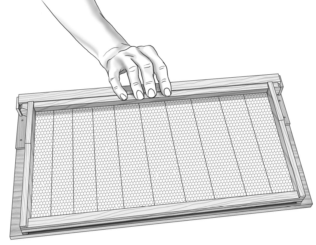
9. Try it out.
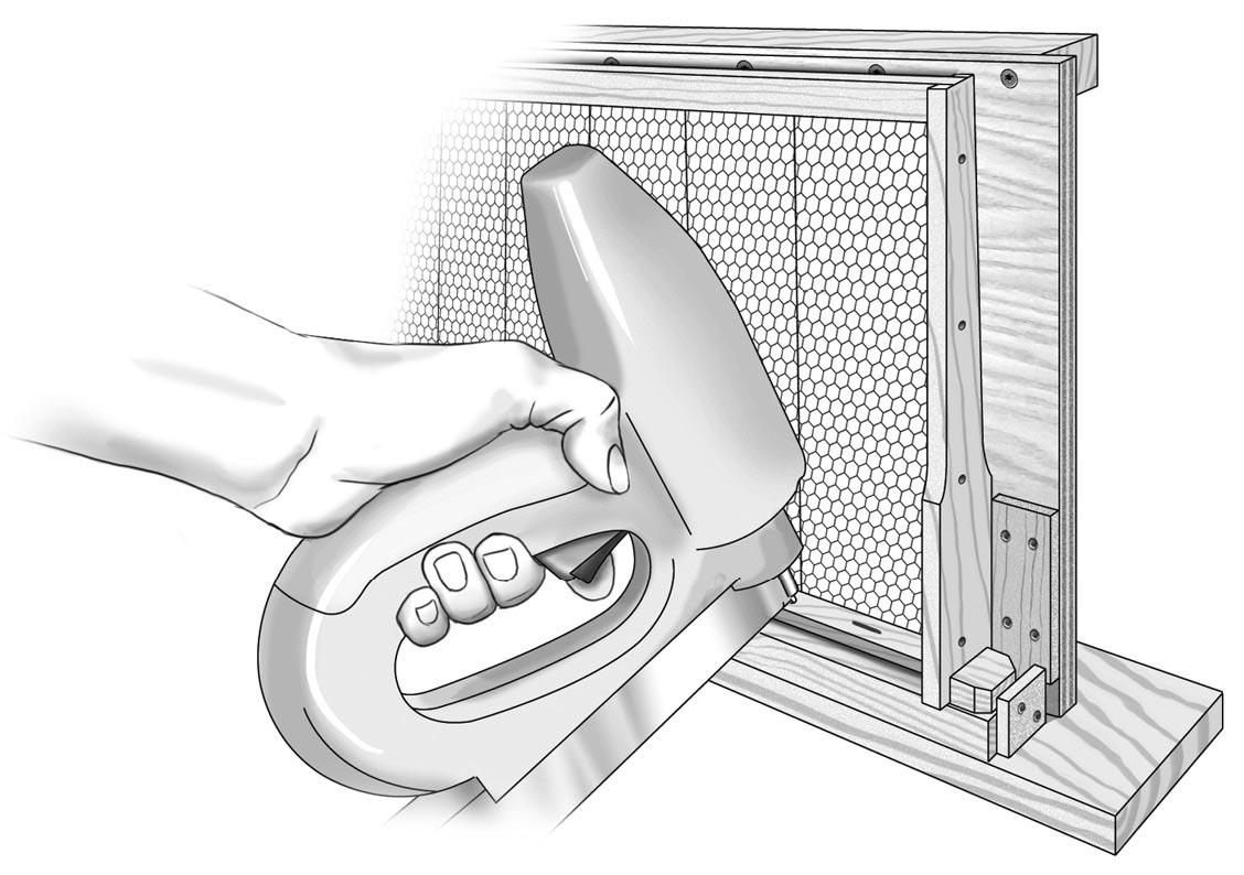
Set a frame on the jig and slide the top bar toward the backstop as you direct the metal foundation guide into the frame’s groove (this is easy because the frame is free to move up and down slightly). With the top bar fully against the backstop, push down slightly to raise the other end, creating a gap between the metal guide and the top edge of the groove; this makes it super-easy to slide the foundation into the groove.
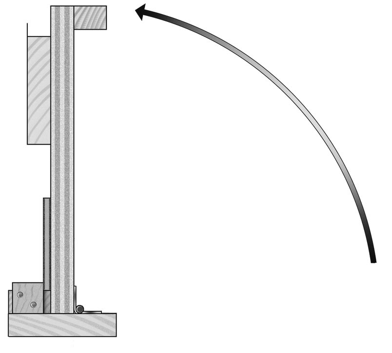
Install the foundation, then simply pivot the jig into vertical position, nail your wedge into place, lift the frame off the jig, and you’re ready for the next one. It couldn’t be easier. (Also see photo sequence on pages 118–119.)