CHAPTER 4
EAL Unit QELTK3/006
Understanding the principles, practices and legislation for the inspection, testing, commissioning and certification of electrotechnical systems

Learning outcomes
When you have completed this chapter you should:
1. Understand the principles, regulatory requirements and procedures for completing the safe isolation of an electrical circuit and complete electrical installations in preparation for inspection, testing and commissioning.
2. Understand the principles and regulatory requirements for inspecting, testing and commissioning electrical systems, equipment and components.
3. Understand the regulatory requirements and procedures for completing the inspection of electrical installations.
4. Understand the regulatory requirements and procedures for the safe testing and commissioning of electrical installations.
5. Understand the procedures and requirements for the completion of electrical installation certificates and related documentation.
Assessment criteria 1.1
State the requirements of the Electricity at Work Regulations 1989 for the safe inspection of electrical systems and equipment, in terms of those carrying out the work and those using the building during the inspection
The Electricity at Work Regulations 1989 (EWR)
This legislation came into force in 1990 and is made under the Health and Safety at Work Act 1974, and enforced by the Health and Safety Executive. The purpose of the regulations is to ‘require precautions to be taken against the risk of death or personal injury from electricity in work activities’. This regulation gives a clear statement of who the EWR applies to and makes a statement:
It shall be the duty of every employee while at work to comply with the provisions of these regulations in so far as they relate to matters which are within his/her control.
This means that a trainee electrician, although not fully qualified, must adhere to the EWR as well as always cooperating with their employer. The EWR also applies to non-technical personnel such as an office worker for instance, who must realize what they can or cannot do regarding electrical equipment and the importance of not interfering with safety equipment.
 Safety first
The EWR expects all electricians to work on dead supplies unless it is unreasonable for them not to be live. In other words all supplies must be dead unless it can be justified why they remain live.
Regulation 13 Precautions for work on equipment made dead
This regulation ensures that adequate precautions shall be taken to prevent electrical equipment which has been made dead from becoming live when work is carried out on or near that equipment. In essence, what this regulation is proposing is that electricians always carry out a safe isolation procedure. The regulation also states that where reasonable a written procedure known as a permit to work is used to authorize and control electrical maintenance.
Regulation 14 Work on or near live conductors
This regulation ensures that no person shall be engaged in any work activity on or so near any live conductor (other than one suitably covered with insulating material so as to prevent danger) that danger may arise unless:
(a) it is unreasonable in all the circumstances for it to be dead; and
(b) it is reasonable in all the circumstances for him to be at work on or near it while it is live; and
(c) suitable precautions (including where necessary the provision of suitable protective equipment) are taken to prevent injury.
In other words, there is an expectation that electricians only work on dead supplies unless there is a reason against it and you can justify that reason. The regulation also specifies that the test instrument used to establish that a circuit is dead has to be fit for purpose or ‘approved’ as laid out through GS38 specifically written by the Health and Safety Executive.
Safety first
Isolation
• Never work ‘live’.
• Isolate.
• Secure the isolation.
• Prove the work supply ‘dead’ before starting work.
Assessment criteria 1.2
Specify and undertake the correct procedure for completing safe isolation with regard to carrying out safe working practices etc.
Secure electrical isolation
Electric shock occurs when a person becomes part of the electrical circuit. The level or intensity of the shock will depend upon many factors, such as age, fitness and the circumstances in which the shock is received. The lethal level is approximately 50 mA, above which muscles contract, the heart flutters and breathing stops. A shock above the 50 mA level is therefore fatal unless the person is quickly separated from the supply. Below 50 mA only an unpleasant tingling sensation may be experienced or you may be thrown across a room or shocked enough to fall from a roof or ladder, but the resulting fall may lead to serious injury.
To prevent people from receiving an electric shock accidentally, all circuits contain protective devices. All exposed metal is earthed; fuses and circuit-breakers (CBs) are designed to trip under fault conditions, and residual current devices (RCDs) are designed to trip below the fatal level as described in Chapter 3, page 189.

Figure 4.1 Electric shock occurs when a person becomes part of a live circuit.
Construction workers and particularly electricians do receive electric shocks, usually as a result of carelessness or unforeseen circumstances. As an electrician working on electrical equipment you must always make sure that the equipment is switched off or electrically isolated before commencing work. Every circuit must be provided with a means of isolation (IET Regulation 132.15). When working on portable equipment or desk top units it is often simply a matter of unplugging the equipment from the adjacent supply. Larger pieces of equipment and electrical machines may require isolating at the local isolator switch before work commences. To deter anyone from re-connecting the supply while work is being carried out on equipment, a sign ‘Danger – Electrician at Work’ should be displayed on the isolator and the isolation ‘secured’ with a small padlock or the fuses removed so that no one can re-connect while work is being carried out on that piece of equipment. The Electricity at Work Regulations 1989 are very specific at Regulation 12(1) that we must ensure the disconnection and separation of electrical equipment from every source of supply and that this disconnection and separation is secure. Where a test instrument or voltage indicator is used to prove the supply is dead, Regulation 4(3) of the Electricity at Work Regulations 1989 recommends that the following procedure is adopted.
 Definition
Electrical isolation – we must ensure the disconnection and separation of electrical equipment from every source of supply and that this disconnection and separation is secure.
1 First, connect the test device such as that shown in Fig. 4.2 to the supply, which is to be isolated. The test device should indicate mains voltage.
2 Next, isolate the supply and observe that the test device now reads zero volts.
3 Then connect the same test device to a known live supply or proving unit such as that shown in Fig. 4.4 to ‘prove’ that the tester is still working correctly.
4 Finally, secure the isolation and place warning signs; only then should work commence.
Definition
GS38 is a method statement specifcally written by the HSE detailing approved equipment and exacting processes required when undertaking safe isolation procedures.
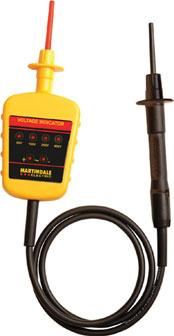
Figure 4.2 Typical voltage indicator.
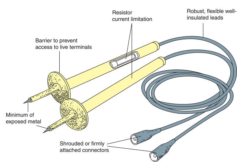
Figure 4.3 Recommended type of test probe and leads.

Figure 4.4 Modern proving unit.
The test device being used by the electrician must incorporate safe test leads that comply with the Health and Safety Executive Guidance Note 38 (fourth edition, 2015) on electrical test equipment. These leads should incorporate barriers to prevent the user from touching live terminals when testing, but most testers do not include a protective fuse because they can add significant resistance to the test leads. While protection is still afforded through electronic circuitry, the meter leads should be well insulated and robust, such as those shown in Figure 4.3 with exposed metal tips optimally extending by 2mm but never more than 4mm in length. To isolate a piece of equipment or individual circuit successfully, competently, safely and in accordance with all the relevant regulations, we must follow a procedure such as that given by the flow diagram of Fig. 4.6. Start at the top and work down the flow diagram.
When the heavy outlined amber boxes are reached, pause and ask yourself whether everything is satisfactory up until this point. If the answer is ‘yes’, move on. If the answer is ‘no’, go back as indicated by the diagram.
Safety first
Your first objective when carrying out safe isolation procedures is to carry out a risk assessment of your working area.
Live testing
The Electricity at Work Regulations 1989 at Regulation 4(3) tell us that it is preferable that supplies be made dead before work commences. However, it does acknowledge that some work, such as fault finding and testing, may require the electrical equipment to remain energized. Therefore, if the fault finding and testing can only be successfully carried out live, then the person carrying out the fault diagnosis must:
Safety first
An inherent danger of applying testing procedures is that electricians have to periodically work on live supplies.
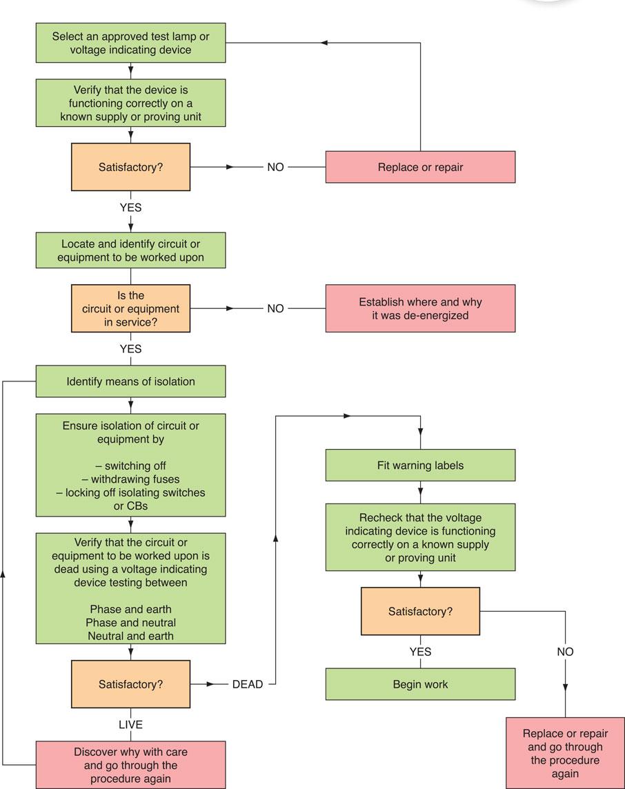
Figure 4.5 Flowchart for secure isolation procedure.
• be trained so that they understand the equipment and the potential hazards of working live and can, therefore, be deemed ‘competent’ to carry out that activity;
• only use approved test equipment;
• set up appropriate warning notices and barriers so that the work activity does not create a situation dangerous to others.
While live testing may be required by workers in the electrical industries in order to find a fault, live repair work must not be carried out. The individual circuit or piece of equipment must first be isolated before work commences in order to comply with the Electricity at Work Regulations 1989.
Assessment criteria 1.3
State the implications of carrying out safe isolations
Assessment criteria 1.4
State the implications of not carrying out safe isolations
Assessment criteria 1.5
Identify all health and safety requirements that apply when inspecting, testing and commissioning electrical installations and circuits
Safe working procedures – inspection and testing
Whether you are carrying out the inspection and test procedure (i) as a part of a new installation, (ii) upon the completion of an extension to an existing installation, (iii) because you are trying to discover the cause of a fault on an installation or (iv) because you are carrying out an electrical installation condition report of a building, you must always be aware of your safety, the safety of others using the building and the possible damage that your testing might cause to other systems in the building.
For your own safety:
• Always use ‘approved’ test instruments and probes.
• Ensure that the test instrument carries a valid calibration certificate, otherwise the results may be invalid.
• Secure all isolation devices in the ‘off’ position.
• Put up warning notices so that other workers will know what is happening.
• Notify everyone in the building that testing is about to start and for approximately how long it will continue.
• Obtain a ‘permit to work’ if this is relevant.
• Obtain approval to have systems shut down that might be damaged by your testing activities. For example, computer systems may ‘crash’ when supplies are switched off. Ventilation and fume extraction systems will stop working when you disconnect the supplies.
Safety first
A breakdown in communication either through a failure of procedures such as permits, or messages not being recorded or passed on could not only affect production but endanger life.
For the safety of other people:
• Fix warning notices around your work area.
• Use cones and highly visible warning tape to screen off your work area.
• Make an effort to let everyone in the building know that testing is about to begin. You might be able to do this while you carry out the initial inspection of the installation.
• Obtain verbal or written authorization to shut down information technology, emergency operation or standby circuits.
To safeguard other systems:
• Computer systems can be severely damaged by a loss of supply or the injection of a high test voltage from, for example, an insulation resistance test. Computer systems would normally be disconnected during the test period but this will generally require some organization before the testing begins. Commercial organizations may be unable to continue to work without their computer systems and, in these circumstances, it may be necessary to test outside the normal working day.
• Any resistance measurements made on electronic equipment or electronic circuits must be achieved with a battery-operated ohmmeter in order to avoid damaging the electronic circuits.
• Farm animals are creatures of habit and may become very grumpy to find you testing their milking parlour equipment at milking time.
Hospitals and factories may have emergency standby generators that reenergize essential circuits in the event of a mains failure. Your isolation of the circuit for testing may cause the emergency systems to operate. Discuss any special systems with the person authorizing the work before testing begins.
Assessment criteria 2.1
State the purpose of and requirements for initial verification and periodic inspection of electrical installations
Assessment criteria 2.2
Identify and interpret the requirements of the relevant documents associated with the inspection, testing and commissioning of an electrical installation
Why inspect and test an electrical installation?
The purpose of carrying out an initial verification of a new building is to ensure that the installation complies with the design, and construction aspects of BS 7671 that are reasonably practicable (GN3, Chapter 2). In doing so the inspection and testing of an electrical installation will:
1 ensure the safety of people and livestock;
2 ensure the protection of property from fire and heat;
3 confirm that the property has not been damaged or deteriorated so as to reduce its safety;
4 identify any defects in the installation and the subsequent need for improvement.
All electrical equipment deteriorates with age as well as with wear and tear from being used. It also deteriorates as a result of excessive loading and environmental influences leading to, for example, corrosion. The electrical installation must therefore be inspected and tested periodically during its lifetime to confirm that it remains safe to use at least until the next inspection and test is carried out. Organizations insuring buildings often require evidence that the electrical installation is safe and that the insurer’s risk is therefore low. For example, insurance companies and mortgage lenders ask for electrical inspection and test reports when:
• there has been a change of building occupancy;
• there is a change of use of the building;
• alterations have been carried out;
• there is reason to believe that damage may have been caused to the building as a result of, for example, flooding.
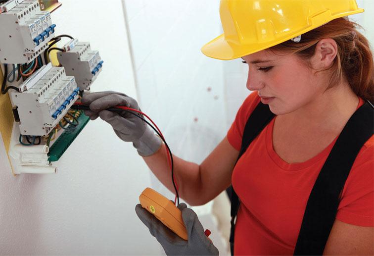
Figure 4.6 Like most things electrical equipment deteriorates with age, so it is important to have it periodically tested during its lifetime.
In the event of an injury or fire alleged to have been caused by the electrical installation itself, the production of past certificates and reports will provide documentary evidence that the installation has been installed and subsequently maintained to a satisfactory standard of safety by skilled or instructed persons. Statutory and non-statutory regulations also clearly state the requirements for inspection and testing as a part of a maintenance programme to reduce danger. Regulation 4 (2) of the Electricity at Work Regulations advises that ‘as may be necessary to prevent danger, all systems shall be maintained so as to prevent such danger’.
The Guidance Notes on the Electricity at Work Regulations advise that this regulation is concerned with the need for maintenance to ensure the safety of ‘the system’ and not the actual ‘doing of maintenance’ in a safe manner. The regular inspection of equipment including the electrical installation is an essential part of any preventative maintenance programme.
There is no specific requirement to test the installation on every inspection. Where testing requires dismantling, the tester should consider whether the risks associated with dismantling and reassembly are justified. Dismantling, and particularly disconnection of cables and components, introduces the possible risk of unsatisfactory reassembly.
IET Regulations 641 advise us that every installation shall, during erection and on completion before being put into service, be inspected and tested to verify that the regulations have been met. Regulation 651 also advises that where required, periodic inspection and testing shall be carried out in order to determine if the installation is in a satisfactory condition for continued service. Regulation 642.3 gives us an inspection checklist and tells us that the inspection must include at least these 20 or more items plus, if appropriate, the particular requirements for special installations such as bathrooms described in Part 7 of the regulations. The On-Site Guide at Section 9.2.2 gives the same inspection checklist. Guidance Note 3 gives us guidance in using the IET checklist given in Regulation 642.3. We will look at this checklist later in this chapter under the sub-heading ‘Visual inspection’.
The Electrician’s Guide to the Building Regulations Part P at Section 6.2 follows the requirements given in Section 641 of the IET Regulations. Appendix 6 of the IET Regulations gives us a Condition Report Inspection Schedule (schedule means a planned programme of work) for a domestic or similar premises with an up to 100 A supply. This inspection schedule checklist is to be used when carrying out a periodic inspection of an existing installation for the purpose of completing an Electrical Installation Condition Report (see page 476 of Blue 18th Edition).
Assessment criteria 2.3
Specify the information that is required to correctly conduct the initial verification of an electrical installation in accordance with the IET Wiring Regulations and IET Guidance Note 3
Both the IET Wiring Regulations and IET Guidance Note 3 specify that certain information must be made available to the inspector when carrying out initial verification. First, any relevant diagrams, charts or tables that contain information such as utilization points, type and composition of circuits and how such elements as fault and basic protection are provided. Furthermore, details should be provided of the general characteristics such as:
• maximum demand;
• number and type of conductors;
• earthing system used;
• nominal voltage;
• supply frequency and current;
• prospective short circuit current at the origin;
• Ze (suppliers earth loop impedance value);
• type and rating of overcurrent protection devices.
Assessment criteria 3.1
Identify the items to be checked during the inspection process for given electrotechnical systems and equipment, and their locations as detailed in the IET Wiring Regulations
Assessment criteria 3.3
State the items of an electrical installation that should be inspected in accordance with IET Guidance Note 3
Sampling when carrying out inspections
The inspection required of an electrical installation must be a ‘detailed examination’ of the installation without dismantling or with only partial dismantling as is required (IET Regulation 651.2). A thorough visual inspection should be made of all electrical equipment that is not concealed and should include the accessible internal condition of a sample of the electrical equipment. It is not practicable to inspect every joint and termination in an electrical installation. Nevertheless, a detailed examination of the installation, without dismantling, should be made of all switches, switchgear, distribution boards, luminaire points and socket outlets to ensure that all terminal connections of the conductors are properly installed and secure. Any signs of overheating of conductors, terminations or equipment should be thoroughly investigated and included in the report (Guidance Note 3 section 3.8).
Considerable care and engineering judgement must be exercised when deciding upon the extent of the sample to receive the ‘covers removed’ visual inspection. The factors to be considered when determining the size of the sample are:

Figure 4.7 Past certificates may not always be available, but you should always complete the appropriate paperwork when testing installations.
• the availability of previous certificates;
• the age and condition of the installation;
• any evidence of ongoing maintenance;
• the time elapsed since the previous inspection;
• the size of the installation.
If no previous certificates are available and the installation is looking tired or abused it would be necessary to inspect and test a larger percentage of the installation and in some cases 100% of the installation. The degree or extent of the sampling must be agreed with the person ordering the work before work commences. It may be impractical to inspect and test the whole of a large installation at one time. If this is the case and sampling is agreed with the person ordering the work, it is important to examine different parts of the installation in subsequent inspections. It would not be acceptable for the same parts of the installation to be repeatedly inspected to the exclusion of other parts.
Assessment criteria 3.2
State how human senses (sight, touch etc.) can be used during the inspection process
The senses of sight, hearing, smell and touch are powerful human forces that we can use when carrying out the ‘covers removed’ electrical inspection or when we are attempting to trace a fault on a circuit. Connections can become hot under fault conditions, which may be as a result of loose connections or a circuit overload. The heat generated by the electrical fault might heat up the insulation of the conductors and the terminal block holding the connections. In these circumstances, the Bakelite insulation used in the construction of terminal blocks and switchgear becomes hot and gives off a pungent smell, like rotting fish. So, we can use our powerful human sense of smell to guide us to the source of possible faults. Conductor insulation blackens when it becomes very hot and becomes brittle and stiff. Once more, we can use the human senses of sight and touch to detect these faults when carrying out an internal inspection of socket outlets, switches and luminaries.
Assessment criteria 3.4
Specify the requirements for inspection
Visual inspection
The installation must be visually inspected before testing begins. The aim of the visual inspection is to confirm that all equipment and accessories are undamaged and comply with the relevant British and European Standards, and also that the installation has been securely and correctly erected. IET Regulation 642.3 gives a checklist or schedule for the initial visual inspection of an installation, including:
• connection of conductors;
• identification of conductors;
• routeing of cables in safe zones;
• selection of conductors for current-carrying capacity and volt drop;
• connection of single-pole devices for protection or switching in phase conductors only;
• correct connection of socket outlets, lampholders, accessories and equipment;
• presence of fire barriers, suitable seals and protection against thermal effects;
• methods of ‘basic protection’ against electric shock, including the insulation of live parts and placement of live parts out of reach by fitting appropriate barriers and enclosures;
• methods of ‘fault protection’ against electric shock, including the presence of earthing conductors for both protective bonding and supplementary bonding;
• prevention of detrimental influences (e.g. corrosion);
• presence of appropriate devices for isolation and switching;
• presence of undervoltage protection devices;
• choice and setting of protective devices;
• labelling of circuits, fuses, switches and terminals;
• selection of equipment and protective measures appropriate to external influences;
• adequate access to switchgear and equipment;
• presence of danger notices and other warning notices;
• presence of diagrams, instructions and similar information;
• appropriate erection method.
The checklist is a guide. It is not exhaustive or detailed, and should be used to identify relevant items for inspection, which can then be expanded upon. For example, the first item on the checklist, connection of conductors, might be further expanded to include the following:
• Are connections secure?
• Are connections correct? (conductor identification)
• Is the cable adequately supported so that no strain is placed on the connections?
• Does the outer sheath enter the accessory?
• Is the insulation undamaged?
• Does the insulation proceed up to, but not into, the connection?
This is repeated for each appropriate item on the checklist.
Assessment criteria 4.1
State the tests to be carried out on an electrical installation in accordance with the IET Wiring Regulations and IET Guidance Note 3
Assessment criteria 4.4
Explain why it is necessary for test results to comply with standard values and state the actions to take in the event of unsatisfactory results being obtained
Assessment criteria 4.5
Explain why testing is carried out in the exact order as specified in the IET Wiring Regulations and IET Guidance Note 3
Electrical testing
The electrical contractor is charged with a responsibility to carry out a number of tests on an electrical installation and electrical equipment. The individual tests are dealt with in Part 6 of the IET Regulations and Chapter 2 of GN3, described later in this chapter.
The reasons for testing the installation are:
• to ensure that the installation complies with the IET Regulations;
• to ensure that the installation meets the specification;
• to ensure that the installation is safe to use.
Those who are to carry out the electrical tests must first consider the following safety factors:
• an assessment of safe working practice must be made before testing begins;
• all safety precautions must be put in place before testing begins;
• everyone must be notified that the test process is about to take place, for example the client and other workers who may be affected by the tests;
• ‘permits to work’ must be obtained where relevant;
• all sources of information relevant to the tests have been obtained;
• the relevant circuits and equipment have been identified;
• safe isolation procedures have been carried out – care must be exercised here, in occupied premises, not to switch off computer systems without first obtaining permission;
• those who are to carry out the tests are competent to do so.
Chapter 2 of GN3 states that initial tests should be carried out in the following sequence where relevant and practical. The tests are devised so that safety critical elements such as continuity of protective conductors and insulation resistance are carried out whilst the circuit is made dead, before live testing of the installation takes place. The test is listed as follows:
(a) Test for continuity of protective conductors, including protective equipotential and supplementary bonding
(b) Test the continuity of all ring final circuit conductors
(c) Test for insulation resistance
(d) Protection by SELV, PELV, or by electrical separation
(e) Protection by barriers or enclosures
(f) Insulation resistance of non-conducting locations
(g) Polarity
(h) Earth electrode resistance
(i) Protection by automatic disconnection of the supply
(j) Test the earth fault loop impedance
(k) Additional protection
(l) Prospective fault current
(m) Check of phase sequence
(n) Functional testing
(o) Verification of volt drop
If any test fails to comply with the IET Regulations, then all the preceding tests must be repeated after the fault has been rectified. This is because the earlier test results may have been influenced by the fault (IET Regulation 643.1). There is an increased use of electronic devices in electrical installation work; for example, in dimmer switches and ignitor circuits of discharge lamps. These devices should temporarily be disconnected so that they are not damaged by the test voltage of, for example, the insulation resistance test (IET Regulation 643.3).
Assessment criteria 4.2
Identify the correct instrument for the test to be carried out
The electrical contractor is required by the IET Regulations to test all new installations and major extensions during erection and upon completion before being put into service. The contractor may also be called upon to test installations and equipment in order to identify and remove faults.
These requirements imply the use of appropriate test instruments, and in order to take accurate readings consideration should be given to the following points:
• Is the instrument suitable for this test?
• Has the correct scale been selected?
• Is the test instrument correctly connected to the circuit?
Many commercial instruments are capable of making more than one test or have a range of scales to choose from. A range selector switch is usually used to choose the appropriate scale. A scale range should be chosen that suits the range of the current, voltage or resistance being measured. For example, when taking a reading in the 8 or 9 V range, the obvious scale choice would be one giving 10 V full-scale deflection. To make this reading on an instrument with 100 V full-scale deflection would lead to errors, because the deflection is too small. Ammeters must be connected in series with the load, and voltmeters in parallel across the load as shown in Fig. 4.8. The power in a resistive load may be calculated from the readings of voltage and current since P = VI. This will give accurate calculations on both a.c. and d.c. supplies, but when measuring the power of an a.c. circuit that contains inductance or capacitance, a watt meter must be used because the voltage and current will be out of phase.
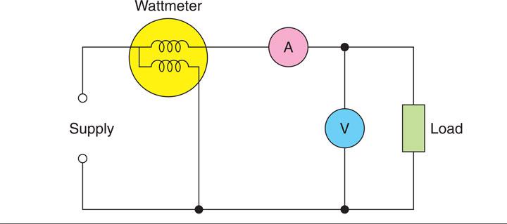
Figure 4.8 Wattmeter, ammeter and voltmeter correctly connected to a load.
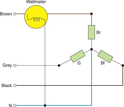
Figure 4.9 One-wattmeter measurement of power.
Measurement of power in a three-phase circuit
One-wattmeter method
When three-phase loads are balanced, for example, in motor circuits, one wattmeter may be connected into any phase, as shown in Fig. 4.9. This wattmeter will indicate the power in that phase and, since the load is balanced, the total power in the three-phase circuit will be given by:
Two-wattmeter method
This is the most commonly used method for measuring power in a three-phase, three-wire system since it can be used for both balanced and unbalanced loads connected in either star or delta. The current coils are connected to any two of the lines, and the voltage coils are connected to the other line, the one without a current coil connection, as shown in Fig. 4.10. Then,
This equation is true for any three-phase load, balanced or unbalanced, star or delta connection, provided there is no fourth wire in the system.
Three-wattmeter method
If the installation is four-wire, and the load on each phase is unbalanced, then three-wattmeter readings are necessary, connected as shown in Fig. 4.11.
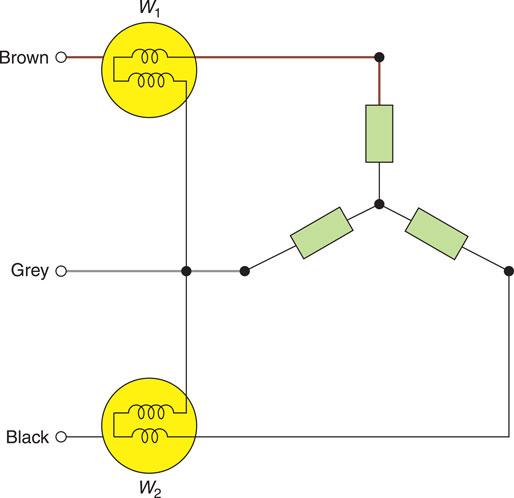
Figure 4.10 Two-wattmeter measurement of power.
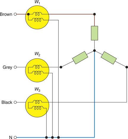
Figure 4.11 Three-wattmeter measurement of power.
Each wattmeter measures the power in one phase and the total power will be given by:
Tong tester
The tong tester, or clip-on ammeter, offers an easy method of measuring current without any connections being made. It works on the same principle as the transformer. The laminated core of the transformer can be opened and passed over the busbar or single-core cable. In this way a measurement of the current being carried can be made without disconnection of the supply. The construction is shown in Fig. 4.12.

Figure 4.12 Tong tester or clip-on ammeter.
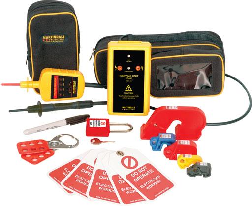
Figure 4.13 Some of the electrical testing essentials: lock-offs, warning signs, padlock with key and a proving unit.
Assessment criteria 4.3
Specify the requirements for the safe and correct use of instruments to be used for testing and commissioning
Approved test instruments
The test instruments and test leads used by the electrician for testing an electrical installation must meet all the requirements of the relevant regulations.
The HSE has published guidance note GS 38 for test equipment used by electricians. The IET Regulations (BS 7671) and GN3 also specify the test voltage or current required to carry out particular tests satisfactorily. All test equipment must be chosen to comply with the relevant parts of BS EN 61557.
Definition
The test instruments and test leads used by the electricians for testing an electrical installation must meet all the requirements of the relevant regulations.
All testing must, therefore, be carried out using an ‘approved’ test instrument if the test results are to be valid. The test instrument must also carry a calibration certifícate, otherwise the recorded results may be void. Calibration certificates usually last for a year. Test instruments must, therefore, be tested and recalibrated each year by an approved supplier. This will maintain the accuracy of the instrument to an acceptable level, usually within 2% of the true value. Modern digital test instruments are reasonably robust, but to maintain them in good working order they must be treated with care. An approved test instrument costs as much as a good quality camera; it should, therefore, receive the same care and consideration. It therefore should go without saying that all test equipment should undergo a user check before and after testing to ensure that the equipment is serviceable.
Definition
Calibration certificates usually last for a year. Test instruments must, therefore, be tested and recalibrated each year by an approved supplier.
Let us now look at the requirements of four often used test instruments.
Safety first
Not only should test equipment be in calibration but it must also be appropriate to the task.
Continuity tester
To measure accurately the resistance of the conductors in an electrical installation, we must use an instrument that is capable of producing an open circuit voltage of between 4 and 24 V a.c. or d.c., and delivering a short-circuit current of not less than 200 mA. The functions of continuity testing and insulation resistance testing are usually combined in one test instrument.
Insulation resistance tester
The test instrument must be capable of detecting insulation leakage between live conductors and between live conductors and earth. To do this and comply with IET Regulation 643.3 the test instrument must be capable of producing a test voltage of 250, 500 or 1,000 V and delivering an output current of not less than 1 mA at its normal voltage.
Earth fault loop impedance tester
The test instrument must be capable of delivering fault currents as high as 25 A for up to 40 ms using the supply voltage. During the test, the instrument does an Ohm’s law calculation and displays the test result as a resistance reading.
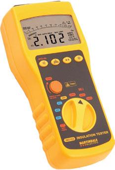
Figure 4.14 Insulation tester.
RCD tester
Where circuits are protected by an RCD we must carry out a test to ensure that the device will operate very quickly under fault conditions and within the time limits set by the IET Regulations. The instrument must, therefore, simulate a fault and measure the time taken for the RCD to operate. The instrument is, therefore, calibrated to give a reading measured in milliseconds to an in-service accuracy of 10%.
If you purchase good-quality ‘approved’ test instruments and leads from specialist manufacturers they will meet all the regulations and standards and therefore give valid test results. However, to carry out all the tests required by the IET Regulations will require a number of test instruments and this will represent a major capital investment in the region of £1,000.
Let us now consider the individual tests.
Assessment criteria 4.6
State the reasons why it is necessary to verify the continuity of circuit protective conductors, earthing conductors, bonding conductors and ring final circuit conductors
Assessment criteria 4.7
Specify and apply the methods for verifying the continuity of circuit protective conductors and ring final circuit conductors and interpreting the obtained results
Testing for continuity of protective conductors, including main and supplementary equipotential bonding (IET Regulation 643.2)
The objective of the test is to ensure that the circuit protective conductor (CPC) is correctly connected, is electrically sound and has a total resistance that is low enough to permit the overcurrent protective device to operate within the disconnection time requirements of IET Regulation 411.4.201, should an earth fault occur. Every protective conductor must be separately tested from the main earthing terminal of the installation to verify that it is electrically sound and correctly connected, including the protective equipotential and supplementary bonding conductors as shown in Fig 4.15 of this chapter and Fig 3.106 of Chapter 3. The IET Regulations describe the need to consider additional protection by supplementary equipotential bonding in situations where there is a high risk of electric shock, such as kitchens and bathrooms (IET Regulation 415.2).
Definition
A protective earthing conductor needs to form a low resistance path because it will enable any fault current to become high in value and isolate a circuit quickly.
A d.c. test using an ohmmeter continuity tester is suitable where the protective conductors are of copper or aluminium up to 35 mm2. The test is made with the supply disconnected, measuring from the main earthing terminal of the installation to the far end of each CPC, as shown in Fig. 4.16. The resistance of the long test lead is subtracted from these readings to give the resistance value of the CPC. The result is recorded on an installation schedule such as that given in Appendix 6 of the IET Regulations. A satisfactory test result for the bonding conductors will be in the order of 0.05 Ω or less (IET Guidance Note 3).
 Key fact
Supplementary bonding is also used when circuit disconnection times cannot be achieved.
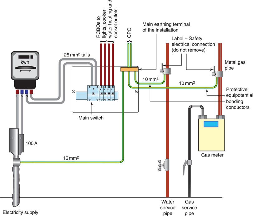
Figure 4.15 Cable Sheath Earth Supplies (TN-S System) showing earthing and main protective equipotential bonding arrangements.
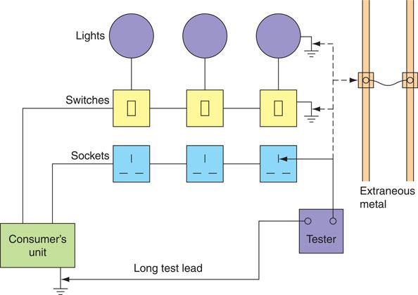
Figure 4.16 Testing continuity of protective conductors.
Where steel conduit or trunking forms the protective conductor, the standard test described above may be used, but additionally the enclosure must be visually checked along its length to verify the integrity of all the joints.
If the inspecting engineer has grounds to question the soundness and quality of these joints then the phase earth loop impedance test described later in this chapter should be carried out.
If, after carrying out this further test, the inspecting engineer still questions the quality and soundness of the protective conductor formed by the metallic conduit or trunking, then a further test can be done using an a.c. voltage not greater than 50 V at the frequency of the installation and a current approaching 1.5 times the design current of the circuit, but not greater than 25 A.
This test can be done using a low-voltage transformer and suitably connected ammeters and voltmeters, but a number of commercial instruments are available, such as the Clare tester, which give a direct reading in ohms. Because fault currents will flow around the earth fault loop path, the measured resistance values must be low enough to allow the overcurrent protective device to operate quickly. For a satisfactory test result, the resistance of the protective conductor should be consistent with those values calculated for a line conductor of similar length and cross-sectional area. Values of resistance per metre for copper and aluminium conductors are given in Table I1 of the On-Site Guide. The resistances of some other metallic containers are given in Table 4.1 of this book.
Definition
The circuit protective conductor within all PVC flat profile cable with the exception of 1 mm² is smaller than the live conductors. This means that its resistance will be higher.
Metallic sheath |
Size (mm) |
Resistance at 20°C (mΩ/m) |
|---|---|---|
Conduit |
20 |
1.25 |
25 |
1.14 |
|
32 |
0.85 |
|
Trunking |
50 × 50 |
0.949 |
75 × 75 |
0.526 |
|
100 ×100 |
0.337 |
Example
The CPC for a ring final circuit is formed by a 1.5 mm2 copper conductor of 50 m approximate length. Determine a satisfactory continuity test value for the CPC using the value given in Table I1 of the On-Site Guide.
Table I1 gives resistance/metre for a 1.5 mm2 copper conductor = 12.10 mΩ/m
The protective conductor resistance values calculated by this method can only be an approximation since the length of the CPC can only be estimated. Therefore, in this case, a satisfactory test result would be obtained if the resistance of the protective conductor was about 0.6 Ω. A more precise result is indicated by the earth fault loop impedance test which is carried out later in the sequence of tests.
Testing for continuity of ring final circuit conductors (IET Regulation 643.2)
The objective of the test is to ensure that all ring circuit cables are continuous around the ring; that is, that there are no breaks and no interconnections in the ring, and that all connections are electrically and mechanically sound. This test also verifies the polarity of each socket outlet. The test is made with the supply disconnected, using an ohmmeter as follows. Disconnect and separate the conductors of both legs of the ring at the main fuse. There are three steps to this test:
Step 1
Measure the resistance of the line conductors (L1 and L2), the neutral conductors (N1 and N2) and the protective conductors (E1 and E2) at the mains position as shown in Fig. 4.17. End-to-end live and neutral conductor readings should be approximately the same (i.e. within 0.05 Ω) if the ring is continuous. The protective conductor reading will be 1.67 times as great as these readings if 2.5/1.5 mm cable is used. Record the results on a table such as that shown in Table 4.2.
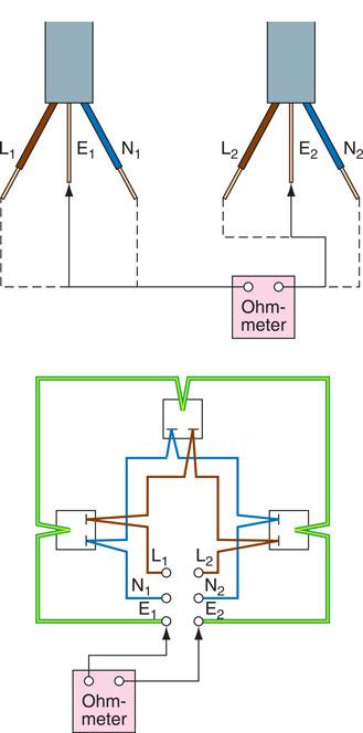
Figure 4.17 Step 1 test: measuring the resistance of phase, neutral and protective conductors.
Step 2
The live and neutral conductors should now be temporarily joined together as shown in Fig. 4.18. An ohmmeter reading should then be taken between live and neutral at every socket outlet on the ring circuit. The readings obtained should be substantially the same, provided that there are no breaks or multiple loops in the ring. Each reading should have a value of approximately half the live and neutral ohmmeter readings measured in Step 1 of this test. Sockets connected as a spur will have a slightly higher value of resistance because they are fed by only one cable, while each socket on the ring is fed by two cables. Record the results on a table such as that shown in Table 4.2.
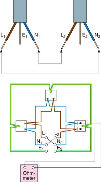
Figure 4.18 Step 2 test: connection of mains conductors and test circuit conditions.
Step 3
Where the CPC is wired as a ring, for example where twin and earth cables or plastic conduit is used to wire the ring, temporarily join the live and CPCs together as shown in Fig. 4.19. An ohmmeter reading should then be taken between live and earth at every socket outlet on the ring. The readings obtained should be substantially the same provided that there are no breaks or multiple loops in the ring. This value is equal to R1 + R2 for the circuit. Record the results on an installation schedule such as that given in Appendix 6 of the IET Regulations or a table such as that shown in Table 4.2. The Step 3 value of R1 + R2 should be equal to (r1 + r2)/4, where r1 and r2 are the ohmmeter readings from Step 1 of this test (see Table 4.2).
Definition
The reason why R1 + R2 is a quarter of r1 + r2/4 is because the length of the circuit conductors have been halved and the area doubled.
Key fact
Any socket reading greater than the ring measurement indicates the use of a spur outlet. Only one unfused spur is allowed per socket outlet.
Assessment criteria 4.8
State the effects that cables connected in parallel and variations in cable length can have on insulation resistance values
Assessment criteria 4.9
Interpret and apply the procedures for completing insulation resistance testing
Testing insulation resistance (IET Regulation 643.3)
The objective of the test is to verify that the quality of the insulation is satisfactory and has not deteriorated or short-circuited. The test should be made at the consumer’s unit with the mains switch off, all fuses in place and all switches closed. Neon lamps, capacitors and electronic circuits should be disconnected, since they will respectively glow, charge up and be damaged by the test. There are two tests to be carried out using an insulation resistance tester, which must have a test voltage of 500 V d.c. for 230 V and 400 V installations. These are line and neutral conductors to earth and between line conductors. The procedures are:
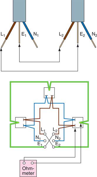
Figure 4.19 Step 3 test: connection of mains conductors and test circuit conditions.
Line and neutral conductors to earth:
1 Remove all lamps.
2 Close all switches and circuit-breakers.
3 Disconnect appliances.
4 Test separately between the line conductor and earth and between the neutral conductor and earth, for every distribution circuit at the consumer’s unit as shown in Fig. 4.20(a). Record the results on a schedule of test results such as that given in Appendix 6 of the IET Regulations.
Between line conductors:
1 Remove all lamps.
2 Close all switches and circuit-breakers.
3 Disconnect appliances.
4 Test between line and neutral conductors of every distribution circuit at the consumer’s unit as shown in Fig. 4.20(b) and record the result.
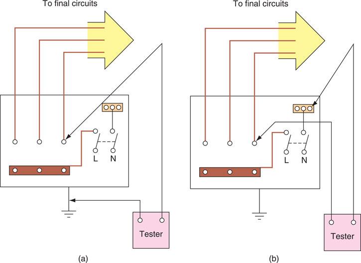
Figure 4.20 Insulation resistance test.
The insulation resistance readings for each test must be not less than 1.0 MΩ for a satisfactory result (IET Regulation 643.3.2).
Where the circuit includes electronic equipment that might be damaged by the insulation resistance test, a measurement between all live conductors (i.e. live and neutral conductors connected together) and the earthing arrangements may be made. The insulation resistance of these tests should be not less than 1.0 MΩ (IET Regulation 643.3.2).
Definition
Whilst an insulation resistance reading of 1 MΩ is acceptable to BS 7671 further investigation is recommended due to the possibility of a latent fault.
Although an insulation resistance reading of 1.0 MΩ complies with the regulations, the IET guidance notes tell us that much higher values than this can be expected and that a reading of less than 2 MΩ might indicate a latent, but not yet visible, fault in the installation. In these cases each circuit should be separately tested to obtain a reading greater than 2 MΩ.
Key fact
Doubling the length of a conductor will double its circuit resistance, However, it will halve its insulation resistance.
Assessment criteria 4.10
Explain why it is necessary to verify polarity
Assessment criteria 4.11
Interpret and apply the procedures for testing to identify correct polarity
Testing polarity (IET Regulation 643.6)
The object of this test is to verify that all fuses, circuit-breakers and switches are connected in the line or live conductor only, that all socket outlets are correctly wired and that Edison screw-type lampholders have the centre contact connected to the live conductor. It is important to make a polarity test on the installation since a visual inspection will only indicate conductor identification.
Definition
Polarity is defined in two ways, ensuring that switching only occurs through the line conductor and that all protective devices are also installed in the line conductor.
The test is done with the supply disconnected using an ohmmeter or continuity tester as follows:
1 Switch off the supply at the main switch.
2 Remove all lamps and appliances.
3 Fix a temporary link between the line and earth connections on the consumer’s side of the main switch.
4 Test between the ‘common’ terminal and earth at each switch position.
5 Test between the centre pin of any Edison screw lampholders and any convenient earth connection.
6 Test between the live pin (i.e. the pin to the right of earth) and earth at each socket outlet as shown in Fig. 4.21.
For a satisfactory test result the ohmmeter or continuity meter should read very close to zero for each test.
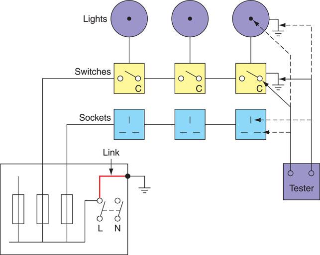
Figure 4.21 Polarity test.
Remove the test link and record the results on a schedule of test results such as that given in Appendix 6 of the IET Regulations.
Testing polarity – supply connected
Using an approved voltage indicator such as that shown at Fig. 4.2 or test lamp and probes that comply with the HSE Guidance Note GS 38, again carry out a polarity test to verify that all fuses, circuit-breakers and switches are connected in the live conductor. Test from the common terminal of switches to earth, the live pin of each socket outlet to earth and the centre pin of any Edison screw lamp holders to earth. In each case the voltmeter or test lamp should indicate the supply voltage for a satisfactory result.
Assessment criteria 4.12
Specify and apply the methods for measuring earth electrode resistance and correctly interpreting the results
Testing earth electrode resistance (IET Regulation 643.7.2)
When an earth electrode has been sunk into the general mass of earth, it is necessary to verify the resistance of the electrode. The general mass of earth can be considered as a large conductor that is at zero potential. Connection to this mass through earth electrodes provides a reference point from which all other voltage levels can be measured. This is a technique that has been used for a long time in power distribution systems.
Definition
Using the centre contact to confirm polarity does not apply to Edison screw types E14 and E27.
The resistance to earth of an electrode will depend upon its shape, size and the resistance of the soil. Earth rods form the most efficient electrodes. A rod of about 1 m will have an earth electrode resistance of between 10 and 200 Ω. Even in bad earthing conditions, a rod of about 2 m will normally have an earth electrode resistance that is less than 500 Ω in the United Kingdom. In countries that experience long dry periods of weather the earth electrode resistance may be thousands of ohms. In the past, electrical engineers used the metal pipes of water mains as an earth electrode, but the recent increase in the use of PVC pipe for water mains now prevents the use of water pipes as the means of earthing in the United Kingdom, although this practice is still permitted in some countries. IET Regulation 542.2.2 recognizes the use of the following types of earth electrodes:
• earth rods or pipes;
• earth tapes or wires;
• earth plates;
• earth electrodes embedded in foundations;
• welded metallic reinforcement of concrete structures;
• other suitable underground metalwork;
• lead sheaths or other metallic coverings of cables.
The earth electrode is sunk into the ground, but the point of connection should remain accessible (IET Regulation 542.4.2). The connection of the earthing conductor to the earth electrode must be securely made with a copper conductor complying with Table 54.1 and IET Regulation 542.3.2 as shown in Fig. 4.22.
The installation site must be chosen so that the resistance of the earth electrode does not increase above the required value due to climatic conditions such as the soil drying out or freezing, or from the effects of corrosion (IET Regulations 542.2.1 and 4).
Under fault conditions the voltage appearing at the earth electrode will radiate away from the electrode like the ripples radiating away from a pebble thrown into a pond. The voltage will fall to a safe level in the first 2 or 3 m away from the point of the earth electrode.
The basic method of measuring earth electrode resistance is to pass a current into the soil through the electrode and to measure the voltage required to produce this current.
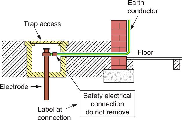
Figure 4.22 Termination of an earth electrode.
IET Regulation 643.7.2 demands that where earth electrodes are used they should be tested. If the electrode under test forms part of the earth return for a TT installation in conjunction with an RCD, Guidance Note 3 of the IET Regulations describes the following method:
Safety first
When testing an earth electrode the installation supply should be isolated since all protective bonding conductors are required to be disconnected for the test.
1 Disconnect the installation protective equipotential bonding from the earth electrode to ensure that the test current passes only through the earth electrode.
2 Switch off the consumer’s unit to isolate the installation.
3 Using a line earth loop impedance tester, test between the incoming line conductor and the earth electrode.
4 Reconnect the protective bonding conductors when the test is completed.
Record the result on a schedule of test results such as that given in Appendix 6 of the IET Regulations.
The IET Guidance Note 3 tells us that an acceptable value for the measurement of the earth electrode resistance would be less than 200 Ω. Providing the first five tests were satisfactory, the supply may now be switched on and the final tests completed with the supply connected.
Key fact
Loop impedance values in BS 7671 must be multiplied by 0,8.
Assessment criteria 4.13
Identify the earth fault loop paths for the following systems: TN-S, TN-C-S and TT
Assessment criteria 4.14
State the methods for verifying protection by automatic disconnection of the supply
Earth fault loop impedance Zs
The three most common earthing systems are:
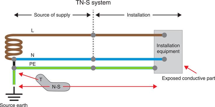
Figure 4.23 A TN-S system uses the armouring of the supply cable to provide a low resistance earth fault path.
• TN-S;
• TN-C-S;
• TT.
TN-S earthing systems use the supply armouring to create a low-resistance path to carry the fault current back to the supply transformer.
Definition
TN-S earthing uses the supply cable armouring to carry any fault current.
TN-C-S earthing systems make use of a protective earthing neutral (PEN) also known as a combined earthing neutral (CNE), which links the CPC and neutral. Line to CPC faults therefore become line to neutral faults but the loop impedance values are lower. Because of other installations sharing the same neutral there is a danger of faults being caused in other installations, for instance, through a break in the neutral conductor, which could bring about certain dangerous potential differences. To counter this the supply will be earthed at multiple points, which is why it is also known as protective multiple earthing. Because of the previous issue of sharing a neutral, PME earthing is not permitted in such places as: petrol stations, caravans and marinas.
Definition
TN-C-S makes use of a PEN conductor which changes line to CPC faults to line to neutral faults.
TT earthing systems make use of an earth electrode commonly through an earth spike but not exclusively so. Again, the aim is to create a low resistance path but this time through the earth itself, with the supply transformer also being earthed in the same way. The problem with using the earth itself is that it is not a good conductor of electricity especially if the soil is dry. Therefore, because there is a high possibility that loop impedance values can be >200 Ω, BS 7671 states that TT systems must be protected by an RCD.
In order that an overcurrent protective device can operate successfully it must meet the required disconnection times of IET Regulation 411.3.2.2, that is, final circuits not exceeding 32 A shall have a disconnection time not exceeding 0.4 s.
To achieve this, the earth fault loop impedance value measured in ohms must be less than those values given in Appendix B of the On-Site Guide and Tables 41.2 and 41.3 of the IET Regulations. Bearing in mind, of course, that while values in the On-Site Guide and Guidance Note 3 can be taken directly, those in BS 7671 cannot. This is because values within BS 7671 have not been corrected regarding conductors attaining full operational temperature and therefore the working value is 80% of those listed.
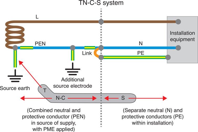
Figure 4.24 Neutral and protective conductors are combined up to the installation but separated within.
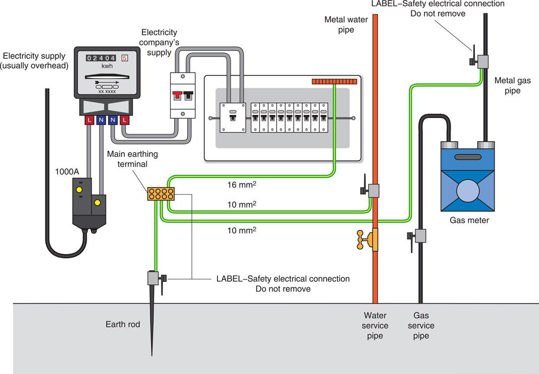
Figure 4.25 A TT earthing system operates by using an earthing electrode.
Values of the earth fault loop impedance may be verified by means of an earth fault loop impedance test, which is described in the next section. The formula is:
Definition
A TT earthing system uses an earthing electrode but if high earth loop impedance values are recorded then RCD protection must be in place.
Here ZE is the impedance of the supply side of the earth fault loop. The actual value will depend upon many factors: the type of supply, the ground conditions, the distance from the transformer, etc. The value can be obtained from the area electricity companies, but typical values are 0.35 Ω for TN-C-S (protective multiple earthing, PME) supplies and 0.8 Ω for TN-S (cable sheath earth) supplies as described a little earlier in this chapter. Also in the above formula, R1 is the resistance of the line conductor and R2 is the resistance of the earth conductor. The complete earth fault loop path is shown in Fig. 4.26. Values of R1 + R2 have been calculated for copper and aluminium conductors and are given in Table I1 of the On-Site Guide.
Definition
ZE represents the impedance of the external supplier circuit.
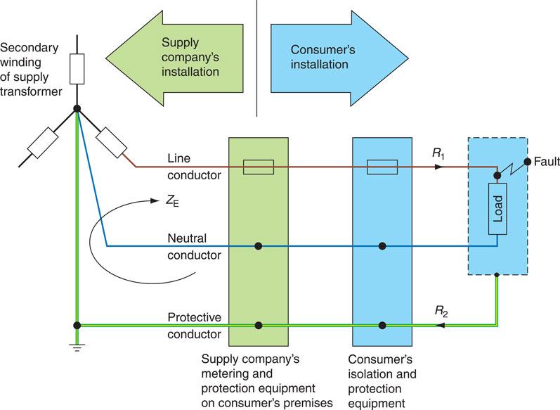
Figure 4.26 Earth fault loop path for a TN-S system.
Testing earth fault loop impedance – supply connected (IET Regulation 643.7.3)
The objective of this test is to verify that the impedance of the whole earth fault current loop line to earth is low enough to allow the overcurrent protective device to operate within the disconnection time requirements of IET Regulations 411.3.2.2, 411.4.201 and 411.4.202, should a fault occur.
Definition
Earth fault loop impedance testing must be carried out at the furthest point of the circuit. This will then gauge if sufficient fault current will flow in order to disconnect a circuit in the required time.
The whole earth fault current loop examined by this test comprises all the installation protective conductors, the main earthing terminal of the installation and protective bonding conductors, the earthed neutral point and the secondary winding of the supply transformer and the line conductor from the transformer to the point of the fault in the installation.
The test will, in most cases, be done with a purpose-made line earth loop impedance tester, which circulates a current in excess of 10 A around the loop for a very short time, so reducing the danger of a faulty circuit. The test is made with the supply switched on, and carried out from the furthest point of every final circuit, including lighting, socket outlets and any fixed appliances. Record the results on a schedule of test results.
Purpose-built testers give a readout in ohms and a satisfactory result is obtained when the loop impedance does not exceed the appropriate values given in Tables 41.2 and 41.3 of the IET Regulations. Table 41.3 gives a value of 2.73 ohm maximum for a circuit protected by a 16 A CB and 1.37 ohm maximum for a circuit protected by a 32 A CB.
Assessment criteria 4.15
Specify the methods for determining prospective fault current
The ways of determining values of prospective fault current are similar to obtaining earth loop impedance values in that they can be obtained by:
• enquiry directly from the service provider;
• measurement (earth loop impedance test instruments include a prospective fault current facility);
• calculation by Ohm’s law: I = V/R.
The prospective fault current must be obtained at the supply origin to ensure that switchgear and protective devices can withstand this level of voltage during fault conditions.
Definition
Measurement of prospective fault current is normally carried out at the supply origin, This is because its value will be at its highest and switchgear and protective devices can be accessed if they can withstand such values.
Assessment criteria 4.16
Specify the methods for testing the correct operation of residual current devices (RCDs)
Additional protection: testing of RCD – supply connected (IET Regulation 643.8)
The object of the test is to verify the effectiveness of the RCD, that it is operating with the correct sensitivity and to prove the integrity of the electrical and mechanical elements. The test must simulate an appropriate fault condition and be independent of any test facility incorporated in the device. When carrying out the test, all loads normally supplied through the device are disconnected.
The testing of a ring circuit protected by a general-purpose RCD to BS EN 61008 in a split-board consumer unit is carried out as follows:
1 Using the standard lead supplied with the test instrument, disconnect all other loads and plug in the test lead to the socket at the centre of the ring (i.e. the socket at the furthest point from the source of supply).
2 Set the test instrument to the tripping current of the device and at a phase angle of 0°.
3 Press the test button – the RCD should trip and disconnect the supply within 200 ms.
4 Change the phase angle from 0° to 180° and press the test button once again. The RCD should again trip within 200 ms. Record the highest value of these two results on a schedule of test results such as that given in Appendix 6 of the IET Regulations.
5 Now set the test instrument to 50% of the rated tripping current of the RCD and press the test button. The RCD should not trip within two seconds. This test is testing the RCD for inconvenience or nuisance tripping.
6 Finally, the effective operation of the test button incorporated within the RCD should be tested to prove the integrity of the mechanical elements in the tripping device. This test should be repeated every three months.
Key fact
An element involved in the testing of RCDs is to ensure that they are not the sole means of protection.
If the RCD fails any of the above tests it should be changed for a new one. Where the RCD has a rated tripping current not exceeding 30 mA and has been installed to reduce the risk associated with ‘basic’ and/or ‘fault’ protection, as indicated in IET Regulation 411.1, a residual current of 150 mA should cause the circuit-breaker to open within 40 ms.
Whereever RCDs are installed, a label shall be fixed near to the RCD stating ‘this device must be tested 6 monthly’ (IET Regulation 514.12.2). Previously the test period was 3 monthly.
Assessment criteria 4.17
State the methods used to check for the correct phase sequence
Assessment criteria 4.18
Explain why having the correct phase sequence is important
Check for phase sequence (IET Regulation 643.9)
Phase sequence is the order in which each phase of a three-phase supply reaches its maximum value. The normal phase sequence for a three-phase supply is brown–black–grey, which means that first brown, then black and finally the grey phase reaches its maximum value. A phase sequence tester can be an indicator which is, in effect, a miniature induction motor, with three clearly colour-coded connection leads. A rotating disc with a pointed arrow shows the normal rotation for phase sequence brown–black–grey. If the sequence is reversed, the disc rotates in the opposite direction to the arrow.
Alternatively, an indicator lamp showing the phase rotation by L1–L2–L3 may be used as shown in Fig. 4.27.
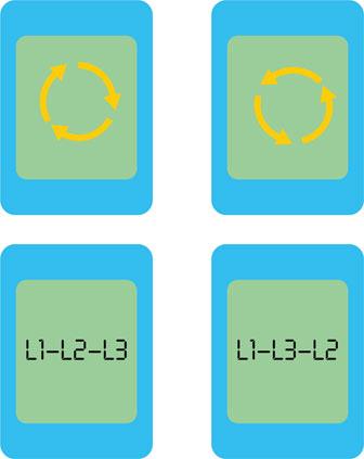
Figure 4.27 Phase rotation indicator instrument.
Instruments are also available that contain both of the above indications. The phase sequence is first of all checked at the point of entry to the building of the three-phase supply and the phase rotation noted. The phase sequence is then checked at any other three-phase distribution boards within the building. The objective is to obtain confirmation that the phase rotation of every three-phase distribution board is the same as that at the origin of the installation. Phase rotation and therefore direction of rotation of any three-phase motors affected by this action can be reversed by swapping over any two phases.
Assessment criteria 4.19
State the need for functional testing and identify items that need to be checked
Functional testing (IET Regulation 643.10)
The objective of the functional test is to confirm that all switchgear, controls and switches work as they were intended to work and are properly installed, mounted and adjusted. The little test button on any RCDs must also be activated to verify that it will trip under fault conditions.
Definition
Excessive lengths of cable can deny electrical loads some of its working voltage. This can be corrected by increasing the conductor size, which in turn lowers the circuit resistance.
Assessment criteria 4.20
Specify the methods used for verification of voltage drop
Assessment criteria 4.21
State the cause of volt-drop in an electrical installation
IET Regulation 525 states that the drop in voltage from the supply terminals to the fixed current-using equipment must not exceed 3% for lighting circuits and 5% for other uses of the mains voltage. That is, a maximum of 6.9 V for lighting and 11.5 V for other uses on a 230 V installation. The volt drop for a particular cable may be found from:
The factor is given in the tables of Appendix 4 of the IET Regulations and Appendix 6 of the On-Site Guide. One of the main reasons behind ascertaining volt drop is that if the circuit length is excessive then voltage will be dropped across the conductor but in doing so it deprives the load of some working voltage. This means that light can appear dim or even electrical motors can be sluggish or slow in operation. Excessive length of cable and volt drop issues are corrected by increasing the size of cable, since increasing the cross sectional area of a conductor lowers the circuit resistance.
Assessment criteria 4.22
State the appropriate procedures for dealing with customers and clients during the commissioning and certification process
Commissioning electrical systems
The commissioning of the electrical and mechanical systems within a building is a part of the ‘handing-over’ process of the new building by the architect and main contractor to the client or customer in readiness for its occupation and intended use. To ‘commission’ means to give authority to someone to check that everything is in working order. If it is out of commission, it is not in working order. Following the completion, inspection and testing of the new electrical installation, the functional operation of all the electrical systems must be tested before they are handed over to the customer. It is during the commissioning period that any design or equipment failures become apparent, and this testing is one of the few quality controls possible on a building services installation.
This is the role of the commissioning engineer, who must assure him or herself that all the systems are in working order and that they work as they were designed to work. This engineer must also instruct the client’s representative, or the staff who will use the equipment, in the correct operation of the systems as part of the handover arrangements.
The commissioning engineer must test the operation of all the electrical systems, including the motor controls, the fan and air conditioning systems, the fire alarm and emergency lighting systems. However, before testing the emergency systems, it is important to first notify everyone in the building of the intention to test the alarms so that they may be ignored during the period of testing. Commissioning has become one of the most important functions within the building project’s completion sequence. The commissioning engineer will therefore have access to all relevant contract documents, including the building specifications and the electrical installation certificates as required by the IET Regulations (BS 7671), and have a knowledge of the requirements of the Electricity at Work Regulations and the Health and Safety at Work Act.
The building will only be handed over to the client if the commissioning engineer is satisfied that all the building services meet the design specification in the contract documents and all the safety requirements.
Assessment criteria 5.1
Explain the purpose of and relationship between different types of testing documentation
Assessment criteria 5.2
State the information that must be contained within test certificates
Assessment criteria 5.3
Describe the certification process for a completed installation and identify the responsibilities of different relevant personnel in relation to the completion of the certification process
Assessment criteria 5.4
Explain the procedures and requirements, in accordance with the IET Wiring Regulations, IET Guidance Note 3 and where appropriate customer/client requirements for the recording and retention of certificates
Certification for Initial Verification (Regulation 644)
Following the completion of all new electrical work or additional work to an existing installation, the installation must be inspected and tested and an installation certificate issued and signed by a skilled or instructed person. The ‘skilled or instructed person’ must have a sound knowledge of the type of work undertaken, be fully versed in the inspection and testing procedures contained in the IET Regulations (BS 7671) and employ adequate testing equipment.
A certificate and test results shall be issued to those ordering the work in the format given in Appendix 6 of the IET Regulations. There are three model forms.
1 Electrical Installation Certificate: this is to be used when inspecting and testing a new installation or for alterations or additions to an existing installation. The documentation to be handed over to the client must include details of the extent of the installation covered by the certificate, a record of the inspection schedule and a copy of the test results plus a recommendation for the interval until the first periodic inspection (IET Regulation 644.1).

Figure 4.28 Testing and commissioning an electrical installation.
2 Minor Electrical Installation Works Certificate: this form is intended to be used for the addition of a socket outlet or lighting point to an existing circuit or for a repair or modification to the installation. The work does not extend to the addition of a new circuit. In this case, only the minor works certificate is given to the client upon completion (IET Regulation 644.4.201).
3 Periodic Inspection and Testing: all electrical installations must be periodically inspected and tested for the purpose of completing an electrical installation condition report (IET Regulation 651 and 653.1).
The documentation handed over to the client upon completion must include details of the extent of the installation covered by the report, a record of the inspection schedule, and a record of the test results plus a recommendation for the interval until the next periodic inspection (IET Regulation 653.2 and 4). Inspection schedules are discussed in more detail at the beginning of this chapter. In both cases the certificate must include the test values obtained from a ‘calibrated’ instrument which verify that the installation complies with the IET Regulations at the time of testing. The suggested frequency of periodic inspection intervals are given below:
• domestic installations – 10 years;
• commercial installations – 5 years;
• industrial installations – 3 years;
• agricultural installations – 3 years;
• caravan site installations – 1 year;
• caravans – 3 years but every year if used regularly;
• temporary installations on construction sites – 3 months.
Test your knowledge
When you have completed the questions check out the answers at the back of the book.
Note: More than one multiple-choice answer may be correct.
Learning outcome 1
1 All electrical test probes and leads used in applying safe isolation procedures must comply with certain standards. These standards are set by:
a. BS EN 60898
b. BS 7671
c. HSE Guidance Note GS 38
d. IET Regulations Part 2.
2 When carrying out safe isolation procedures for the purposes of safety, which of the following should be used?
a. neon screwdriver
b. a multimeter
c. volt stick
d. approved voltage indicator.
3 The Electricity at Work Regulations require that:
a. only persons who have the appropriate level of knowledge and experience can work with electricity
b. only duty holders can work with electricity
c. only time served electricians can work with electricity
d. only supervised apprentices can work with electricity.
4 Electrical safety is best achieved by:
a. isolating and securing the supply
b. switching the supply off
c. working during quiet hours
d. wearing electrician’s gloves.
5 Unless it can be justified, there exists an expectation that an electrician should always work on:
a. dead circuits
b. live circuits
c. RCD protected circuits
d. SELV circuits.
6 The legislation that prohibits live working except in exceptional circumstances is:
a. Provision and Use of Work Equipment Regulations (1992)
b. Personal Protective Equipment Regulations (1992)
c. BS 7671 Requirements for Electrical Installations
d. Electricity at Work Regulations (1989).
7 If more than one person is working on a circuit, which of the following should be used when carrying out safety isolation procedure?
a. mortise clasp
b. multi-lock hasp
c. cable ties
d. multi-key lock.
8 Which statutory regulation ensures the safe inspection of all manufactured, purchased and installed electrical systems?
a. Electricity at Work Regulation 1989
b. Health and Safety at Work Act 1974
c. Management of Health and Safety
d. COSHH.
9 The most serious outcome following a failure in carrying out safe isolation procedures would be:
a. incarceration
b. imprisonment
c. quicker timescales
d. death.
Learning outcome 2
10 ‘To ensure that all the systems within a building work as they were intended to work’ is one definition of the purpose of:
a. testing electrical equipment
b. inspecting electrical systems
c. commissioning electrical systems
d. isolating electrical systems.
11 The person carrying out the initial verification of an installation is confirming that the installation complies with:
a. BS 7671 in every regard
b. BS 7671 so far as reasonably practicable
c. Health and Safety Executive Requirements
d. Electricity at Work Regulation 1989.
12 The reason for initial verification is to ensure that installed electrical equipment is the:
a. correct type and complies to British Standards
b. correct size and complies to British Standards
c. correct rating and complies to British Standards
d. correct colour and complies to British Standards.
13 Initial verification is carried out to make sure that the fixed installation:
a. is correctly selected and erected
b. is correctly finished and sealed
c. is not defective
d. is not visibly damaged.
14 Which of the following is required before an initial inspection is able to be carried out?
a. equipment costing
b. earthing system
c. maximum demand
d. supply characteristics.
e. Learning outcome 3
Learning outcome 3
15 Which of the following are the most appropriate human senses regarding electrical testing?
a. intuition and speech
b. taste and pain
c. touch and feel
d. touch and sight.
16 Inspection and testing should:
a. only be carried out when installation is complete
b. only be carried out midway during the installation
c. be carried out during the installation and on completion
d. be complete within one month of the installation erection.
17 Which of the following are most appropriate to verify initial verification?
a. basic protection
b. equipment suitability
c. termination of conductors and cable selection
d. designated storage areas.
18 Which of the following is most appropriate in establishing safety?
a. fault protection
b. basic protection
c. all systems comply with PELV
d. all systems have to be FELV.
19 Choose which option is correct:
a. inspection comes before testing
b. testing comes before inspection
c. testing is more important than inspection
d. inspection is more important than testing.
Learning outcome 4
20 Testing results should be compared to:
a. other installations
b. BS 7671
c. designer requirements
d. Electricity at Work Regulation 1989.
21 The first test to be carried out on initial verification is:
a. polarity
b. continuity of protective conductors
c. functional testing
d. earth loop impedance.
22 Establishing fault protection includes:
a. earthing of class II equipment
b. RCD protection if Ze in TT systems is high
c. equipotential bonding of extraneous conductive parts
d. earthing of class 1 equipment.
23 Why is continuity of protective conductors so important?
a. due to their colour they are easier to see
b. they are smaller than live conductors
c. they are larger than live conductors
d. they are safety critical.
24 What value of voltage should be used when calculating the resistance of supplementary bonding conductors?
a. 110 V
b. 50 V
c. 400 V
d. 230 V.
25 When testing a 230 V installation an insulation resistance tester must be set to a voltage of:
a. less than 50 V
b. 500 V
c. less than 500 V
d. greater than twice the supply voltage but less than 1000 V.
26 The value of a satisfactory insulation resistance test on each final circuit of a 230 V installation must be:
a. less than 1 Ω
b. less than 0.5 MΩ
c. not less than 0.5 MΩ
d. not less than 1 MΩ.
27 Instrument calibration certificates are usually valid for a period of:
a. 3 months
b. 1 year
c. 3 years
d. 5 years.
28 The correct order for the requirement regarding dead tests is:
a. continuity of CPC, live polarity and earth loop impedance
b. continuity of CPC, dead polarity and earth loop impedance
c. continuity of CPC, insulation resistance and earth loop impedance
d. continuity of CPC, insulation resistance, polarity.
29 To obtain R1 + R2 in a ring circuit the r1 + r2 measurement needs to be:
a. divided by a factor of 4
b. divided by a factor of 3
c. divided by a ratio of 1.67
d. multiplied by a ratio of 1.67.
30 Which of the following regarding testing ring final conductors is correct?
a. one unfused spur allowed, readings will be higher than R1 + R2
b. any number of unfused spurs allowed, readings will be higher than R1 + R2
c. any number of fused spurs allowed, readings will be higher than R1 + R2
d. one fused spur allowed, readings will be higher than R1 + R2.
31 For PVC flat profile cable aside from 1 mm2, the resistance value of the live conductors with respect to the CPC is equivalent to:
a. ratio of 1.67 – CPC readings are more than the neutral conductor
b. ratio of 1.67 – CPC readings are less than the line conductor
c. ratio of 1.67 – CPC readings are more than the line and neutral conductors
d. ratio of 1.67 – CPC readings are less than the line and neutral conductors.
32 A tong test instrument is also known as:
a. a continuity tester
b. a clip/clamp-on ammeter
c. an insulation resistance tester
d. a voltage indicator.
33 One objective of dead polarity is to verify that:
a. lampholder’s outer thread is connected to the line conductor
b. lampholder is fused
c. lampholder’s centre contact is connected to the neutral conductor
d. lampholder’s centre contact is connected to the line conductor.
34 Connecting circuits in parallel will:
a. reduce the total resistance
b. increase the total resistance
c. halve the total resistance
d. double the total resistance.
35 Increasing the length of a circuit will:
a. reduce its insulation resistance
b. increase its insulation resistance
c. halve its insulation resistance
d. double its insulation resistance.
36 Before carrying out an insulation resistance test, which of the following should be considered?
a. all sensitive loads removed
b. all loads and capacitors removed
c. value of supply voltage
d. switches off protective devices removed.
37 If a circuit returns an insulation resistance value of 1 MΩ, according to BS 7671:
a. the circuit does not comply
b. the circuit complies
c. no further investigation is required
d. further investigation is recommended.
38 The definition of polarity is:
a. functional switching takes place through all live conductors
b. functional switching takes place through the line conductor
c. functional switching takes place through the neutral conductor
d. functional switching takes place through the CPC.
39 Earth loop impedance values can be read directly from:
a. GN3
b. BS 7671
c. On-Site Guide
d. GS38.
40 Total earth loop impedance can be obtained by:
a. measuring Zs
b. inquiry of Ze and measuring R1 and R2
c. inquiry of Zs
d. measuring Ze and measuring R1 and R2.
41 Live polarity tests are carried out by connecting across which conductors?
a. line and line
b. neutral and line
c. phase and earth
d. line and earth.
42 To ensure that the breaking capacity of a CB is met, which of the following human senses needs to be used?
a. touch
b. sight
c. taste
d. sound.
Learning outcome 5
43 The recommended maximum inspection and re-test period for a domestic electrical installation is:
a. 3 months
b. 3 years
c. 5 years
d. 10 years.
44 What should be issued after the completion of two small additions to an existing circuit?
a. minor works certificate
b. two minor works certificates
c. electrical Installation Certificate to cover both circuits
d. two Electrical Installation Certificates.
45 Following the completion of a new installation, which of the following must be issued?
a. test results schedules
b. Electrical Installation Condition Report
c. Electrical Installation Certificate
d. inspection schedules.
46 Following completion of an installation the:
a. inspector keeps a copy of the electrical installation certificate
b. inspector keeps the original electrical installation certificate
c. customer keeps a copy of the electrical installation certificate
d. customer is given the original electrical installation certificate.
47 Use bullet points to state three reasons for testing a new electrical installation.
48 State five of the most important safety factors to be considered before electrical testing begins.
49 State the seven requirements of GS 38 when selecting probes, voltage indicators and measuring instruments.
50 Use bullet points to describe a safe isolation procedure of a final circuit fed from a CB in a distribution board.
51 IET Regulation 611.3 gives a checklist of about 20 items to be considered in the initial visual inspection of an electrical installation. Make a list of 10 of the most important items to be considered in the visual inspection process (perhaps by joining together similar items).
52 State three reasons why electricians must only use ‘approved’ test instruments.
53 State the first five tests to be carried out on a new electrical installation following a satisfactory ‘inspection’. For each test:
a. state the object (reason for) the test
b. state a satisfactory test result.
Classroom activities
Match one of the numbered boxes to each lettered box on the left.
Dead test values
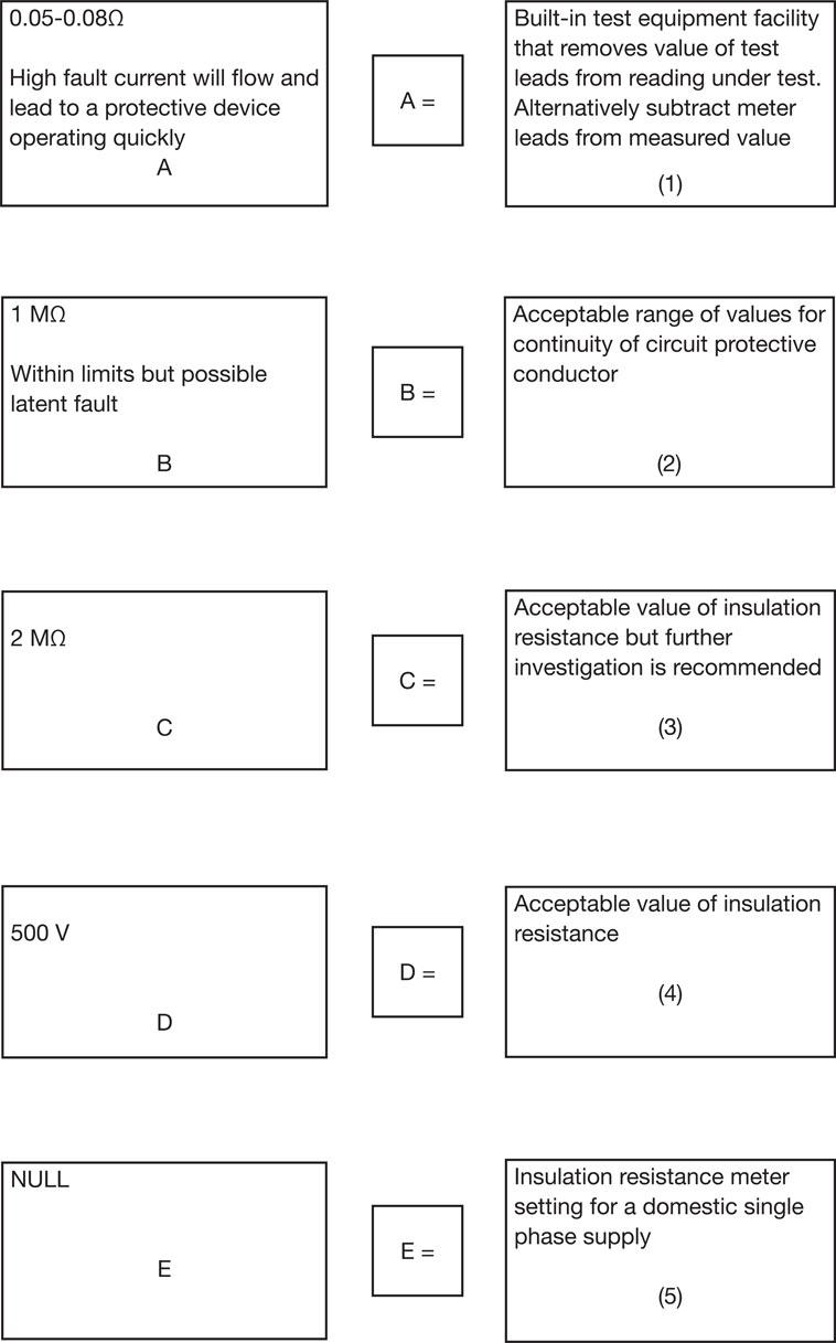
Testing position
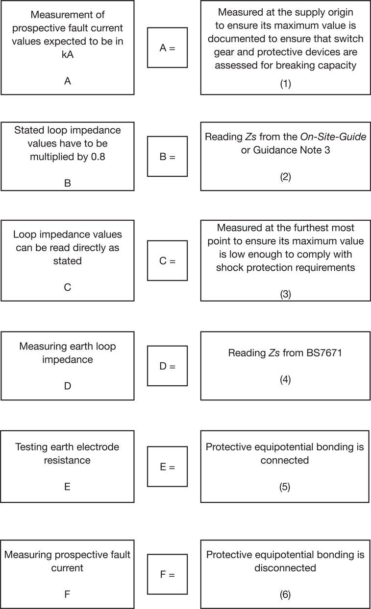
QELTK3/006 Understanding the principles, practices and legislation for the inspection, testing, commissioning and certification of electrotechnical systems and equipment in buildings, structures and the environment
Chapter checklist
Learning outcome |
Assessment criteria |
Page number |
|---|---|---|
1. Understand the principles, regulatory requirements and procedures for completing the safe isolation of an electrical circuit and complete electrical installations in preparation for inspection, testing and commissioning. |
1.1 State the requirements of the Electricity at Work Regulations 1989 for the safe inspection of electrical systems and equipment, in terms of those carrying out the work and those using the building during the inspection. |
266 |
1.2 Specify and undertake the correct procedure for completing safe isolation with regard to: • carrying out safe working practices • correct identification of circuit(s) to be isolated • identifying suitable points of isolation • selecting correct test and proving instruments in accordance with relevant industry guidance and standards • correct testing methods • selecting locking devices for securing isolation • correct warning notices • correct sequence for isolating circuits. |
267 |
|
1.3 State the implications of carrying out safe isolations to: • other personnel • customers/clients • public • building systems (loss of supply). |
270 |
|
1.4 State the implications of not carrying out safe isolations to: • self • other personnel • customers/clients • public • building systems (presence of supply). |
270 |
|
1.5 Identify all health and safety requirements that apply when inspecting, testing and commissioning electrical installations and circuits including those which cover: • working in accordance with risk assessments / permits to • work / method statements • safe use of tools and equipment • safe and correct use of measuring instruments • provision and use of PPE • reporting of unsafe situations. |
270 |
|
2. Understand the principles and regulatory requirements for inspecting, testing and commissioning electrical systems, equipment and components. |
2.1 State the purpose of and requirements for initial verification and periodic inspection of electrical installations |
271 |
2.2 Identify and interpret the requirements of the relevant documents associated with the inspection, testing and commissioning of an electrical installation, including: • Electricity at Work Regulations 1989 • IET wiring Regulations • IET Guidance Note 3. |
271 |
|
2.3 Specify the information that is required to correctly conduct the initial verification of an electrical installation in accordance with the IET Wiring Regulations and IET Guidance Note 3. |
273 |
|
3. Understand the regulatory requirements and procedures for completing the inspection of electrical installations. |
3.1 Identify the items to be checked during the inspection process for given electrotechnical systems and equipment, and their locations as detailed in the IET Wiring Regulations. |
274 |
3.2 State how human senses (sight, touch etc.) can be used during the inspection process. |
275 |
|
3.3 State the items of an electrical installation that should be inspected in accordance with IET Guidance Note 3. |
274 |
|
3.4 Specify the requirements for the inspection of the following: • earthing conductors • circuit protective conductors • protective bonding conductors • main bonding conductors • supplementary bonding conductors • isolation • type and rating of overcurrent protective devices. |
275 |
|
4. Understand the regulatory requirements and procedures for the safe testing and commissioning of electrical installations. |
4.1 State the tests to be carried out on an electrical installation in accordance with the IET Wiring Regulations and IET Guidance Note 3. |
276 |
4.2 Identify the correct instrument for the test to be carried out in terms of: • the instrument is fit for purpose • identifying the right scale/settings of the instrument appropriate to the test to be carried out. |
277 |
|
4.3 Specify the requirements for the safe and correct use of instruments to be used for testing and commissioning, including: • checks required to prove that test instruments and leads are safe and functioning correctly • the need for instruments to be regularly checked and calibrated and that this be done in accordance with the requirements of the IET Wiring Regulations and other relevant guidance documents (HSE guidance document GS38). |
281 |
|
4.4 Explain why it is necessary for test results to comply with standard values and state the actions to take in the event of unsatisfactory results being obtained. |
276 |
|
4.5 Explain why testing is carried out in the exact order as specified in the IET Wiring Regulations and IET Guidance Note 3 |
276 |
|
4.6 State the reasons why it is necessary to verify the continuity of circuit protective conductors, earthing conductors, bonding conductors and ring final circuit conductors. |
282 |
|
4.7 Specify and apply the methods for verifying the continuity of circuit protective conductors and ring final circuit conductors and interpreting the obtained results. |
282 |
|
4.8 State the effects that: • cables connected in parallel • variations in cable length can have on insulation resistance values. |
286 |
|
4.9 Interpret and apply the procedures for completing insulation resistance testing, including: • precautions to be taken before conducting insulation resistance tests • methods of testing insulation resistance • the required test voltages and minimum insulation resistance values for circuits operating at various voltages. |
286 |
|
4.10 Explain why it is necessary to verify polarity. |
287 |
|
4.11 Interpret and apply the procedures for testing to identify correct polarity. |
287 |
|
4.12 Specify and apply the methods for measuring earth electrode resistance and correctly interpreting the results. |
289 |
|
4.13 Identify the earth fault loop paths for the following systems: • TN-S • TN-C-S • TT. |
290 |
|
4.14 State the methods for verifying protection by automatic • disconnection of the supply, including: • the measurement of the earth fault loop impedance (Zs) and external impedance (Ze) • establishing Ze from enquiry • calculate the value of Zs from given information • comparing Zs and the maximum tabulated figures as specified in the IET Wiring Regulations. |
290 |
|
4.15 Specify the methods for determining prospective fault current. |
294 |
|
4.16 Specify the methods for testing the correct operation of residual current devices (RCDs). |
294 |
|
4.17 State the methods used to check for the correct phase sequence |
295 |
|
4.18 Explain why having the correct phase sequence is important. |
295 |
|
4.19 State the need for functional testing and identify items that need to be checked. |
296 |
|
4.20 Specify the methods used for verification of voltage drop. |
296 |
|
4.21 State the cause of volt-drop in an electrical installation. |
296 |
|
4.22 State the appropriate procedures for dealing with customers and clients during the commissioning and certification process, including: • Ensuring the safety of customers and clients during the completion of work activities • Keeping customers and clients informed during the process • Labelling electrical circuits, systems and equipment that is yet to be commissioned • Providing customers and clients with all appropriate documentation upon work completion. |
297 |
|
5. Understand the procedures and requirements for the completion of electrical installation certificates and related documentation. |
5.1 Explain the purpose of and relationship between: • an Electrical Installation Certificate • a Minor Electrical Installation Works Certificate • schedule of Inspections • schedule of Test results. |
297 |
5.2 State the information that must be contained within; • an Electrical Installation Certificate • a Minor Electrical Installation Works Certificate • Schedule of Inspections • Schedule of Test Results. |
297 |
|
5.3 Describe the certification process for a completed installation and identify the responsibilities of different relevant personnel in relation to the completion of the certification process |
298 |
|
5.4 Explain the procedures and requirements, in accordance with the IET Wiring Regulations, IET Guidance Note 3 and where appropriate customer/client requirements for the recording and retention of completed: • Electrical Installation Certificates • Minor Electrical Installation Works Certificates • Schedules of Inspections • Schedules of Test Results. |
298 |