CHAPTER 3
EAL Unit ELEC3/04a
Electrical installation planning, preparing and designing

Learning outcomes
When you have completed this chapter you should:
1. Understand how to plan for the installation of wiring systems and equipment.
2. Understand protection against overcurrent.
3. Understand earthing and protection.
4. Understand the electrical design procedure.
5. Understand how to prepare the worksite.
Assessment criteria 1.1
Interpret statutory and non-statutory requirements for the planned installation
Statutory laws
Acts of Parliament are made up of Statutes. Statutory Regulations have been passed by Parliament and have, therefore, become laws. Non-compliance with the laws of this land may lead to prosecution by the Courts and possible imprisonment for offenders.
We shall now look at some of the Statutory Regulations as they apply not only to the employers, employees and contractors within the electrical industry, but equally to visitors on site.
 Definition
Statutory Regulations are acts of parliament and must be met. Non-statutory regulations are technical documents and should be thought of as codes of practice.
 Key fact
There may be regional differences in some Statutory Laws such as The Health and Safety at Work Act as they apply to Northern Ireland and Wales, Where this is relevant, colleges should seek the advice of the examination board,
The Health and Safety at Work Act 1974
Many governments have passed laws aimed at improving safety at work, but the most important recent legislation has been the Health and Safety at Work Act 1974. This Act should be thought of as an umbrella Act that other statutory legislation sit under. The purpose of the Act is to provide the legal framework for stimulating and encouraging high standards of health and safety at work; the Act puts the responsibility for safety at work on both workers and managers.
Duty of care
The employer has a duty to care for the health and safety of employees (Section 2 of the Act). To do this he or she must ensure that:
• the working conditions and standard of hygiene are appropriate;
• the plant, tools and equipment are properly maintained;
• the necessary safety equipment – such as personal protective equipment (PPE), dust and fume extractors and machine guards – is available and properly used;
• the workers are trained to use equipment and plant safely.

Figure 3.1 Both workers and managers are responsible for health and safety on site.
Failure to comply with the Health and Safety at Work Act is a criminal offence and any infringement of the law can result in heavy fines, a prison sentence or both. This would apply to an employer who could be prosecuted if they knowingly allow an employee to work and that employee places other people at risk of possible injury.
Employees have a duty to care for their own health and safety and that of others who may be affected by their actions, including fellow employees and members of the public (Section 7 of the Act). To do this they must:
• take reasonable care to avoid injury to themselves or others as a result of their work activity;
• cooperate with their employer, helping him or her to comply with the requirements of the Act;
• not interfere with or misuse anything provided to protect their health and safety.
The Electricity at Work Regulations 1989 (EWR)
This legislation came into force in 1990 and replaced earlier regulations such as the Electricity (Factories Act) Special Regulations 1944. The regulations are made under the Health and Safety at Work Act 1974, and enforced by the Health and Safety Executive. The purpose of the regulations is to ‘require precautions to be taken against the risk of death or personal injury from electricity in work activities’.
Section 4 of the EWR tells us that ‘all systems must be constructed so as to prevent danger …, and be properly maintained … Every work activity shall be carried out in a manner which does not give rise to danger … In the case of work of an electrical nature, it is preferable that the conductors be made dead before work commences.’
The EWR do not tell us specifically how to carry out our work activities but they can be used in a court of law as evidence to claim compliance of other statutory requirements. If proceedings were brought against an individual for breaking the EWR, the only acceptable defence would be ‘to prove that all reasonable steps were taken and all diligence exercised to avoid the offence’ (Regulation 29).
An electrical contractor could reasonably be expected to have ‘exercised all diligence’ if the installation was wired according to the IET Wiring Regulations (see below). However, electrical contractors must become more ‘legally aware’ following the conviction of an electrician for manslaughter at Maidstone Crown Court in 1989. The court accepted that an electrician had caused the death of another man as a result of his shoddy work in wiring up a central heating system. He received a nine-month suspended prison sentence. This case has set an important legal precedent, and in future any tradesman or professional who causes death through negligence or poor workmanship risks prosecution and possible imprisonment.
The EWR is split into 16 regulations of its own. These regulations apply to any person who is engaged with electrical work: employers, the self-employed and employees, including certain classes of trainees.
Regulation 1 Citation and commencement
The first regulation puts the EWR into its context and cites that the EWR came into force on 1 April 1990.
Regulation 2 Interpretation
Brings about certain terms used in the EWR such as how we define terms such as: system, conductor and even what we mean by danger.
A system, for instance, is defined as:
an electrical system in which all the electrical equipment is, or may be, electrically connected to a common source of electrical energy, and includes such source and such equipment.
This means that the term ‘system’ includes all the constituent parts of a system, including the conductors and all the electrical equipment that fits within it.
‘Electrical equipment’ as defined in the regulations includes every type of electrical equipment from, for example, a 400 kV overhead line to a battery-powered hand lamp. The reason that the EWR apply to even low powered equipment is that although the risk of electric shock might be low, there might still be a risk of explosion for example.
A very important distinction is made regarding the terms ‘charged’ and ‘live’.
This is because when electricians carry out safe isolation procedures they must ensure that all forms of energy are removed from a circuit including any batteries or other devices such as capacitors that can store charge.
Consequently, the term ‘dead’ means: a conductor that is not ‘live’ nor ‘charged’.
Regulation 3 Persons on whom duties are imposed by these regulations
This regulation gives a clear statement of who the EWR applies to and makes a statement:
It shall be the duty of every employee while at work to comply with the provisions of these regulations in so far as they relate to matters which are within his/her control.
This means that a trainee electrician, although not fully qualified, must adhere to the EWR as well as always cooperating with their employer. Moreover, any office worker for instance must realize where their expertise and authority lie and cannot interfere with electrical equipment.
The EWR also defines the distinction between the terms ‘Absolute’ and ‘Reasonably Practicable’. Absolute means that something must be met irrespective of time or cost, whilst reasonably practicable means that a duty holder must decide the extent of the risks involved with the job in question against the costs involved as well as the actual difficulty in implementing safeguards.
Regulation 4 Systems, work activities and protective equipment
The definition of a system has already been defined above, but this regulation ensures that systems are designed so that as far as is reasonably practicable they do not pose a danger to anybody. This includes scheduling maintenance activities so that the equipment selected for that system must be fit for purpose.
Regulation 5 Strength and capability of electrical equipment
This regulation ensures that the system and all related equipment can withstand certain electromechanical/chemical stresses and temperature rises during normal operation, overload conditions and even fault current.
Regulation 6 Adverse or hazardous environments
The regulation draws attention to the kinds of adverse conditions where danger could arise if equipment is not designed properly or fit for purpose. This consideration includes impact damage, weather conditions, temperature, and even explosive conditions such as dust rich environments.
Regulation 7 Insulation, protection and placing of conductors
This regulation looks at the danger surrounding electric shock, and looks to insulate conductors or place/shield them so that people cannot directly touch any live parts and therefore receive either an electric shock or burn.
Regulation 8 Earthing or other suitable precautions
This regulation looks at how systems are protected to ensure that danger and specifically electric shock is minimized if faults occur. Both basic and fault protection measures apply, which includes earthing, bonding, separation and insulation of live parts.
Regulation 9 Integrity of referenced conductors
The objective of this regulation is to prevent certain conductors that are designed for electrical safety from being altered, which then brings about danger of electric shock. One of the most efficient earthing systems is called PME, which links the line and neutral conductors. However, any interference or fault in combined conductors can bring about possibly high dangerous voltages being developed across parts not normally live and therefore bringing about danger of electric shock.
Regulation 10 Connections
The objective of this regulation is to define the requirement regarding joints and connection. It specifies that all electrical connections need to be both mechanically and electrically strong as well as being suitable for use. In essence all electrical connections need to be low in resistance, but a problem occurs when joints are not formed properly because they create high resistance joints, which in turn creates areas where power is not normally dissipated and electrical fires are created.
Regulation 11 Means for protecting from excess of current
The objective of this regulation is the requirement to include protective devices to interrupt the supply when excess current is drawn. This is normally provided through fuses and circuit-breakers as well as additional protection through RCDs.
Regulation 12 Means for cutting off the supply and for isolation
The objective of this regulation is to install where necessary a suitable means of electrical isolation. For instance, if the control equipment of an electrical motor is in a different room to the motor, then the control equipment must be encased in a lockable enclosure.
It is worth reminding readers that ‘isolation’ means that all forms of energy are removed from a circuit, including any batteries or other devices such as capacitors that can store charge.
Regulation 13 Precautions for work on equipment made dead
This regulation ensures that adequate precautions shall be taken to prevent electrical equipment which has been made dead from becoming live when work is carried out on or near that equipment. In essence what this regulation is proposing is that electricians always carry out a safe isolation procedure. The regulation also states that where reasonable a written procedure known as a permit to work is used to authorize and control electrical maintenance.
Regulation 14 Work on or near live conductors
This regulation ensures that no person shall be engaged in any work activity on or so near any live conductor (other than one suitably covered with insulating material so as to prevent danger) where danger may arise unless:
a. it is unreasonable in all the circumstances for it to be dead; and
b. it is reasonable in all the circumstances for him to be at work on or near it while it is live; and
c. suitable precautions (including where necessary the provision of suitable protective equipment) are taken to prevent injury.
In other words, there is an expectation that electricians only work on dead supplies unless there is a reason against it and you can justify that reason. The regulation also specifies that the test instrument used to establish that a circuit is dead has to be fit for purpose or ‘approved’. Also included is mention of procedures regarding working in and around overhead power lines as well as quoting the Health and Safety at Work Act 1974 with regard to the provision of suitably trained first aiders at places of work.
Regulation 15 Working space, access and lighting
This regulation ensures that for the purposes of stopping injury, adequate working space, adequate means of access, and adequate lighting shall be provided when working with electrical equipment. For instance, when live conductors are in the immediate vicinity adequate space would allow electricians to pull back away from the conductors without hazard as well as allowing space for people to pass one another safely without hazard.
Regulation 16 Persons to be competent to prevent danger and injury
This regulation ensures that people practising with electrical work are: technically knowledgeable, experienced and competent to carry out that work activity. Electrical apprentices can engage in electrical work activity but must be supervised accordingly.
The main objective of the regulation is to ensure that people are not placed at risk due to a lack of skills on the part of themselves or others in dealing with electrical equipment.
Remember, the EWR 1989 regulations if defied can be used in any proceedings for an offence under this regulation.
6 Pack Regulations
As was previously highlighted the Health and Safety at Work Act 1974 is the main umbrella act that other statutory acts are drawn from. Alongside it five other acts form what is known as the 6 Pack Regulations and are shown below:
The Management of Health and Safety at Work Regulations 1999
The Health and Safety at Work Act 1974 places responsibilities on employers to have robust health and safety systems and procedures in the workplace. Directors and managers of any company that employs more than five employees can be held personally responsible for failures to control health and safety. The Management of Health and Safety at Work Regulations 1999 tell us that employers must systematically examine the workplace, the work activity and the management of safety in the establishment through a process of ‘risk assessments’. A record of all significant risk assessment findings must be kept in a safe place and be available to an HSE inspector if required. Information based on these findings must be communicated to relevant staff and, if changes in work behaviour patterns are recommended in the interests of safety, they must be put in place. The process of risk assessment is considered in detail later in this chapter.
Risks that may require a formal assessment in the electrical industry might be:
• working at heights;
• using electrical power tools;
• falling objects;
• working in confined places;
• electrocution and personal injury;
• working with ‘live’ equipment;
• using hire equipment;
• manual handling – pushing – pulling – lifting;
• site conditions – falling objects – dust – weather – water – accidents and injuries.
And any other risks that are particular to a specific type of workplace or work activity.
Personal Protective Equipment (PPE) at Work Regulations 1998
PPE is defined as all equipment designed to be worn, or held, to protect against a risk to health and safety. This includes most types of protective clothing, and equipment such as eye, foot and head protection, safety harnesses, lifejackets and high-visibility clothing. Under the Health and Safety at Work Act, employers must provide free of charge any PPE and employees must make full and proper use of it.
 Safety first
Always wear or use the PPE (personal protective equipment) provided by your employer for your safety.

Figure 3.2 Always wear appropriate personal protective equipment for the task at hand.
Provision and Use of Work Equipment Regulations 1998
These regulations tidy up a number of existing requirements already in place under other regulations such as the Health and Safety at Work Act 1974, the Factories Act 1961 and the Offices, Shops and Railway Premises Act 1963. The Provision and Use of Work Equipment Regulations 1998 place a general duty on employers to ensure minimum requirements of plant and equipment. If an employer has purchased good-quality plant and equipment which is well maintained, there is little else to do. Some older equipment may require modifications to bring it into line with modern standards of dust extraction, fume extraction or noise, but no assessments are required by the regulations other than those generally required by the Management Regulations 1999 discussed previously.
Workplace Health, Safety and Welfare Regulations 1992
This regulation specifies the general requirements and expectation of accommodation standards for nearly all workplaces. A breach of this regulation would be seen as a crime, punishable following any successful conviction.
The Control of Substances Hazardous to Health Regulations 2002 (COSSH)

Figure 3.3 Asbestos is an extremely toxic substance when it breaks down and causes lung disease.
The original COSHH Regulations were published in 1988 and came into force in October 1989. They were re-enacted in 1994 with modifications and improvements, and the latest modifications and additions came into force in 2002.
The COSHH Regulations control people’s exposure to hazardous substances in the workplace. Regulation 6 requires employers to assess the risks to health from working with hazardous substances, to train employees in techniques that will reduce the risk and provide personal protective equipment (PPE) so that employees will not endanger themselves or others through exposure to hazardous substances. Employees should also know what cleaning, storage and disposal procedures are required and what emergency procedures to follow. The necessary information must be available to anyone using hazardous substances as well as to visiting HSE Inspectors. Hazardous substances include:
1 any substance that gives off fumes causing headaches or respiratory irritation;
2 man-made fibres that might cause skin or eye irritation (e.g. loft insulation);
3 acids causing skin burns and breathing irritation (e.g. car batteries, which contain dilute sulphuric acid);
4 solvents causing skin and respiratory irritation (strong solvents are used to cement together PVC conduit fittings and tube);
5 fumes and gases causing asphyxiation (burning PVC gives off toxic fumes);
6 cement and wood dust causing breathing problems and eye irritation;
7 exposure to asbestos – although the supply and use of the most hazardous asbestos material is now prohibited, huge amounts were installed between 1950 and 1980 in the construction industry and much of it is still in place today.
In their latest amendments, the COSHH Regulations focus on giving advice and guidance to builders and contractors on the safe use and control of asbestos products. These can be found in Guidance Notes EH 71 or visit www.hse.uk/hiddenkiller.
Remember: where PPE is provided by an employer, employees have a duty to use it to safeguard themselves.
Working at Height Regulations
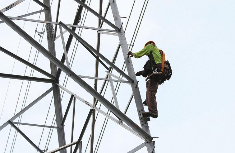
Figure 3.4 Working at height is a risk that requires a formal assessment in the electrical industry.
Working above ground level creates added dangers and slows down the work rate of the electrician. New Work at Height Regulations came into force on 6 April 2005. Every precaution should be taken to ensure that the working platform is appropriate for the purpose and in good condition. This is especially important since the main cause of industrial deaths comes from working at height.
Manual Handling Operations Regulations 1992 (as amended)
In effect, any activity that requires an individual to lift, move or support a load will be classified as a manual handling task. More than a third of all reportable injuries are believed to involve incorrect lifting techniques or carrying out manual handling operations without using mechanical lifting devices. Companies will also train their personnel through specific persons being appointed as manual handling advisors or safety representatives who will carry out both induction and refresher training in order to educate their workforce on correct lifting techniques and manual handling procedures.
Health and Safety (display screen equipment) Regulations 1992
These regulations are concerned with providing specific parameters on the expected safety and health requirements and implications for those personnel who work with display screen equipment. The equipment must be scrutinized so that it is not a source of risk for operators and should include the:
• display screen;
• keyboard;
• user space;
• chair;
• lighting (glare);
• software.
The Construction (Design and Management) Regulations 1994
The Construction (Design and Management) Regulations (CDM) are aimed at improving the overall management of health, safety and welfare throughout all stages of the construction project.
The person requesting that construction work commence, the client, must first of all appoint a ‘duty holder’, someone who has a duty of care for health, safety and welfare matters on-site. This person will be called a ‘planning supervisor’. The planning supervisor must produce a ‘pre-tender’ health and safety plan and coordinate and manage this plan during the early stages of construction. The client must also appoint a principal contractor who is then required to develop the health and safety plan made by the planning supervisor, and keep it up to date during the construction process to completion. The degree of detail in the health and safety plan should be in proportion to the size of the construction project and recognize the health and safety risks involved on that particular project. Small projects will require simple, straightforward plans; large projects, or those involving significant risk, will require more detail. The CDM Regulations will apply to most large construction projects but they do not apply to the following:
• construction work, other than demolition work, that does not last longer than 30 days and does not involve more than four people;
• construction work carried out inside commercial buildings such as shops and offices, which does not interrupt the normal activities carried out on those premises;
• construction work carried out for a domestic client;
• the maintenance and removal of pipes or lagging that form a part of a heating or water system within the building.
Definition
The ‘duty holder’ is someone who has a duty of care for health, safety and welfare matters on-site. This phrase recognizes the level of responsibility that electricians are expected to take on as part of their job in order to control electrical safety in the work environment.
The Electricity Safety, Quality and Continuity Regulations 2002 (formerly Electricity Supply Regulations 1989)
The Electricity Safety, Quality and Continuity Regulations 2002 are issued by the Department of Trade and Industry. They are statutory regulations that are enforceable by the laws of the land. They are designed to ensure a proper and safe supply of electrical energy up to the consumer’s terminals.
These regulations impose requirements upon the regional electricity companies regarding the installation and use of electric lines and equipment. The regulations are administered by the Engineering Inspectorate of the Electricity Division of the Department of Energy and will not normally concern the electrical contractor, except that it is these regulations that lay down the earthing requirement of the electrical supply at the meter position.
The regional electricity companies must declare the supply voltage and maintain its value between prescribed limits or tolerances.
The government agreed on 1 January 1995 that the electricity supplies in the United Kingdom would be harmonized with those of the rest of Europe. Thus the voltages used previously in low-voltage supply systems of 415 V and 240 V have become 400 V for three-phase supplies and 230 V for single-phase supplies. The permitted tolerances to the nominal voltage have also been changed from 6% to +10% and +6%. This gives a voltage range of 216–253 V for a nominal voltage of 230 V and 376–440 V for a nominal supply voltage of 400 V.
The next proposed change is for the tolerance levels to be adjusted to +10% of the declared nominal voltage (IET Regulation, Appendix 2:14).The frequency is maintained at an average value of 50 Hz over 24 hours so that electric clocks remain accurate.
Regulation 29 gives the area boards the power to refuse to connect a supply to an installation that in their opinion is not constructed, installed and protected to an appropriately high standard. This regulation would only be enforced if the installation did not meet the requirements of the IET Regulations for Electrical Installations.
Control of asbestos at work regulations
In October 2010 the HSE launched a national campaign to raise awareness among electricians and other trades of the risk to their health of coming into contact with asbestos. It is called the ‘Hidden Killer Campaign’ because approximately six electricians will die each week from asbestos-related diseases. For more information about asbestos hazards, visit www.hse.uk/hiddenkiller.
Non-statutory regulations
Statutory laws and regulations are written in a legal framework; some don’t actually tell us how to comply with the laws at an everyday level.
Definition
Statutory laws and regulations are written in a legal framework; some don’t actually tell us how to comply with the laws at an everyday level.
Non-statutory regulations and codes of practice interpret the statutory regulations, telling us how we can comply with the law.
Definition
Non-statutory regulations and codes of practice interpret the statutory regulations, telling us how we can comply with the law.
They have been written for every specific section of industry, commerce and situation, to enable everyone to comply with or obey the written laws. When the Electricity at Work Regulations (EWR) tell us to ‘ensure that all systems are constructed so as to prevent danger’ they do not tell us how to actually do this in a specific situation. However, the IET Regulations tell us precisely how to carry out our electrical work safely in order to meet the statutory requirements of the EWR. In Part 1 of the IET Regulations, at 114, it states: ‘the Regulations are non-statutory. They may, however, be used in a court of law in evidence to claim compliance with a statutory requirement.’ If your electrical installation work meets the requirements of the IET Regulations, you will also meet the requirements of EWR.
Over the years, non-statutory regulations and codes of practice have built upon previous good practice and responded to changes by bringing out new editions of the various regulations and codes of practice to meet the changing needs of industry and commerce.
We will now look at one non-statutory regulation, what is sometimes called ‘the electrician’s bible’, the most important set of regulations for anyone working in the electrical industry, the BS 7671: 2008 Requirements for Electrical Installations, IET Wiring Regulations 18th Edition.
The IET Wiring Regulations 18th Edition requirements for electrical installations to BS 7671: 2018
The Institution of Engineering and Technology Requirements for Electrical Installations (the IET Regulations) are non-statutory regulations. They relate principally to the design, selection, erection, inspection and testing of electrical installations, whether permanent or temporary, in and about buildings generally and to agricultural and horticultural premises, construction sites and caravans and their sites.
Paragraph 7 of the introduction to the EWR says: ‘the IET Wiring Regulations is a code of practice that is widely recognized and accepted in the United Kingdom and compliance with them is likely to achieve compliance with all relevant aspects of the Electricity at Work Regulations.’ The IET Wiring Regulations are the national standard in the United Kingdom and apply to installations operating at a voltage up to 1000 V a.c. They do not apply to electrical installations in mines and quarries, where special regulations apply because of the adverse conditions experienced there. The current edition of the IET Wiring Regulations is the 18th Edition 2018. The main reason for incorporating the IET Wiring Regulations into British Standard BS 7671: 2008 was to create harmonization with European Standards.
The IET Regulations take account of the technical intent of the CENELEC European Standards, which in turn are based on the IEC International Standards.
The purpose in harmonizing British and European Standards is to help develop a single European market economy so that there are no trade barriers to electrical goods and services across the European Economic Area.
Key fact
IET regulations
• They are the UK National Standard for all electrical work.
• They are the ‘electrician’s bible’.
• Comply with the IET Regulations and you also comply with Statutory Regulations (IET Regulations 1.14)
To assist electricians in their understanding of the regulations a number of guidance notes have been published. The guidance notes that I will frequently make reference to in this book are those contained in the On-Site Guide. Eight other guidance notes booklets are also currently available. These are:
• Selection and Erection;
• Isolation and Switching;
• Inspection and Testing;
• Protection against Fire;
• Protection against Electric Shock;
• Protection against Overcurrent;
• Special Locations;
• Earthing and Bonding.
These guidance notes are intended to be read in conjunction with the regulations.
The IET Wiring Regulations are the electrician’s bible and provide the authoritative framework of information for anyone working in the electrical industry.
Assessment criteria 1.2
Specify the criteria that affect the selection of wiring systems and equipment
Whilst the designer of any electrical installation is the person who interprets the electrical requirements of the customer and matches it to the regulations, an installer is also closely linked to this process and indeed on some projects the designer and senior installer are one and the same. The aim is to select a wiring system and equipment that is suitable for the actual environment.
Definition
The designer of any electrical installation is the person that interprets the electrical requirements of the customer within the regulations.
A large electrical installation project may require quite a few scheduled meetings with the customer in order to identify a precise specification to meet their needs. This will also give an opportunity to discuss any ergonomic and aesthetic requirements since being pleasing to the eye is often an important aspect of customer expectation. Other important considerations include scrutinizing the general characteristics of the electrical installation, including what earthing systems are available and the nature of the supply. Furthermore, compatibility of installed equipment with other services, as indicated in Part 3 of the regulations, is equally important in order to ensure that one system or even a single component does not affect an additional element.
Other considerations will include external influences such as ingress of moisture or other solid objects. Looking at maintainability on the other hand is the provision of maintenance and therefore an assessment of the frequency and quality required or expected will give an indication of the type of installation which is most appropriate. Another consideration is safety services such as the requirement to install such things as emergency lighting and fire detection. The protection and safety of the installation users is a paramount consideration, with due regard to Part 4 of BS 7671 the wiring regulations.
From this the size and quantity of all the materials, cables, control equipment and accessories can then be determined. This is called a ‘bill of quantities’. The suitability specification for the chosen wiring system will be largely determined by the building construction and the activities to be carried out in the completed building.
An industrial building, for example, will require an electrical installation that incorporates flexibility and mechanical protection, especially if moving heavy plant or vehicles are likely to or may possibly impact the installation. The possibility of vibration would also be a necessary consideration, for example the final connection to motors tends to be through a flexible conduit to offset any inherent juddering/vibration.
In a block of purpose-built flats, all the electrical connections must be accessible from one flat without intruding upon the surrounding flats. A loop-in conduit system, in which the only connections are at the light switch and outlet positions, would meet this requirement. For a domestic electrical installation an appropriate lighting scheme and multiple socket outlets for the connection of domestic appliances, all at a reasonable cost, are important factors, which can usually be met by a PVC-insulated and sheathed wiring system.
Temperature must also be a consideration either through the temperature of the ambient air, or through the harmful effects of heat and thermal radiation developed by electrical equipment. The impact of solar radiation for, example, is such that a PVC conduit for instance has to be fitted with expansion couplers every 5 m to make good any expansion.
Further contemplation may be made in relation to potential explosive atmospheres such as petrol stations or even such locations such as a flour mill, for example; given the rich content of the air they must not be exposed to an ignition source including the contacts of normal switches. This is why the possibility of dust, moisture content, chemical fumes and gas is part of the external influence assessment found in appendix 5 of the wiring regulations in order to reflect upon the correct index protection rating for equipment, which will determine what size body part can enter the accessory or if indeed extraction processes are required.
Index of Protection (IP) BS EN 60529
IET Regulation 416.2.1 tells us that where barriers and enclosures have been installed to prevent direct contact with live parts, they must afford a degree of protection not less than IP2X and IPXXB, total protection, but what does this mean? The Index of Protection is a code that gives us a means of specifying the suitability of equipment for the environmental conditions in which it will be used. The tests to be carried out for the various degrees of protection are given in the British and European Standard BS EN 60529.
The code is written as IP (Index of Protection) followed by two numbers XX.
The first number gives the degree of protection against the penetration of solid objects into the enclosure. The second number gives the degree of protection against water penetration. For example, a piece of equipment classified as IP45 will have barriers installed that prevent a 1 mm diameter rigid steel bar from making contact with live parts and be protected against the ingress of water from jets of water applied from any direction. Where a degree of protection is not specified, the number is replaced by an ‘X’, which simply means that the degree of protection is not specified, although some protection may be afforded. The ‘X’ is used instead of ‘0’ since ‘0’ would indicate that no protection was given. The index of protection codes are shown in Fig. 3.5.
Appendix 5 of the IET Regulations identifies the required IP classification for electrical equipment being used in hazardous conditions and requiring water protection as follows:
• IPX1 or IPX2 where water vapour occasionally condenses on electrical equipment;
• IPX3 where sprayed water forms a continuous film on the floor;
• IPX4 where equipment may be subjected to splashed water, e.g. construction sites;
• IPX5 where hosed water is regularly used, e.g. car washing;
• IPX6 for seashore locations, e.g. marinas and piers;
• IPX7 for locations which may become flooded, immersing equipment in water;
• IPX8 where electrical equipment is permanently immersed in water, e.g. swimming pools.
Appendix 5 of the IET Regulations also identifies the required IP classification to prevent dust and objects penetrating electrical equipment as follows:
• IP2X to prevent penetration by solid objects as thick as a finger, approximately 12 mm;
• IP3X to prevent penetration by small objects of which the smallest is 2.5 mm;
• IP4X to prevent penetration by very small objects of which the smallest is 1.0 mm;
• IP5X where light dust penetration would not harm the electrical equipment;
• IP6X where dust must not penetrate the equipment.
• IPXXB means total protection.
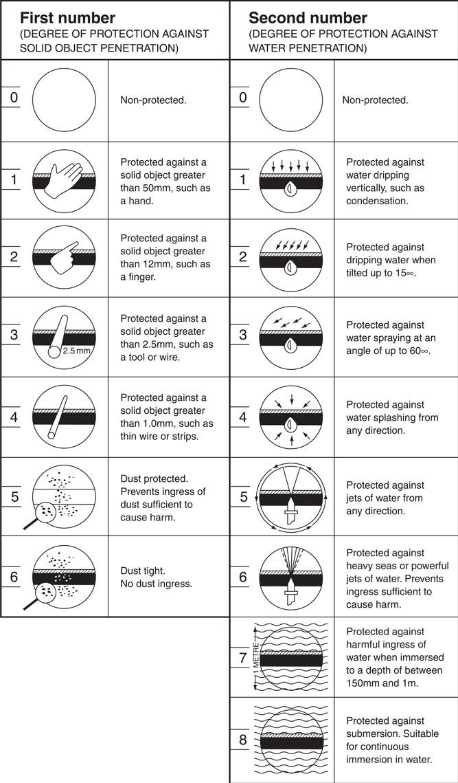
Figure 3.5 Index of protection codes.
External influences can also encourage corrosion. which means it has to be a major consideration. It can be improved by using galvanized steel conduit for instance, or encasing MICC conductors with a PVC oversheath. That said, electrolytic corrosion can occur when combining copper and aluminium with an aluminium conductor and copper crimp for instance. Galvanic action then occurs through a process known as dissimilar metal corrosion, therefore the designer must be mindful of such aspects. Certain locations would also be exposed to damaging winds and even seismic activity. Examining how the chosen installation method will affect the building structure is also an important consideration and we will examine that next.
Assessment criteria 1.3
Select wiring systems and equipment appropriate to the situation and use
An electrical installation is made up of many different electrical circuits:
• lighting circuits;
• power circuits;
• single-phase domestic circuits;
• three-phase industrial or commercial circuits environments;
• emergency systems;
• security systems.
Part 5 of the IET Regulations tells us that electrical equipment and materials must be chosen so that they are suitable for the actual environment in question. The condition of the location will dictate what kind of system is required taking into account: ambient temperature; the presence of moisture especially if that can lead to corrosion; potential impact damage; inherent vibration and exposure to solar radiation. PVC insulated and sheathed cables are manufactured cheaply for the domestic market, but are not necessary long lasting and lack any depth regarding mechanical protection. They would not necessarily be a suitable wiring type for a sub-main since they are mostly buried underground and therefore a PVC/SWA cable would be preferable. These two types of cable are shown in Figs. 3.50 and 3.51.
MI cables are waterproof, heatproof and corrosion-resistant with some mechanical protection. They are designed so that if the cable is flattened then the distance between the inner conductors remains the same. Often, given its qualities, it is the cable choice for hazardous or high-temperature installations such as oil refineries, chemical works, boiler houses and petrol pump installations. MI is also non-ageing, which is why it is often used in listed buildings reducing a need to replace the wiring, which would befall other wiring types. An MI cable with terminating gland and seal is shown in Fig. 3.52.
One-way lighting circuit
The simplest form of lighting circuit is a one way controlled light. This is where only one switch is used to operate the lights such as a bedroom light. In this circuit, the line conductor has a single pole overcurrent protective device (fuse or circuit-breaker) fitted in line with a switch which provides functional switching (on and off). A one way switch simply opens or closes the circuit as shown in Fig 3.6.
In a domestic installation or when using PVC/PVC cable running the line conductor to the switch and the neutral to the lamp is not possible so we use the three plate method and ‘loop’ the line through the ceiling rose as shown in Fig 3.8 or, we can use the joint box method shown in Fig 3.9.
The switch line, returning from the switch to the lamp, is the blue insulated conductor in the PVC/PVC cable (it is possible to buy cables with two brown insulated conductors). As this wire is a switched line, the regulations state we must indicate this can be live and therefore we add a brown sleeve to show the blue is not acting as the neutral. The wiring diagram of a 1 way lighting circuit using the joint box method is shown in Fig 3.9.
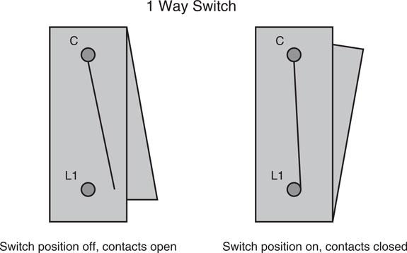
Figure 3.6 Shows how circuit is complete when common links to L1.

Figure 3.7 A circuit diagram for a 1 way lighting circuit.
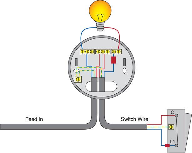
Figure 3.8 Wiring diagram of 1 way lighting circuit using the Loop in Method.
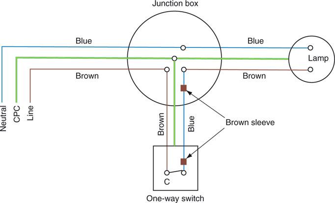
Figure 3.9 Wiring diagram of one-way switch control.
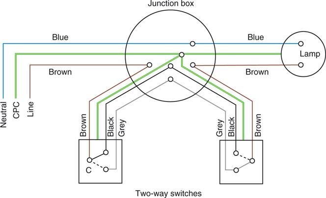
Figure 3.10 Wiring diagram of two-way switch control.
Two-way lighting circuit
A two-way lighting circuit is used where two separate switching positions are required such as a staircase with a switch at either end. The overcurrent protective device is fitted in the line conductor before it feeds the switches, controlling the supply to the light. A two-way switch differs from the one-way switch because the feed in is connected to either one or the other of the two outlet terminals. The switch acts as a changeover, switching the connections between the common and position 1 or the common and position 2 dependent on the switch position. Fig 3.10 shows the joint box method of wiring a two way lighting circuit.

Figure 3.11 Wiring diagram of intermediate switch control.
Intermediate switching
On a lighting circuit where the light requires three or more switches, an intermediate switch is used. This may be a staircase with a landing part way or a long corridor for example. The wiring is carried out in the same way as a two-way installation, with the intermediate switch or switches added between the two, two-way switches. Fig 3.11 shows the joint box method of wiring intermediate switch control.
Definition
Intermediate switching would typically be used in long corridors.
Junction boxes
When wiring a lighting circuit, the designer will look at the fittings and decide if it is possible or suitable to terminate multiple cables at the accessory. It may be decided that making the joints in a joint box is preferable and to run a cable to the switches or fittings for ease of terminations. Junction boxes with fixed terminals or adaptable boxes housing connector blocks, often referred to as RB4s, could be used. BS 7671 Regulation 526.3 requires all screw terminals to be accessible for maintenance once installed and this must be considered when designing such a circuit.
SELV lighting
Many spotlight type fittings work, use or operate using SELV (Separated Extra Low Voltage). For the system to be classified as SELV, the voltage must not exceed 50 V ac or 120V dc and the circuit protective conductor may not be connected to the load. This is achieved by use of a transformer to BS EN 61558-2-6, where the low voltage (230 V) circuit is connected to the primary side and the ELV fitting is connected to the secondary side. Plugs and sockets used for the connections must not be interchangeable so as to avoid the fittings being connected to a higher voltage than it is designed for.
Many SELV systems use LED lighting due to its high efficiency, however not all SELV transformers are dimmable.
Key fact
The limitation regarding an A1 ring circuit is not the number of sockets but the maximum area it can supply (100 m2).
Socket outlet Circuits
Whereas most equipment is wired on a radial circuit, it is common practice in the UK to wire BS1363 13A socket outlets on a ring final circuit. BS 7671 describes a ring final circuit as ‘starting and finishing at the distribution board, where it is connected to a 30A or 32A overcurrent protective device’.
The On-Site Guide describes this arrangement as an A1 circuit and while it does not limit the number of sockets that can be connected to this arrangement, it does give a maximum floor area that the circuit may feed as 100m2.
The minimum cable size for the live conductors of a ring final circuit is given as 2.5 mm2 when using thermoplastic cables (1.5 mm for mineral insulated cable as it has a higher current carrying capacity) and at first glance this looks like the cable is rated lower than the protective device and will not comply to other regulations. Due to the ring arrangement, the current will split within the circuit and this design is acceptable to British and European Standards. However, care should be taken when designing the circuit to provide reasonable sharing of the load in each leg of the ring.
The number of socket outlets on a ring final circuit is unlimited but the load will determine if more than one circuit is required. In this case, the designer should look to distribute permanently connected equipment across the circuits to avoid overloading any one circuit and reduce the inconvenience in the case of a fault or when maintenance is being carried out.
Number of socket outlets
When installing socket outlets they should be numerous enough and positioned such that all equipment can be connected conveniently without the need for extension leads. The On-Site Guide provides Table H7 in Appendix H to give guidance on the minimum numbers required in assorted locations.
Spurs
A socket that is not connected within the ring but fed via a single cable is known as a spur. The total number of un-fused spurs connected to a ring should not exceed the total number of sockets and stationary equipment connected directly to the ring. A non-fused spur should only feed one single or one twin socket outlet or a piece of permanently connected equipment to avoid overloading the cable feeding it. The connection to the ring final circuit should be made at the terminals of an existing socket outlet, the origin of the circuit or in a junction box, and the size of the live conductors should be 2.5 mm2 minimum. When a supply to more than one outlet is required and it is not possible to incorporate the addition into the ring, a fused connection unit (FCU) may be used.
The FCU may be connected directly into the ring or as a spur and incorporates a BS EN 1362 fuse. As the largest BS EN 1362 fuse is 13 A, this is the maximum load that can be drawn and the number of sockets fed by the FCU is only limited by the load being connected not exceeding 13 A. The total number of FCUs connected to the ring final circuit is unlimited.

Figure 3.12 Only one unfused spur is allowed per socket outlet.
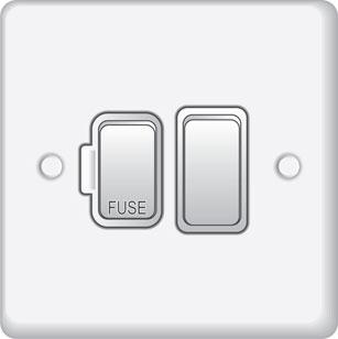
Figure 3.13 Switched Fused Connection Unit
As the wiring beyond the FCU is protected by a 13 A fuse, the cross sectional area of the live conductors can be reduced and a 1.5 mm2 cable is allowed (1 mm2 for mineral insulated cable).
Define the requirements of standard radial final socket circuits
The On-Site Guide also recognizes that socket outlets may be wired on radial final circuits. Table H2.1 classifies the circuits as A2 and A3 where an A2 circuit is protected by a 30 A or 32 A overcurrent protective device, wired in 4 mm2 thermoplastic cable (2.5 mm2 for MI cable) and a maximum floor area of 75 m2.
The A3 circuit uses 2.5 mm2 cable (1.5 mm2 for MI) and therefore the overcurrent protective device is reduced to 20 A. This circuit has a maximum floor area of 50 m2.
Standard circuit arrangements for loads and equipment
Common domestic circuits include cookers, showers and immersion heaters. All of these appliances are wired on radial final circuits and the rating of the circuit is determined by an assessment of the current demand of the appliance.
Water-heating circuits
Certain high current load equipment such as large water heaters, cookers and showers should be fitted with a double pole switch in order to isolate both the line and neutral conductors. A small, single-point over-sink type water heater may be considered as a permanently connected appliance and so may be connected to a ring circuit through a fused connection unit. A water heater of the immersion type is usually rated at a maximum of 3 kW, and could be considered as a permanently connected appliance, fed from a fused connection unit. However, many immersion heating systems are connected into storage vessels of about 150 litres in domestic installations, and the On-Site Guide states that immersion heaters fitted to vessels in excess of 15 litres should be supplied by their own dedicated circuit (On-Site Guide Appendix H5).
Therefore, immersion heaters must be wired on a separate radial circuit when they are connected to water vessels that hold more than 15 litres. Figure 3.20 shows the wiring arrangements for an immersion heater. Every switch must be a double-pole (DP) switch and out of reach of anyone using a fixed bath or shower when the immersion heater is fitted to a vessel in a bathroom.
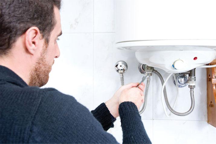
Figure 3.14 Immersion heaters in excess of 15 litres should be supplied by their own dedicated circuit and controlled through a double pole switch.
Key fact
Certain high current load equipment such as large water heaters, cookers and showers should be fitted with a double pole switch in order to isolate both the line and neutral conductors.
Supplementary equipotential bonding to pipework will only be required as an addition to fault protection (IET Regulation 415.2) if the immersion heater vessel is in a bathroom that does not have:
• all circuits protected by a 30 mA RCD; and also
• protective equipotential bonding (IET Regulation 701.415.2).

Figure 3.15 Immersion heater wiring.
Electric space-heating circuits
Electrical heating systems can be broadly divided into two categories: unrestricted local heating and off-peak heating.
Unrestricted local heating may be provided by portable electric radiators that plug into the socket outlets of the installation. Fixed heaters that are wall mounted or inset must be connected through a fused connection and incorporate a local switch, either on the heater itself or as a part of the fuse connecting unit. Heating appliances where the heating element can be touched must have a DP switch that disconnects all conductors. This requirement includes radiators that have an element inside a silica-glass sheath.
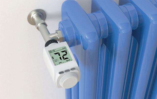
Figure 3.16 A radiator can be controlled through remote sensors and electronic wireless control.
Off-peak heating systems may provide central heating from storage radiators, ducted warm air or underfloor heating elements. All three systems use the thermal storage principle, whereby a large mass of heat-retaining material is heated during the off-peak period and allowed to emit the stored heat throughout the day. The final circuits of all off-peak heating installations must be fed from a separate supply controlled by an electricity board time clock.
When calculating the size of cable required to supply a single-storage radiator, it is good practice to assume a current demand equal to 3.4 kW at each point. This will allow the radiator to be changed at a future time with the minimum disturbance to the installation. Each storage heater must have a 20 A DP means of isolation adjacent to the heater and the final connection should be via a flex outlet. See Fig. 3.17 for wiring arrangements.
Ducted warm air systems have a centrally sited thermal storage heater with a high storage capacity. The unit is charged during the off-peak period, and a fan drives the stored heat in the form of warm air through large air ducts to outlet grilles in the various rooms. The wiring arrangements for this type of heating are shown in Fig. 3.18.
The single-storage heater is heated by an electric element embedded in bricks and rated between 6 and 15 kW depending upon its thermal capacity. A radiator of this capacity must be supplied on its own circuit, in cable capable of carrying the maximum current demand and protected by a fuse or circuit-breaker (CB) of 30, 45 or 60 A as appropriate. At the heater position, a DP switch must be installed to terminate the fixed heater wiring. The flexible cables used for the final connection to the heaters must be of the heat-resistant type.
Floor-warming installations use the thermal storage properties of concrete. Special cables are embedded in the concrete floor screed during construction. When current is passed through the cables they become heated, the concrete absorbs this heat and radiates it into the room. The wiring arrangements are shown in Fig. 3.19. Once heated, the concrete will give off heat for a long time after the supply is switched off and is, therefore, suitable for connection to an off-peak supply.
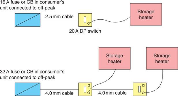
Figure 3.17 Possible wiring arrangements for storage heaters.
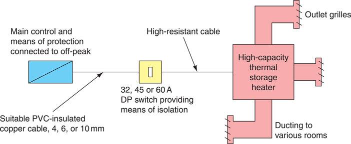
Figure 3.18 Ducted warm air heating system.
Underfloor heating cables installed in bathrooms or shower rooms must incorporate an earthed metallic sheath or be covered by an earthed metallic grid connected to the protective conductor of the supply circuit (IET Regulation 701.753).
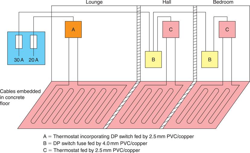
Figure 3.19 Floor-warming installations.
Emergency management systems
Certain systems are designed to respond during emergency situations, especially if the primary source of power fails.
Emergency lighting (BS 5266 and BS EN 1838)
Emergency lighting should be planned, installed and maintained to the highest standards of reliability and integrity, so that it will operate satisfactorily when called into action, no matter how infrequently this may be. Emergency lighting is not required in private homes because the occupants are familiar with their surroundings, but in public buildings people are in unfamiliar surroundings. In an emergency people do not always act rationally, but well illuminated and easily identified exit routes can help to reduce panic.
Emergency lighting is provided for two reasons: to illuminate escape routes, called ‘escape’ lighting; and to enable a process or activity to continue after a normal lights failure, called ‘standby’ lighting. Escape lighting is usually required by local and national statutory authorities under legislative powers. The escape lighting scheme should be planned so that identifiable features and obstructions are visible in the lower levels of illumination which may prevail during an emergency. Exit routes should be clearly indicated by signs and illuminated to a uniform level, avoiding bright and dark areas.

Figure 3.20 Escape routes should remain illuminated in the event of a powercut.
Standby lighting is required in hospital operating theatres and in industry, where an operation or process once started must continue, even if the mains lighting fails. Standby lighting may also be required for security reasons. The cash points in public buildings may need to be illuminated at all times to discourage acts of theft occurring during a mains lighting failure.
Emergency supplies
Since an emergency occurring in a building may cause the mains supply to fail, the emergency lighting should be supplied from a source that is independent from the mains supply. In most premises the alternative power supply would be from batteries, but generators may also be used. Generators can have a large capacity and duration, but a major disadvantage is the delay of time while the generator runs up to speed and takes over the load. In some premises a delay of more than 5 seconds is considered unacceptable, and in these cases a battery supply is required to supply the load until the generator can take over.
Definition
Emergency lighting is not required in private homes because the occupants are familiar with their surroundings, but in public buildings people are in unfamiliar surroundings. In an emergency people do not always act rationally, but well-illuminated and easily identified exit routes can help to reduce panic.
Definition
Emergency lighting is provided for two reasons: to illuminate escape routes, called ‘escape’ lighting; and to enable a process or activity to continue after a normal lights failure, called ‘standby’ lighting.
The emergency lighting supply must have an adequate capacity and rating for the specified duration of time (IET Regulation 313.2). BS 5266 and BS EN1838 state that after a battery is discharged by being called into operation for its specified duration of time, it should be capable of once again operating for the specified duration of time following a recharge period of no longer than 24 hours. The duration of time for which the emergency lighting should operate will be specified by a statutory authority but is normally 1–3 hours. The British Standard states that escape lighting should operate for a minimum of 1 hour.
Standby lighting operation time will depend upon financial considerations and the importance of continuing the process or activity.
There are two possible modes of operation for emergency lighting installations: maintained and non-maintained.
Maintained emergency lighting
In a maintained system the emergency lamps are continuously lit using the normal supply when this is available, and change over to an alternative supply when the mains supply fails. The advantage of this system is that the lamps are continuously proven healthy and any failure is immediately obvious. It is a wise precaution to fit a supervisory buzzer or LED indicator in the emergency supply to prevent accidental discharge of the batteries, since it is not otherwise obvious which supply is being used.
Definition
In a maintained system the emergency lamps are continuously lit using the normal supply when this is available, and change over to an alternative supply when the mains supply fails.
Maintained emergency lighting is normally installed in theatres, cinemas, discotheques and places of entertainment where the normal lighting may be dimmed or extinguished while the building is occupied. The emergency supply for this type of installation can also be supplied from a central battery, the emergency lamps being wired in parallel from the low-voltage supply as shown in Fig. 3.21. Escape sign lighting units used in commercial facilities should be wired in the maintained mode.

Figure 3.21 Maintained emergency lighting.
Non-maintained emergency lighting
In a non-maintained system the emergency lamps are only illuminated if the normal mains supply fails. Failure of the main supply de-energizes a solenoid and a relay connects the emergency lamps to a battery supply, which is maintained in a state of readiness by a trickle charge from the normal mains supply. When the normal supply is restored, the relay solenoid is energized, breaking the relay contacts, which disconnects the emergency lamps, and the charger recharges the battery. Figure 3.22 illustrates this arrangement.
The disadvantage with this type of installation is that broken lamps are not detected until they are called into operation in an emergency, unless regularly maintained. The emergency supply is usually provided by a battery contained within the luminaire, together with the charger and relay, making the unit self-contained.
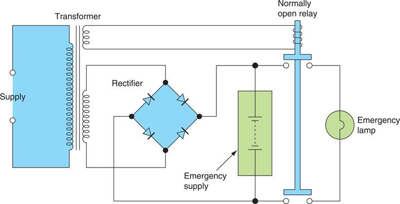
Figure 3.22 Non-maintained emergency lighting.
Definition
In a non-maintained system the emergency lamps are only illuminated if the normal mains supply fails.
Self-contained units are cheaper and easier to install than a central battery system, but the central battery can have a greater capacity and duration, and permit a range of emergency lighting luminaires to be installed.
Maintenance
The contractor installing the emergency lighting should provide a test facility that is simple to operate and secure against unauthorized interference, usually a simple key switch. The emergency lighting installation must be segregated completely from any other wiring, so that a fault on the main electrical installation cannot damage the emergency lighting installation (IET Regulation 528.1).
Figure 3.23 shows a trunking that provides for segregation of circuits. The batteries used for the emergency supply should be suitable for this purpose. Motor vehicle batteries are not suitable for emergency lighting applications, except in the starter system of motor-driven generators. The fuel supply to a motor-driven generator should be checked. The battery room of a central battery system must be well ventilated and, in the case of a motor-driven generator, adequately heated to ensure rapid starting in cold weather.
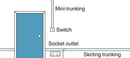
Figure 3.23a Typical installation of skirting trunking and mini-trunking.
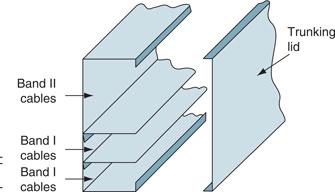
Figure 3.23b Segregation of cables in trunking.
The British Standard recommends that the full load should be carried by the emergency supply for at least one hour in every six months. After testing, the emergency system must be carefully restored to its normal operative state. A record should be kept of each item of equipment and the date of each test by a qualified or responsible person. It may be necessary to produce the record as evidence of satisfactory compliance with statutory legislation to a duly authorized person.
Self-contained units are suitable for small installations of up to about 12 units. The batteries contained within these units should be replaced about every five years, or as recommended by the manufacturer and be connected to the a.c. mains supply through a ‘test’ switch.
Avoiding shutdown of IT equipment
Every modern office now contains computers, and many systems are linked together or networked. Most computer systems are sensitive to variations or distortions in the mains supply and many computers incorporate filters that produce high-protective conductor currents of around 2 or 3 mA. This is clearly not a fault current, but is typical of the current that flows in the circuit protective conductor of IT equipment under normal operating conditions. IET Regulations 543.7.1 and 4 deal with the earthing requirements for the installation of equipment having high-protective conductor currents. IET Guidance Note 7 recommends that IT equipment should be connected to double sockets as shown in Fig. 5.13.
Key fact
IET regulations
Because of filters incorporated within computers, the cumulative effects with a bank of computers are that they can cause sufficiently high-protective conductor currents to cause nuisance tripping of RCDs.
Surge protection
A transient overvoltage or surge is a voltage spike of very short duration. It may be caused by a lightning strike or a switching action on the system. It sends a large voltage spike for a few microseconds down the mains supply, which is sufficient to damage sensitive electronic equipment. Supplies to computer circuits must be ‘clean’ and ‘secure’. Mainframe computers and computer networks are sensitive to mains distortion or interference, which is referred to as ‘noise’. Noise is mostly caused by switching an inductive circuit, which causes a transient spike, or by brush gear making contact with the commutator segments of an electric motor. These distortions in the mains supply can cause computers to ‘crash’ or provoke errors and are shown in Fig. 3.24.
To avoid this, a ‘clean’ supply is required for the computer network. This can be provided by taking the ring or radial circuits for the computer supplies from a point as close as possible to the intake position of the electrical supply to the building. A clean earth can also be taken from this point, which is usually one core of the cable and not the armour of an SWA cable, and distributed around the final wiring circuit. Alternatively, the computer supply can be cleaned by means of a filter such as that shown in Fig. 3.25 or by installing surge protection devices.
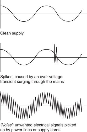
Figure 3.24 Distortion in the a.c. mains supply.
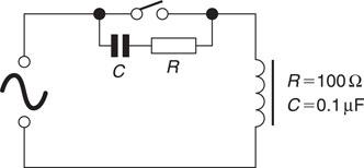
Figure 3.25 A simple noise suppressor.
Secure supplies
The mains electrical supply in the United Kingdom is extremely reliable and secure. However, the loss of supply to a mainframe computer or computer network for even a second can cause the system to ‘crash’, and hours, or even days, of work can be lost.
One solution to this problem is to protect ‘precious’ software systems with an uninterruptible power supply (UPS). A UPS is essentially a battery supply electronically modified to provide a clean and secure a.c. supply. The UPS is plugged into the mains supply and the computer systems are plugged into the UPS.
A UPS to protect a small network of, say, six PCs is physically about the size of one PC hard drive and is usually placed under or at the side of an operator’s desk. It is best to dedicate a ring or radial circuit to the UPS and either to connect the computer equipment permanently or to use non-standard outlets to discourage the unauthorized use and overloading of these special supplies by, for example, other workers or cleaning staff kettles.
Finally, remember that most premises these days contain some computer equipment and systems. Electricians intending to isolate supplies for testing or modification should first check and then check again before they finally isolate the supply in order to avoid loss or damage to computer systems.
A surge protection device is a device intended to limit transient over voltages, and to divert damaging surge currents away from sensitive equipment. Section 534 of the IET Regulations contain the requirements for the installation of surge protective devices (SPDs) to limit transient over voltages where required by section 443 of BS 7671:2018 or where specified by the designer.
Definition
A UPS is essentially a battery supply electronically modified to provide a clean and secure a.c. supply.
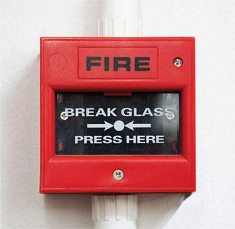
Figure 3.26 Fire alarm circuits are wired as either normally open or normally closed.
Fire alarm circuits (BS 5839 and BS EN 54-2: 1998)
Through one or more of the various statutory Acts, all public buildings are required to provide an effective means of giving a warning of fire so that life and property may be protected. An effective system is one that gives a warning of fire while sufficient time remains for the fire to be put out and any occupants to leave the building.
Fire alarm circuits are wired as either normally open or normally closed. In a normally open circuit, the alarm call points are connected in parallel with each other so that when any alarm point is initiated the circuit is completed and the sounder gives a warning of fire. The arrangement is shown in Fig. 3.27. It is essential for some parts of the wiring system to continue operating even when attacked by fire. For this reason the master control and sounders should be wired in MI or FP 200 cable. The alarm call points of a normally open system must also be wired in MI or FP 200 cable, unless a monitored system is used. In its simplest form this system requires a high-value resistor to be connected across the call-point contacts, which permits a small current to circulate and operate an indicator, declaring the circuit healthy. With a monitored system, PVC insulated cables may be used to wire the alarm call points.
Definition
In a normally closed circuit, the alarm call points are connected in series to normally closed contacts as shown in Fig. 3.33. When the alarm is initiated, or if a break occurs in the wiring, the alarm is activated.

Figure 3.27 A simple normally open fire alarm circuit.
In a normally closed circuit, the alarm call points are connected in series to normally closed contacts as shown in Fig. 3.28. When the alarm is initiated, or if a break occurs in the wiring, the alarm is activated. The sounders and master control unit must be wired in MI or FP 200 cable, but the call points may be wired in PVC insulated cable since this circuit will always ‘fail safe’.
Definition
Manually operated alarm call points should be provided in all parts of a building where people may be present, and should be located so that no one need walk for more than 30 m from any position within the premises in order to give an alarm.
Alarm call points
Manually operated alarm call points should be provided in all parts of a building where people may be present, and should be located so that no one need walk for more than 30 m from any position within the premises in order to give an alarm. A break glass manual call point is shown in Fig. 3.29. They should be located on exit routes and, in particular, on the floor landings of staircases and exits to the street. They should be fixed at a height of 1.4 m above the floor at easily accessible, well illuminated and conspicuous positions. Automatic detection of fire is possible with heat and smoke detectors. These are usually installed on the ceilings and at the top of stairwells of buildings because heat and smoke rise. Smoke detectors tend to give a faster response than heat detectors, but whether manual or automatic call points are used should be determined by their suitability for the particular installation. They should be able to discriminate between a fire and the normal environment in which they are to be installed.
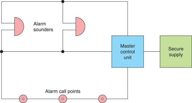
Figure 3.28 A simple normally closed fire alarm circuit.
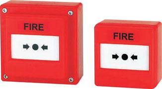
Figure 3.29 Breakglass manual call point.
Sounders
The sounders should produce a minimum of 65 dB, or 5 dB above any ambient sound which might persist for more than 30 seconds. If the sounders are to arouse sleeping persons then the minimum sound level should be increased to 75 dB at the bedhead. Bells, hooters or sirens may be used but in any one installation they must all be of the same type. Examples of sounders are shown in Fig. 3.30. Normal speech is about 5 dB.
Definition
The positions and numbers of sounders should be such that the alarm can be distinctly heard above the background noise in every part of the premises.
Fire alarm design considerations
Since all fire alarm installations must comply with the relevant statutory regulations, good practice recommends that contact be made with the local fire prevention officer at the design stage in order to identify any particular local regulations and obtain the necessary certification. Larger buildings must be divided into zones so that the location of the fire can be quickly identified by the emergency services. The zones can be indicated on an indicator board situated in, for example, a supervisor’s office or the main reception area. In selecting the zones, the following rules must be considered:
1 Each zone should not have a floor area in excess of 2000 m2.
2 Each zone should be confined to one storey, except where the total floor area of the building does not exceed 300 m2.
3 Staircases and very small buildings should be treated as one zone.
4 Each zone should be a single fire compartment. This means that the walls, ceilings and floors are capable of containing the smoke and fire.
At least one fire alarm sounder will be required in each zone, but all sounders in the building must operate when the alarm is activated. The main sounders may be silenced by an authorized person, once the general public have been evacuated from the building, but the current must be diverted to a supervisory buzzer, which cannot be silenced until the system has been restored to its normal operational state. A fire alarm installation may be linked to the local fire brigade’s control room by the telecommunication network, if the permission of the fire authority and local telecommunication office is obtained.
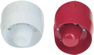
Figure 3.30 Typical fire alarm sounders.
The electricity supply to the fire alarm installation must be secure in the most serious conditions. In practice the most reliable supply is the mains supply, backed up by a ‘standby’ battery supply in case of mains failure. The supply should be exclusive to the fire alarm installation, fed from a separate switch fuse, painted red and labelled, ‘Fire Alarm – Do Not Switch Off’. Standby battery supplies should be capable of maintaining the system in full normal operation for at least 24 hours and, at the end of that time, be capable of sounding the alarm for at least 30 minutes.
Fire alarm circuits are Band 1 circuits and consequently cables forming part of a fire alarm installation must be physically segregated from all Band II circuits unless they are insulated for the highest voltage (IET Regulations 528.1 and 560.7.1).
Intruder alarms
The installation of security alarm systems in the United Kingdom is already a multi-million-pound business and yet it is also a relatively new industry. As society becomes increasingly aware of crime prevention, it is evident that the market for security systems will expand.
Definition
PIR detector units allow a householder to switch lighting units on automatically wherever the area covered is approached by a moving body whose thermal radiation differs from the background.
Not all homes are equally at risk, but all homes have something of value to a thief. Properties in cities are at highest risk, followed by homes in towns and villages, and at least risk are homes in rural areas. A nearby motorway junction can, however, greatly increase the risk factor. Flats and maisonettes are the most vulnerable, with other types of property at roughly equal risk. Most intruders are young, fit and foolhardy opportunists. They ideally want to get in and away quickly but, if they can work unseen, they may take a lot of trouble to gain access to a property by, for example, removing the glass from a window.
Most intruders are looking for portable and easily saleable items such as mobile phones, television sets, home computers, jewellery, cameras, silverware, money, cheque books or credit cards. The Home Office has stated that only 7% of homes are sufficiently protected against intruders, although 75% of householders believe they are secure. Taking the simplest precautions will reduce the risk, while installing a security system can greatly reduce the risk of a successful burglary.
Security lighting
Security lighting is the first line of defence in the fight against crime. A recent study carried out by Middlesex University has shown that in two London boroughs the crime figures were reduced by improving the lighting levels. Police forces agree that homes and public buildings that are externally well illuminated are a much less attractive target for the thief.
Definition
Security lighting is the first line of defence in the fight against crime.
Security lighting installed on the outside of the home may be activated by external detectors. These detectors sense the presence of a person outside the protected property and additional lighting is switched on. This will deter most potential intruders while also acting as courtesy lighting for visitors (Fig. 3.31).
Passive infra-red detectors
Passive infra-red (PIR) detector units allow a householder to switch on lighting units automatically whenever the area covered is approached by a moving body whose thermal radiation differs from the background. This type of detector is ideal for driveways or dark areas around the protected property. It also saves energy because the lamps are only switched on when someone approaches the protected area. The major contribution to security lighting comes from the ‘unexpected’ high-level illumination of an area when an intruder least expects it. This surprise factor often encourages the potential intruder to ‘try next door’.
PIR detectors are designed to sense heat changes in the field of view dictated by the lens system. The field of view can be as wide as 180°, as shown by the diagram in Fig. 3.32. Many of the ‘better’ detectors use a split lens system so that a number of beams have to be broken before the detector switches on the security lighting. This capability overcomes the problem of false alarms, and a typical PIR is shown in Fig. 3.33.
PIR detectors are often used to switch LED or tungsten halogen floodlights because, of all available luminaires, tungsten halogen and LEDs offer instant high-level illumination. Light fittings must be installed out of reach of an intruder in order to prevent sabotage of the security lighting system.

Figure 3.31 Security lighting reduces crime.
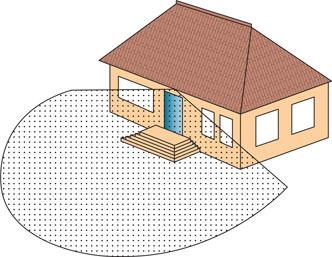
Figure 3.32 PIR detector and field of detection.
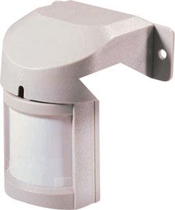
Figure 3.33 A typical PIR detector.
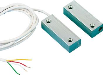
Figure 3.34 Proximity switches for perimeter protection.
Intruder alarm systems
Alarm systems are now increasingly considered to be an essential feature of home security for all types of homes and not just property in high-risk areas. An intruder alarm system serves as a deterrent to a potential thief and often reduces home insurance premiums. In the event of a burglary they alert the occupants, neighbours and officials to a possible criminal act and generate fear and uncertainty in the mind of the intruder, which encourages a more rapid departure. Intruder alarm systems can be broadly divided into three categories – those that give perimeter protection, space protection or trap protection. A system can comprise one or a mixture of all three categories.
Definition
An intruder alarm system serves as a deterrent to a potential thief and often reduces home insurance premiums.
Definition
A perimeter protection system places alarm sensors on all external doors and windows so that an intruder can be detected as soon as they attempt to gain access to the protected property.
A movement or heat detector placed in a room will detect the presence of anyone entering or leaving that room.
Trap protection places alarm sensors on internal doors and pressure pad switches under carpets on through routes between, for example, the main living area and the master bedroom.
A perimeter protection system places alarm sensors on all external doors and windows so that an intruder can be detected as he or she attempts to gain access to the protected property. This involves fitting proximity switches to all external doors and windows.
A movement or heat detector placed in a room will detect the presence of anyone entering or leaving that room. PIR detectors and ultrasonic detectors give space protection. Space protection does have the disadvantage of being triggered by domestic pets but it is simpler and, therefore, cheaper to install.
Perimeter protection involves a much more extensive and, therefore, expensive installation, but is easier to live with.
Trap protection places alarm sensors on internal doors and pressure pad switches under carpets on through routes between, for example, the main living area and the master bedroom. If an intruder gains access to one room he cannot move from it without triggering the alarm.
Proximity switches
These are designed for the discreet protection of doors and windows. They are made from moulded plastic and are about the size of a chewing-gum packet, as shown in Fig. 3.34. One moulding contains a reed switch, the other a magnet, and when they are placed close together the magnet maintains the contacts of the reed switch in either an open or closed position. Opening the door or window separates the two mouldings and the switch is activated, triggering the alarm.
PIR detectors
These are activated by a moving body that is warmer than the surroundings.
The PIR shown in Fig. 3.33 has a range of 12 m and a detection zone of 110° when mounted between 1.8 and 2 m high.

Figure 3.35 Intruder alarm sounder.
Figure 3.36 Intruder alarm control panel with remote keypad.
Intruder alarm sounders
Alarm sounders give an audible warning of a possible criminal act. Bells or sirens enclosed in a waterproof enclosure, such as shown in Fig. 3.35, are suitable.
It is usual to connect two sounders on an intruder alarm installation, one inside to make the intruder apprehensive and anxious, hopefully encouraging a rapid departure from the premises, and one outside. The outside sounder should be displayed prominently since the installation of an alarm system is thought to deter the casual intruder and a ringing alarm encourages neighbours and officials to investigate a possible criminal act.
Control panel
The control panel, such as that shown in Fig. 3.36, is at the centre of the intruder alarm system. All external sensors and warning devices radiate from the control panel. The system is switched on or off at the control panel using a switch or coded buttons. To avoid triggering the alarm as you enter or leave the premises, there are exit and entry delay times to allow movement between the control panel and the door.
Supply
The supply to the intruder alarm system must be secure and this is usually achieved by an a.c. mains supply and battery back-up. Nickel–cadmium rechargeable cells are usually mounted in the sounder housing box.
Optical fibre cables
The introduction of fibre-optic cable systems and digital transmissions will undoubtedly affect future cabling arrangements and the work of the electrician.
Networks based on the digital technology currently being used so successfully by the telecommunications industry are very likely to become the long-term standard for computer systems. Fibre-optic systems dramatically reduce the number of cables required for control and communications systems, and this will in turn reduce the physical room required for these systems. Fibre-optic cables are also immune to electrical noise when run parallel to mains cables and, therefore, the present rules of segregation and screening may change in the future. There is no spark risk if the cable is accidentally cut and, therefore, such circuits are intrinsically safe.
Optical fibre cables are communication cables made from optical-quality plastic, the same material from which spectacle lenses are manufactured. The energy is transferred down the cable as digital pulses of laser light as against current flowing down a copper conductor in electrical installation terms. The light pulses stay within the fibre-optic cable because of a scientific principle known as ‘total internal refraction’ which means that the laser light bounces down the cable and when it strikes the outer wall it is always deflected inwards and, therefore, does not escape out of the cable, as shown in Fig. 3.38.
The cables are very small because the optical quality of the conductor is very high and signals can be transmitted over great distances. They are cheap to produce and lightweight because these new cables are made from high-quality plastic and not high-quality copper. Single-sheathed cables are often called ‘simplex’ cables and twin-sheathed cables ‘duplex’, that is, two simplex cables together in one sheath. Multicore cables are available containing up to 24 single fibres.

Figure 3.37 Optical fibre cables.
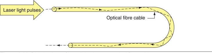
Figure 3.38 Digital pulses of laser light down an optical fibre cable.
Fibre-optic cables look like steel wire armour (SWA) cables (but of course are lighter) and should be installed in the same way and given the same level of protection as SWA cables. Avoid tight-radius bends if possible and kinks at all costs. Cables are terminated in special joint boxes that guarantee cable ends are cleanly cut and butted together, which ensure the continuity of the light pulses. Fibre-optic cables are Band I circuits when used for data transmission and must therefore be segregated from other mains cables to satisfy the IET Regulations. The testing of fibre-optic cables requires that special instruments be used to measure the light attenuation (i.e. light loss) down the cable. Finally, when working with fibre-optic cables, electricians should avoid direct eye contact with the low-energy laser light transmitted down the conductors.
Telephone socket outlets
The installation of telecommunications equipment could, for many years, only be undertaken by British Telecom engineers, but today an electrical contractor may now supply and install telecommunications equipment.
On new premises the electrical contractor may install sockets and the associated wiring to the point of intended line entry, but the connection of the incoming line to the installed master socket must only be made by the telephone company’s engineer.
On existing installations, additional secondary sockets may be installed to provide an extended plug-in facility, as shown in Fig. 3.39. Any number of secondary sockets may be connected in parallel, but the number of telephones which may be connected at any one time is restricted.
Each telephone or extension bell is marked with a ringing equivalence number (REN) on the underside. Each exchange line has a maximum capacity of REN 4 and, therefore, the total REN values of all the connected telephones must not exceed four if they are to work correctly.
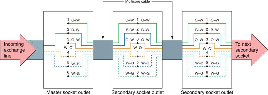
Figure 3.39 Telephone circuit outlet connection diagram.
An extension bell may be connected to the installation by connecting the two bell wires to terminals 3 and 5 of a telephone socket. The extension bell must be of the high impedance type having an REN rating. All equipment connected to a BT exchange line must display the green circle of approval.
The multi-core cable used for wiring extension socket outlets should be of a type intended for use with telephone circuits, which will normally be between 0.4 and 0.68 mm in cross-section. Telephone cable conductors are identified in Table 3.2 and the individual terminals in Table 3.3. The conductors should be connected as shown in Fig. 3.44. Telecommunications cables are Band I circuits and must be segregated from Band II circuits containing mains cables (IET Regulation 528.1).
Code |
Base colour |
Stripe |
|---|---|---|
G–W |
Green |
White |
B–W |
Blue |
White |
O–W |
Orange |
White |
W–O |
White |
Orange |
W–B |
White |
Blue |
W–G |
White |
Green |
Building management system
A building management system is a computer system that adjusts certain services within a building to meet the needs of the users. This means certain sensors are utilized in order to monitor certain key parameters such as temperature and thereafter the system programmer will use this information to vary and effect the amount of control required. Modern systems can control a number of buildings and therefore can be aligned to operate as efficiently as possible by being active during building occupancy.
Assessment criteria 1.4
Interpret sources of information relevant to planning of the installation of wiring systems and equipment (covered in Chapter 2 on pages 68 to 71)
Assessment criteria 1.5
Plan wiring system routes
Assessment criteria 1.6
Specify the positional requirements of wiring systems and equipment
Support and fixing methods for electrical equipment
It is vital that any wiring system must be planned properly in order to identify the optimum routes available. This also includes avoiding thermal insulation since it causes a de-rating effect – it reduces its current carrying capacity since due to the property of thermal insulation the wiring system will be exposed to higher temperatures. Other considerations involved in planning would be the distances required when drilling holes into wooden beams, for instance, so that load bearing structures are not weakened. The requirement is that there should be 300 mm laterally between holes and 50 mm from the hole to both the top and bottom of the joist. If those dimensions cannot be achieved then a different route must be taken.
Individual conductors may be installed in trunking or conduit and individual cables may be clipped directly to a surface or laid on a tray using the wiring system that is most appropriate for the particular installation. The installation method chosen will depend upon the contract specification, the fabric of the building and the type of installation – domestic, commercial or industrial. It is important that the wiring systems and fixing methods are appropriate for the particular type of installation and compatible with the structural materials used in the building construction. The support system must not be liable to premature collapse in the event of a fire as required by the 18th Edition of the Regulations in section 521.10. The electrical installation must be compatible with the installed conditions, and as has already been discussed when drilling into the fabric of the building, so as not to weaken load bearing girders or joists.
Key fact
Materials marked ‘CE’ are compliant with European Standards. BASEC approved cables comply with rigid manufacturing standards and specifications
The installation designer must consider the following questions:
• Does this wiring system meet the contract specification?
• Is the wiring system compatible with this particular installation?
• Do I need to consider any special regulations such as those required by agricultural and horticultural installations, swimming pools or flameproof installations?
• Will this type of electrical installation be aesthetically acceptable and compatible with the other structural materials?
The installation electrician must consider the following questions:
• Am I using materials and equipment that meet the relevant British Standards and the contract specification?
• Am I using an appropriate fixing method for this wiring system or piece of equipment?
• Will the structural material carry the extra load that my conduits and cables will place upon it?
• Will my fixings and fittings weaken the existing fabric of the building?
• Will the electrical installation interfere with other supplies and services?
• Will all terminations and joints be accessible upon completion of the erection period? (IET Regulations 513.1 and 526.3.)
• Will the materials being used for the electrical installation be compatible with the intended use of the building?
• Am I working safely and efficiently and in accordance with the IET Regulations (BS 7671)?
A domestic installation usually calls for a PVC insulated and sheathed wiring system. These cables are generally fixed using plastic clips incorporating a masonry nail, which means that the cables can be fixed to wood, plaster or brick with almost equal ease. However, the 3rd Amendment to the Regulations introduced a new Regulation 521.11.201 which requires wiring systems in escape routes be supported in such a manner that they will not prematurely collapse in the event of a fire.
The 18th Edition of the Regulations at 521.10.202 now requires the same fire proof support for all systems throughout the installation, not just escape routes.
However, it is only those wiring systems that might collapse before or during the period when the rescue services would enter a building, that require a fixing which will not collapse prematurely. So, cables installed in metal trunking, or conduit, or cables laid on top of cable tray or ladder rack will require no extra fixing considerations because they are adequately supported. Also, wiring systems fixed within the fabric of the building which is not liable to premature collapse in the event of a fire is safe in these circumstances.
It is the cable systems fixed with plastic clips or inside plastic trunking which will now require our consideration. These systems can fail when subject to either direct flame or the hot products of combustion leading to wiring systems hanging down and causing an entanglement risk as a result of the fire.
This makes it impossible for us to use non metallic cable clips, cable ties or plastic trunking as the only means of support for PVC wiring system. The regulation tells us that where non-metallic cable systems are used, a suitable means of fire resistant support and retention must be used to prevent cables falling down in the event of a fire. Note 4 to this Regulation advises that suitably spaced steel or copper clips, saddles or ties are examples which will meet this requirement. Cables must be run straight and neatly between clips fixed at equal distances which provide adequate support for the cable so that it does not become damaged by its own weight (IET Regulation 522.8.4), shown in Table 3.4 (page 162). A commercial or industrial installation might call for a conduit or trunking wiring system. A conduit is a tube, channel or pipe in which insulated conductors are contained. The conduit, in effect, replaces the PVC outer sheath of a cable, providing mechanical protection for the insulated conductors. A conduit installation can be rewired easily or altered at any time and this flexibility, coupled with mechanical protection, makes conduit installations popular for commercial and industrial applications. Steel conduits and trunking are, however, much heavier than single cables and, therefore, need substantial and firm fixings and supports. A wide range of support brackets is available for fixing conduit, trunking and tray installations to the fabric of a commercial or industrial installation. Some of these are shown in Fig. 3.40 and 3.48.
When a heavier or more robust fixing is required to support cabling or equipment, a nut and bolt or screw fixing is called for. Wood screws may be screwed directly into wood but when fixing to stone, brick or concrete it is first necessary to drill a hole in the masonry material which is then plugged with a material (usually plastic) to which a screw can be secured. For the most robust fixing to masonry materials, an expansion bolt such as that made by Rawlbolt should be used. For lightweight fixings to hollow partitions or plasterboard, a spring toggle can be used.
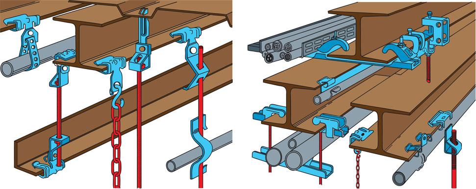
Figure 3.40 Some manufactured girder supports for electrical equipment.
Plasterboard cannot support a screw fixing directly into itself but the spring toggle spreads the load over a larger area, making the fixing suitable for light loads.
Let us look in a little more detail at individual joining, support and fixing methods.
Joining materials
Plastic can be joined with an appropriate solvent. Metal may be welded, brazed or soldered, but the most popular method of on-site joining of metal on electrical installations is by nuts and bolts or rivets.
A nut and bolt joint may be considered a temporary fastening since the parts can easily be separated if required by unscrewing the nut and removing the bolt. A rivet is a permanent fastening since the parts riveted together cannot be easily separated.
Two pieces of metal joined by a bolt and nut and by a machine screw and nut are shown in Fig. 3.41. The nut is tightened to secure the joint. When joining trunking or cable trays, a round-head machine screw should be used with the head inside to reduce the risk of damage to cables being drawn into the trunking or tray.
Thin sheet material such as trunking is often joined using a pop riveter. Special rivets are used with a hand tool, as shown in Fig. 3.42. Where possible, the parts to be riveted should be clamped and drilled together with a clearance hole for the rivet. The stem of the rivet is pushed into the nose bush of the riveter until the alloy sleeve of the rivet is flush with the nose bush (a). The rivet is then placed in the hole and the handles squeezed together (b). The alloy sleeve is compressed and the rivet stem will break off when the rivet is set and the joint complete (c). To release the broken-off stem piece, the nose bush is turned upward and the handles opened sharply. The stem will fall out and is discarded (d).
Bracket supports
Conduit and trunking may be fixed directly to a surface such as a brick wall or concrete ceiling, but where cable runs are across girders or other steel framework, spring steel clips may be used but support brackets or clips may require manufacturing.
The brackets are usually made from flat iron, which is painted after manufacturing to prevent corrosion. They may be made on-site by the electrician or, if many brackets are required, the electrical contractor may make a working sketch with dimensions and have the items manufactured by a blacksmith or metal fabricator.
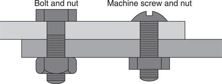
Figure 3.41 Joining of metal.
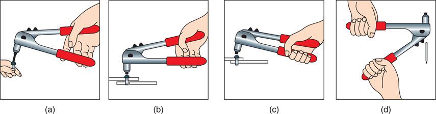
Figure 3.42 Metal joining with pop rivets.
The type of bracket required will be determined by the installation, but Fig. 3.43 gives some examples of brackets which may be modified to suit particular circumstances.
Fixing methods
PVC insulated and sheathed wiring systems are usually fixed with PVC clips in order to comply with IET Regulations 522.8.3 and 4. The clips are supplied in various sizes to hold the cable firmly, and the fixing nail is a hardened masonry nail. Figure 3.44 shows a cable clip of this type. The use of a masonry nail means that fixings to wood, plaster, brick or stone can be made with equal ease.
When heavier cables, trunking, conduit or luminaires have to be fixed, a screw fixing is often needed. Wood screws may be screwed directly into wood but when fixing to brick, stone, plaster or concrete it is necessary to drill a hole in the masonry material, which is then plugged with a material to which the screw can be secured.

Figure 3.43 Bracket supports for conduits and trunking.
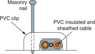
Figure 3.44 PVC insulated and sheathed cable clip.
Plastic plugs
A plastic plug is made of a hollow plastic tube split up to half its length to allow for expansion. Each size of plastic plug is colour coded to match a wood screw size.
Definition
A plastic plug Is made of a hollow plastic tube split up to half Its length to allow for expansion. Each size of plastic plug is colour coded to match a wood screw size.
A hole is drilled into the masonry, using a masonry drill of the same diameter, to the length of the plastic plug (see Fig. 3.45). The plastic plug is inserted into the hole and tapped home until it is level with the surface of the masonry. Finally, the fixing screw is driven into the plastic plug until it becomes tight and the fixture is secure.
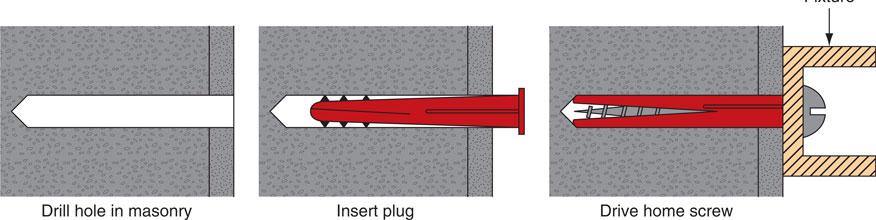
Figure 3.45 Screw fixing to plastic plug.
Expansion bolts
The most well-known expansion bolt is made by Rawlbolt and consists of a split iron shell held together by a steel ferrule at one end and a spring wire clip at the other end. Tightening the bolt draws up an expanding bolt inside the split iron shell, forcing the iron to expand and grip the masonry. Rawlbolts are for heavy-duty masonry fixings (see Fig. 3.46).
Definition
The most well-known expansion bolt is made by Rawlbolt and consists of a split iron shell held together by a steel ferrule at one end and a spring wire clip at the other end. Tightening the bolt draws up an expanding bolt inside the split iron shell, forcing the iron to expand and grip the masonry, Rawlbolts are for heavy-duty masonry fixings.
A hole is drilled in the masonry to take the iron shell and ferrule. The iron shell is inserted with the spring wire clip end first so that the ferrule is at the outer surface. The bolt is passed through the fixture, located in the expanding nut and tightened until the fixing becomes secure.
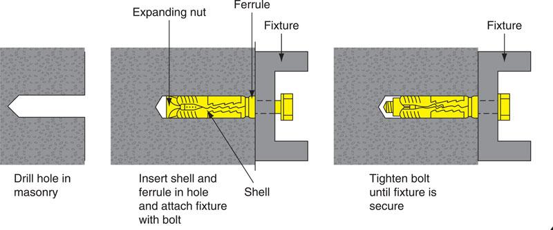
Figure 3.46 Expansion bolt fixing.
Spring toggle bolts
A spring toggle bolt provides one method of fixing to hollow partition walls which are usually faced with plasterboard and a plaster skimming. Plasterboard and plaster wall or ceiling surfaces are not strong enough to support a load fixed directly into the plasterboard, but the spring toggle spreads the load over a larger area, making the fixing suitable for light loads.
A hole is drilled through the plasterboard and into the cavity. The toggle bolt is passed through the fixture and the toggle wings screwed into the bolt. The toggle wings are compressed and passed through the hole in the plasterboard and into the cavity where they spring apart and rest on the cavity side of the plasterboard. The bolt is tightened until the fixing becomes firm. The bolt of the spring toggle cannot be removed after fixing without the loss of the toggle wings. If it becomes necessary to remove and refix the fixture a new toggle bolt will have to be used.
Given all that has been listed it is not surprising that the necessary skills can only be acquired through demonstration of the correct attitude and dedication to hone their craft through a NVQ Level 3 qualification in order to demonstrate the required understanding and proficiency to become a skilled person.
 Top tip
Inserting rawl plugs
When placing rawl plugs into masonry or tile surfaces, ensure the plug is pushed several millimetres past the surface.
Definition
A spring toggle bolt provides one method of fixing to hollow partition walls which are usually faced with plasterboard and a plaster skimming.
Definition
A skilled person is one who has the ability to perform a particular task properly.
Assessment criteria 1.7
Interpret the requirements of BS 7671 for the planned installation
Wiring systems and enclosures
The final choice of a wiring system must rest with those designing the installation in order to meet the installation criteria against the actual environment and the client’s wishes. But whatever system is employed, good workmanship by skilled or instructed persons and the use of proper materials is essential for compliance with the regulations (IET Regulation 134.1.1).
Most cables can be considered to be constructed in three parts: the conductor, which must be of a suitable cross-section to carry the load current; the insulation, which has a colour or number code for identification; and the outer sheath, which may contain some means of providing mechanical protection from impact damage. Some conductors are also given a PVC over-sheath in order to protect from corrosion when used outside.
The conductors of a cable are made of either copper or aluminium but aluminium only has approximately 61% of the conductivity of copper, which means that to carry the same current the aluminium conductor would have to be bigger. Given that it is lighter aluminium is used in overhead power transmission cables, which accounts for the fact that aluminium tends to be manufactured at sizes >16 mm.
Conductors can be stranded or solid. Solid conductors are only used in fixed wiring installations and tend to be shaped in larger cables such as 25 mm2. Stranded conductors are more flexible and conductor sizes from 4.0 to 25 mm2 contain seven strands. A 10 mm2 conductor, for example, has seven 1.35 mm diameter strands, which collectively make up the 10 mm2 cross-sectional area of the cable. Conductors above 25 mm2 have more than seven strands, depending upon the size of the cable. Flexible cords have multiple strands of very fine wire conductors, as fine as one strand of human hair. This gives the cable its very flexible quality.
New wiring colours
Over twenty-five years ago the United Kingdom agreed to adopt the European colour code for flexible cords, that is, brown for live or phase conductor, blue for the neutral conductor and green combined with yellow for earth conductors.
However, no similar harmonization was proposed for non-flexible cables used for fixed wiring. These were to remain as red for live or phase conductor, black for the neutral conductor and green combined with yellow for earth conductors.
On 31 March 2004, the IET published Amendment No. 2 to BS 7671: 2001, which specified new cable core colours for all fixed wiring in UK electrical installations.
These new core colours ‘harmonize’ the United Kingdom with the practice in mainland Europe.
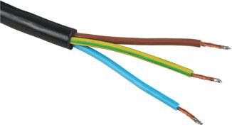
Figure 3.47 Brown is live or phase conductor, blue is neutral and green/yellow is earth.
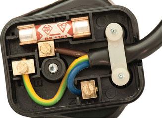
Figure 3.48 Electrical wires connected within a plug.
Fixed cable core colours up to 2006
• Single-phase supplies red line conductors, black neutral conductors, and green combined with yellow for earth conductors.
• Three-phase supplies red, yellow and blue line conductors, black neutral conductors and green combined with yellow for earth conductors.
These core colours could not be used after 31 March 2006.
New (harmonized) fixed cable core colours
• Single-phase supplies brown line conductors, blue neutral conductors and green combined with yellow are used for earth conductors (just like flexible cords).
• Three-phase supplies brown, black and grey line conductors, blue neutral conductors and green combined with yellow are used for earth conductors.
Top tip
Appendix K of the On-Site Guide identifies changes to cable core colour identification.
Cable core colours used from 31 March 2004 onwards
Extensions or alterations to existing single-phase installations do not require marking at the interface between the old and new fixed wiring colours. However, a warning notice must be fixed at the consumer unit or distribution fuse board which states:
Caution – this installation has wiring colours to two versions of BS 7671. Great care should be taken before undertaking extensions, alterations or repair that all conductors are correctly identified.
Alterations to three-phase installations must be marked at the interface L1, L2, L3 for the lines and N for the neutral. Both new and old cables must be marked.
These markings are preferred to coloured tape and a caution notice is again required at the distribution board. Appendix 7 of BS 7671: 2008 deals with harmonized cable core colours.
PVC insulated and sheathed cables
PVC which stands for polyvinylchloride is the common type of cable found in domestic and commercial installations. Because its inner insulation and outer sheath are made from thermoplastic it is known as PVC/PVC and this type of cable may be clipped direct to a surface or sunk in plaster. This type of cable is also used without a sheath and therefore becomes single-core thermoplastic or singles, when installed in conduit or trunking. It is the simplest and least expensive cable. Figure 3.50 shows a sketch of a twin and earth cable.
It is referred to in BS 7671 as ‘70°C thermoplastic insulated and sheathed flat cable with protective conductor’. This is in contrast to thermosetting, which can operate to an upper temperature range of 90°.
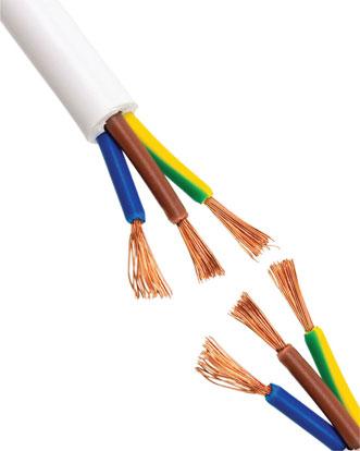
Figure 3.49 PVC, or polyvinylchloride, is commonly used in domestic and commercial installations.
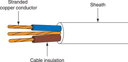
Figure 3.50 A twin and earth PVC insulated sheathed cable
Key fact
Single-core PVC cables must always be installed in protective enclosures and never clipped direct to a surface.
PVC/SWA cable
PVC insulated steel wire armour cables are used for wiring underground between buildings, for main supplies to dwellings, rising sub-mains and industrial installations. They are used where some mechanical protection of the cable conductors is required.
Definition
PVC/PVC, PVC flat profile and twin and earth are all different names for the same thermoplastic type cable.
The conductors are covered with colour-coded PVC insulation and then contained either singly or with others in a PVC sheath (see Fig. 3.51). Around this sheath is placed an armour protection of steel wires twisted along the length of the cable, and a final PVC sheath covering the steel wires protects them from corrosion. The armour sheath also provides the circuit protective conductor (CPC) and the cable is simply terminated using a compression gland.

Figure 3.51 A four-core PVC/SWA cable.
Safety first
• PVC cables should not be installed when the surrounding temperature is below 0°C.
• The PVC Insulation becomes brittle at low temperatures and may be damaged during Installation.
IET Regulation 522.1.2
Fire performance cables
There are two different types of cable on the market that have improved fire performance compared with standard cables. Those that react in a fire, give low smoke emission and reduced flame propagation, and those that are fire resistant, which will continue to operate during a fire when subjected to a specified flame source for a period of time.
Definition
BS 7671 specifies that the sounding element of a fire detection system must be installed using fire resistant cables.
Cables for fire alarm applications are now split into ‘standard’, where survival time of the cable is 30 minutes, and ‘enhanced’, where the survival time increases to 120 minutes.
Fixings, terminals and accessories must offer the same level of protection against fire as the cable you use.
Mineral insulated cable also known as Pyro and FP200 cable are the most commonly used examples of these cables.
Definition
Mineral insulated cable does not emit any smoke or toxic substances and does not allow any flame propagation.
MI cable
A mineral insulated (MI) cable has a seamless copper sheath, which makes it waterproof and fire- and corrosion-resistant. These characteristics often make it the only cable choice for hazardous or high-temperature installations such as oil refineries and chemical works, boiler houses and furnaces, petrol pump and fire alarm installations.
The cable has a small overall diameter when compared with alternative cables and may be supplied as bare copper or with a PVC over sheath. It is colour coded orange for general electrical wiring, white for emergency lighting or red for fire alarm wiring. The copper outer sheath provides the CPC, and the cable is terminated with a pot and sealed with compound and a compression gland (see Fig. 3.52).
The copper conductors are embedded in a white powder, magnesium oxide, which is non-ageing and non-combustible, but which is hygroscopic, which means that it readily absorbs moisture from the surrounding air, unless adequately terminated. The termination of an MI cable is a complicated process requiring the electrician to demonstrate a high level of practical skill and expertise for the termination to be successful.
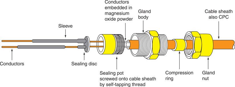
Figure 3.52 MI cable with terminating seal and gland.
Top tip
Mineral insulated cable must be properly sealed to avoid ingress of water especially since magnesium oxide is hygroscopic (absorbs water). Once assembled it is therefore good practice to check the glanding by testing its insulation resistance.
The marking on mineral insulated cables and accessories indicates the size and number of the conductors and its rating of light or heavy gauge. As an example, a mineral insulated cable sealing pot marked 3L1.5 would be constructed of 3 cores each of 1.5 mm2 c.s.a. and light gauge (up to 500 V). Heavy gauge cable is rated up to 750 V.
Key fact
Because of Its non-ageing property mineral Insulated cable Is used In listec buildings.
Definition
The difference between light and heavy gauge MI cable is that light gauge has a thinner outer copper sheath than heavy gauge.
FP 200 cable
FP 200 cable is similar in appearance to an MI cable in that it is a circular tube, or the shape of a pencil, and is available with a red or white sheath. However, it is much simpler to use and terminate than an MI cable.
The cable is available with either solid or stranded conductors that are insulated with ‘insudite’, a fire-resistant insulation material. The conductors are then screened by wrapping an aluminium tape around the insulated conductors, that is, between the insulated conductors and the outer sheath. This aluminium tape screen is applied metal side down and in contact with the bare CPC.
The sheath is circular and made of a robust thermoplastic low-smoke, zero halogen material.
FP 200 is available in 2, 3, 4, 7, 12 and 19 cores with a conductor size range from 1.0 to 4.0 mm2.
The cable is as easy to use as a PVC-insulated and sheathed cable. No special terminations are required; the cable may be terminated through a grommet into a knock-out box or terminated through a simple compression gland.
The cable is a fire-resistant cable, primarily intended for use in fire alarms and emergency lighting installations, or it may be embedded in plaster.
High-voltage overhead cables
Suspended from cable towers or pylons, overhead cables must be light, flexible and strong. The cable is constructed of stranded aluminium conductors formed around a core of steel-stranded conductors (see Fig. 3.53). The aluminium conductors carry the current and the steel core provides the tensile strength required to suspend the cable between pylons. The cable is not insulated since it is placed out of reach and insulation would only add to the weight of the cable.
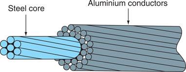
Figure 3.53 132 kV overhead cable construction.
Optical fibre cables
The introduction of fibre-optic cable systems and digital transmissions will undoubtedly affect future cabling arrangements and the work of the electrician.
Networks based on the digital technology currently being used so successfully by the telecommunications industry are very likely to become the long-term standard for computer systems. Fibre-optic systems dramatically reduce the number of cables required for control and communications systems, and this will in turn reduce the physical room required for these systems. Fibre-optic cables are also immune to electrical noise when run parallel to mains cables and, therefore, the present rules of segregation and screening may change in the future. There is no spark risk if the cable is accidentally cut and, therefore, such circuits are intrinsically safe. Intrinsic safety is described later under the heading ‘Working in hazardous areas’,Chapter 5.
Optical fibre cables are communication cables made from optical-quality plastic, the same material from which spectacle lenses are manufactured. The energy is transferred down the cable as digital pulses of laser light, as against current flowing down a copper conductor in electrical installation terms. The light pulses stay within the fibre-optic cable because of a scientific principle known as ‘total internal refraction’, which means that the laser light is actually bouncing along the cable by striking and deflecting off the inner wall as shown in Figure 3.43.
Definition
Optical fibre cables are communication cables made from optical-quality plastic, the same material from which spectacle lenses are manufactured. The energy is transferred down the cable as digital pulses of laser light, as against current flowing down a copper conductor in electrical installation terms.
The biggest advantage of fibre-optic cables is the speed with which they are able to transfer data. In 2014, researchers developed a new fibre optic technology capable of transferring data at a rate of 255 terabits per second (Tbps) – more data than the total traffic flowing across the internet at peak time. At such speeds, it is possible to transfer a 1 GB movie in 0.03 milliseconds, or a one terabyte file – 1000 GB of data – in just 0.03 seconds.
Commercial communication providers offer packages ranging from 300 MB/sec to 1 GB/sec so while this speed is not yet available to the public, the potential for huge development is there.
Definition
Fibre-optics operate on a process known as total internal reflection.
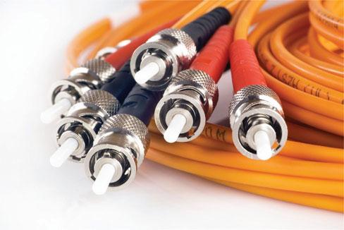
Figure 3.54 Optical fibre cable.

Figure 3.55 Cross-section of fibre-optic cable.
The cables are very small because the optical quality of the conductor is very high and signals can be transmitted over great distances. They are cheap to produce and lightweight because these new cables are made from high-quality plastic and not high-quality copper. Single-sheathed cables are often called ‘simplex’ cables and twin-sheathed cables ‘duplex’, that is, two simplex cables together in one sheath. Multi-core cables are available containing up to 24 single fibres.
Fibre-optic cables look like steel wire armour cables (but of course they are lighter) and should be installed in the same way, and given the same level of protection, as SWA cables. Avoid tight-radius bends if possible and kinks at all costs. Cables are terminated in special joint boxes that ensure cable ends are cleanly cut and butted together to ensure the continuity of the light pulses.
Top tip
Fibre optic cables still need to be handled with care and respect. Mishandling or installing an overly tight bending radius can damage its ability to transmit data.
Fibre-optic cables are Band I circuits when used for data transmission and must therefore be segregated from other mains cables to satisfy the IET Regulations.
The testing of fibre-optic cables requires special instruments to measure the light attenuation (i.e. light loss) down the cable. Finally, when working with fibre-optic cables, electricians should avoid direct eye contact with the low-energy laser light transmitted down the conductors.
Data cables
Category 5 cable (cat 5), cat 5e and cat 6 cables are twisted pair cables used for computer networks and carrying telephony and video signals. The cable consists of four pairs of conductors, twisted in pairs to minimize interference. It is usually terminated in punch down, insulation displacement connections to the RJ45 specification. The length of the data circuit is restricted to 100 m and is usually restricted to 90 m to allow for the length of the patch leads to be added.
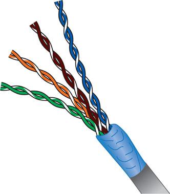
Figure 3.56 Data cables.
Temperature limits of cables
While there are many cable insulation materials, they are often divided into two types, thermoplastic or thermosetting. The current capacity of a cable is determined by the type of insulation as the build up of heat will have a detrimental effect on the insulation.
Thermoplastic materials are composed of chains of molecules (polyethylene for example). When heat is applied the energy will allow the bonds to separate and the material can flow (melt) and be reformed.
Thermosetting materials are formed when materials such as polyethylene undergo specific heating or chemical processes. During this process the individual chains become cross linked by smaller molecules making a rigid structure. Thermosetting materials cannot be melted or remoulded.
Due to the structure, thermosetting materials are generally more heat resistance and have greater strength.
BS 7671 gives current carrying capacities based on a maximum conductor temperature of:
• Thermoplastic 70°C
• Thermosetting 90°C
Definition
To offset any heat damage Butyl is a type of heat resistant cable that is used as the final connection to a water heater.
Choosing an appropriate wiring system
An electrical installation is made up of many different electrical circuits, lighting circuits, power circuits, single-phase domestic circuits and three-phase industrial or commercial circuits.
Whatever the type of circuit, the circuit conductors are contained within cables or enclosures.
Part 5 of the IET Regulations tells us that electrical equipment and materials must be chosen so that they are suitable for the installed conditions, taking into account temperature, the presence of water, corrosion, mechanical damage, vibration or exposure to solar radiation. Therefore, PVC insulated and sheathed cables are suitable for domestic installations but, for a cable requiring mechanical protection and suitable for burying underground, a PVC/SWA cable would be preferable. Category 5 cable (cat 5), cat 5e and cat 6 cables are twisted pair cables used for computer networks and carrying telephony and video signals as seen in Figure 3.56.
MI cables are waterproof, heatproof and corrosion-resistant with some mechanical protection. These qualities often make it the only cable choice for hazardous or high-temperature installations such as oil refineries, chemical works, boiler houses and petrol pump installations. An MI cable with terminating gland and seal is shown in Fig. 3.52.
The final choice of a wiring system must rest with those designing the installation and those ordering the work, but whatever system is employed, good workmanship by skilled or instructed persons and the use of proper materials is essential for compliance with the IET Regulations (IET Regulation 134.1.1). The necessary skills can be acquired by an electrical trainee who has the correct attitude and dedication to his craft.
PVC insulated and sheathed cable installations are used extensively for lighting and socket installations in domestic dwellings. Mechanical damage to the cable caused by impact, abrasion, penetration, compression or tension must be minimized during installation (IET Regulation 522.6.1). The cables are generally fixed using plastic clips incorporating a masonry nail, which means the cables can be fixed to wood, plaster or brick with almost equal ease. Cables should be run horizontally or vertically, not diagonally, down a wall. All kinks should be removed so that the cable is run straight and neatly between clips fixed at equal distances providing adequate support for the cable so that it does not become damaged by its own weight (IET Regulation 522.8.4 and Table D1 of the On-Site Guide). A Table of cable supports is shown in Table 3.4. Where cables are bent, the radius of the bend should not cause the conductors to be damaged (IET Regulation 522.8.3 and Table D5 of the On-Site Guide).
Cable supports to prevent the premature collapse of cables in the event of fire was introduced by the 3rd Amendment to the IET Regulations at 521.11.201 which requires wiring systems in escape routes to be supported in a manner that they will not prematurely collapse in the event of a fire.
Wiring systems which drop and hang across escape routes due to a failure of the means of support in fire conditions have the potential to entangle persons using the escape route including fire fighters entering the building to put out the fire.
The 18th Edition of the Regulations at 521.10.202 now requires the same fire proof support for all systems throughout the installation, not just escape routes. It is the cable systems fixed with plastic clips or inside plastic trunking which will now require our consideration. These systems can fail when subject to either direct flame or the hot products of combustion leading to wiring systems hanging down and causing an entanglement risk as a result of the fire.
This makes it impossible for us to use non metallic cable clips, cable ties or plastic trunking as the only means of support for PVC wiring system. The regulation tells us that where non-metallic cable systems are used, a suitable means of fire resistant support and retention must be used to prevent cables falling down in the event of a fire. Note 4 of the Regulation advises that suitably spaced steel or copper clips, saddles or ties are examples which will met this requirement.
In the future, if an electrical contractor carrying out an Electrical Installation Condition Report observes PVC cable systems supported only by non-metallic cable supports, they are to record a code C3 (Improvement Recommended) on the report.
Terminations or joints in the cable may be made in ceiling roses, junction boxes, or behind sockets or switches, provided that they are enclosed in a non-ignitable material, are properly insulated and are mechanically and electrically secure (IET Regulation 526). All joints must be accessible for inspection, testing and maintenance when the installation is completed (IET Regulation 526.3).
Top tip
Electrical connections and terminations need to be both electrically and mechanically sound
Where PVC insulated and sheathed cables are concealed in walls, floors or partitions, they must be provided with a box incorporating an earth terminal at each outlet position. PVC cables do not react chemically with plaster, as do some cables, and consequently PVC cables may be buried under plaster. Further protection by channel or conduit is only necessary if mechanical protection from nails or screws is required or to protect them from the plasterer’s trowel.
However, IET Regulation 522.6.202 now tells us that where PVC cables are to be embedded in a wall or partition at a depth of less than 50 mm they should be run along one of the permitted routes shown in Fig. 3.58. Figure 3.57 shows a typical PVC installation. To identify the most probable cable routes, IET Regulation 522.6.202 tells us that outside a zone formed by a 150 mm border all around a wall edge, cables can only be run horizontally or vertically to a point or accessory if they are contained in a substantial earthed enclosure, such as a conduit, which can withstand nail penetration, as shown in Fig. 3.58.
Where the accessory or cable is fixed to a wall that is less than 100 mm thick, protection must also be extended to the reverse side of the wall if a position can be determined.
Table 3.4 Spacing of cable supports

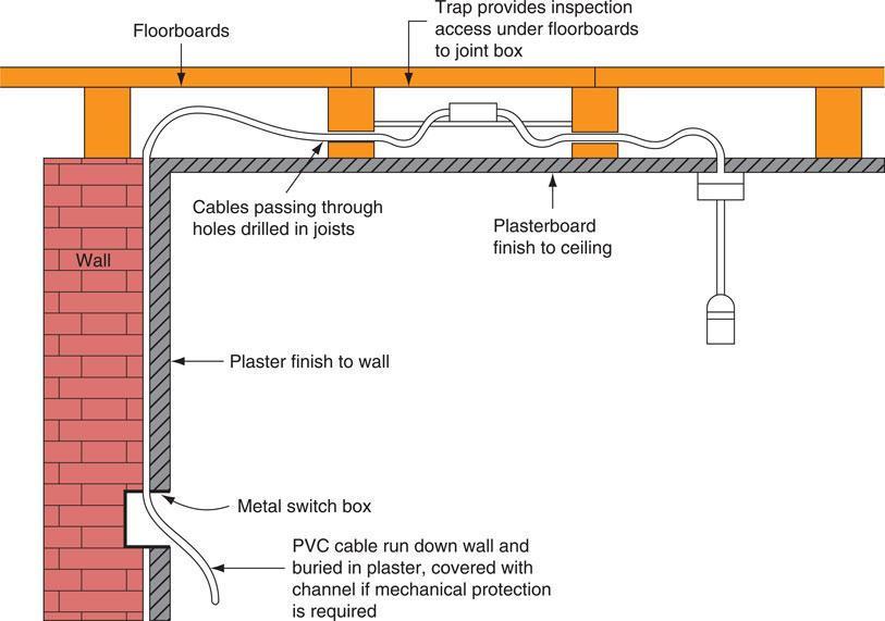
Figure 3.57 A concealed PVC sheathed wiring system.
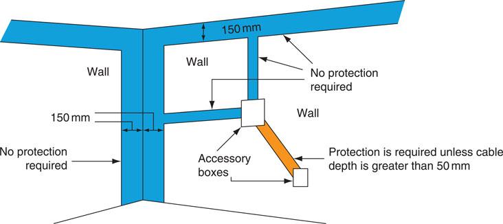
Figure 3.58 Permited cable routes.
Where none of this protection can be complied with the cable must be given additional protection with a 30 mA RCD (IET Regulation 522.6.202).
Where cables pass through walls, floors and ceilings the hole should be made good with incombustible material such as mortar or plaster to prevent the spread of fire (IET Regulations 527.1.2 and 527.2.1). Cables passing through metal boxes should be bushed with a rubber grommet to prevent abrasion of the cable.
Holes drilled in floor joists through which cables are run should be 50 mm below the top or 50 mm above the bottom of the joist to prevent damage to the cable by nail penetration (IET Regulation 522.6.201), as shown in Fig. 3.59. PVC cables should not be installed when the surrounding temperature is below 0°C or when the cable temperature has been below 0°C for the previous 24 hours because the insulation becomes brittle at low temperatures and may be damaged during installation.
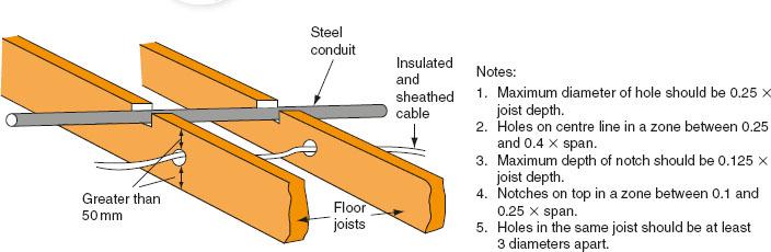
Figure 3.59 Correct installation of cables in floor joists.
 Try this
Definitions
In the margin write down a short definition of a ‘skilled or instructed person’.
Conduit installations
A conduit is a tube, channel or pipe in which insulated conductors are contained. The conduit, in effect, replaces the PVC outer sheath of a cable, providing mechanical protection for the insulated conductors. A conduit installation can be rewired easily or altered at any time, and this flexibility, coupled with mechanical protection, makes conduit installations popular for commercial and industrial applications. There are three types of conduit used in electrical installation work: steel, PVC and flexible.
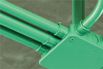
Figure 3.60 A conduit is a channel or pipe in which insulated conductors are contained.
Steel conduit
Steel conduits are made to a specification defined by BS 4568 and are either heavy gauge welded or solid drawn. Heavy gauge is made from a sheet of steel welded along the seam to form a tube and is used for most electrical installation work. Solid drawn conduit is a seamless tube, which is much more expensive and only used for special gas-tight, explosion-proof or flame proof installations.
Conduit is supplied in 3.75 m lengths and typical sizes are 16, 20, 25 and 32 mm. Conduit tubing and fittings are supplied in a black enamel finish for internal use or hot galvanized finish for use on external or damp installations. A wide range of fittings is available and the conduit is fixed using saddles or pipe hooks, as shown in Fig. 3.61.
Metal conduits are threaded with stocks and dies and bent using special bending machines. The metal conduit is also utilized as the CPC and, therefore, all connections must be screwed up tightly and all burrs removed so that cables will not be damaged as they are drawn into the conduit. Metal conduits containing a.c. circuits must contain phase and neutral conductors in the same conduit to prevent eddy currents from flowing, which would result in the metal conduit becoming hot (IET Regulations 521.5.1, 522.8.1 and 522.8.11).
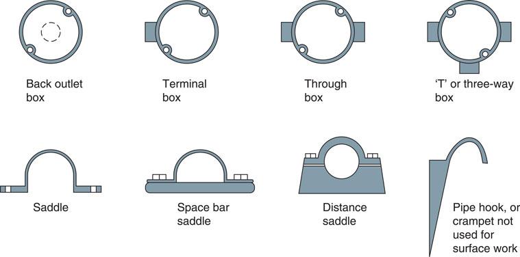
Figure 3.61 Conduit fitting and saddles.
PVC conduit
PVC conduit used on typical electrical installations is heavy gauge standard impact tube manufactured to BS 4607. The conduit size and range of fittings are the same as those available for metal conduit. PVC conduit is most often joined by placing the end of the conduit into the appropriate fitting and fixing with a PVC solvent adhesive. PVC conduit can be bent by hand using a bending spring of the same diameter as the inside of the conduit. The spring is pushed into the conduit to the point of the intended bend and the conduit then bent over the knee. The spring ensures that the conduit keeps its circular shape. In cold weather, a little warmth applied to the point of the intended bend often helps to achieve a more successful bend.
The advantages of a PVC conduit system are that it may be installed much more quickly than steel conduit and is non-corrosive, but it does not have the mechanical strength of steel conduit. Since PVC conduit is an insulator it cannot be used as the CPC and a separate earth conductor must be run to every outlet.
It is not suitable for installations subjected to temperatures below 25°C or above 60°C. Where luminaires are suspended from PVC conduit boxes, precautions must be taken to ensure that the lamp does not raise the box temperature or that the mass of the luminaire supported by each box does not exceed the maximum recommended by the manufacturer (IET Regulations 522.1 and 522.2). PVC conduit also expands much more than metal conduit and so long runs require an expansion coupling to allow for conduit movement and to help prevent distortion during temperature changes.
All conduit installations must be erected first before any wiring is installed (IET Regulation 522.8.2). The radius of all bends in conduit must not cause the cables to suffer damage, and therefore the minimum radius of bends given in Table D5 of the On-Site Guide applies (IET Regulation 522.8.3). All conduits should terminate in a box or fitting and meet the boxes or fittings at right-angles, as shown in Fig. 3.62. Any unused conduit-box entries should be blanked off and all boxes covered with a box lid, fitting or accessory to provide complete enclosure of the conduit system. Conduit runs should be separate from other services, unless intentionally bonded, to prevent arcing from occurring from a faulty circuit within the conduit, which might cause the pipe of another service to become punctured.
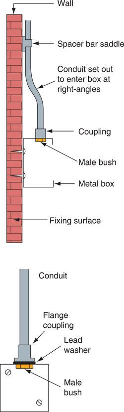
Figure 3.62 Terminating conduits.
Definition
Flexible conduit manufactured to BS 731-1: 1993 is made of interlinked metal spirals often covered with a PVC sleeving.
When drawing cables into conduit they must first be run off the cable drum. That is, the drum must be rotated as shown in Fig. 3.64 and not allowed to spiral off, which will cause the cable to twist.
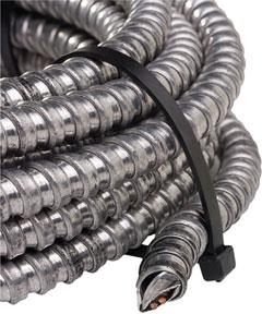
Figure 3.63 Flexible conduit is made up of interlinked metal spirals.
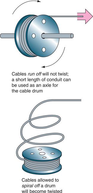
Figure 3.64 Running off cable from a drum.
Cables should be fed into the conduit in a manner that prevents any cable from crossing over and becoming twisted inside the conduit. The cable insulation must not be damaged on the metal edges of the draw-in box. Cables can be pulled in on a draw wire if the run is a long one. The draw wire itself may be drawn in on a fish tape, which is a thin spring steel or plastic tape.
A limit must be placed on the number of bends between boxes in a conduit run and the number of cables that may be drawn into a conduit to prevent the cables from being strained during wiring. Appendix E of the On-Site Guide gives a guide to the cable capacities of conduits and trunking.
Flexible conduit
Flexible conduit manufactured to BS 731-1: 1993 is made of interlinked metal spirals often covered with a PVC sleeving. The tubing must not be relied upon to provide a continuous earth path and, consequently, a separate CPC must be run either inside or outside the flexible tube (IET Regulation 543.2.7).
Definition
Flexible conduit manufactured to BS 731-1: 1993 is made of interlinked metal spirals often covered with a PVC sleeving.
Flexible conduit is used for the final connection to motors so that the vibrations of the motor are not transmitted throughout the electrical installation and to allow for modifications to be made to the final motor position and drive belt adjustments.
Definition
Single PVC insulated conductors are usually drawn into the installed conduit to complete the installation.
Conduit capacities
Single PVC insulated conductors are usually drawn into the installed conduit to complete the installation. Having decided upon the type, size and number of cables required for a final circuit, it is then necessary to select the appropriate size of conduit to accommodate those cables. The objective is to fill any enclosure such as conduit to a maximum of 45% conductor space, which means that the remaining 55% is left to air space. This reduces the cumulative heating effect.
The tables in Appendix E of the On-Site Guide describe a ‘factor system’ for determining the size of conduit required to enclose a number of conductors. The tables are shown in Tables 3.5 and 3.6 and use of these tables ensures that the 45% rule mentioned above is adhered to. The method is as follows:
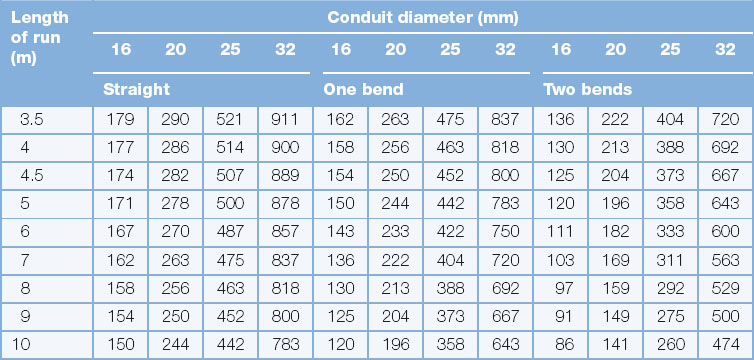
• Identify the cable factor for the particular size of conductor; see Table 3.5.
• Multiply the cable factor by the number of conductors, to give the sum of the cable factors.
• Identify the appropriate part of the conduit factor table given by the length of run and number of bends (see Table 3.6).
• The correct size of conduit to accommodate the cables is that conduit which has a factor equal to or greater than the sum of the cable factors.
Example 1
Six 2.5 mm2 PVC insulated cables are to be run in a conduit containing two bends between boxes 10 m apart. Determine the minimum size of conduit to contain these cables.
From Table 3.5:
From Table 3.5, a 25 mm conduit, 10 m long and containing two bends, has a factor of 260. A 20 mm conduit containing two bends only has a factor of 141 which is less than 180, the sum of the cable factors, and, therefore, 25 mm conduit is the minimum size to contain these cables.
Example 2
Ten 1.0 mm2 PVC insulated cables are to be drawn into a plastic conduit which is 6 m long between boxes and contains one bend. A 4.0 mm PVC insulated CPC is also included. Determine the minimum size of conduit to contain these conductors.
From Table 3.5:
From Table 3.5, a 20 mm conduit, 6 m long and containing one bend, has a factor of 233. A 16 mm conduit containing one bend only has a factor of 143 which is less than 203, the sum of the cable factors, and, therefore, 20 mm conduit is the minimum size to contain these cables.
Trunking installations
A trunking is an enclosure provided for the protection of cables that is normally square or rectangular in cross-section, having one removable side. Trunking may be thought of as a more accessible conduit system, and for industrial and commercial installations it is replacing the larger conduit sizes. A trunking system can have great flexibility when used in conjunction with conduit; the trunking forms the background or framework for the installation, with conduits running from the trunking to the point controlling the current-using apparatus. When an alteration or extension is required it is easy to drill a hole in the side of the trunking and run a conduit to the new point. The new wiring can then be drawn through the new conduit and the existing trunking to the supply point.
Key fact
Trunking is generally easier to install additional cables to an existing circuit in comparison with conduit. Access only requires the removal of the protective lid in comparison to having to draw in further cables.
Definition
A trunking is an enclosure provided for the protection of cables that is normally square or rectangular in cross-section, having one removable side. Trunking may be thought of as a more accessible conduit system.
Trunking is supplied in 3 m lengths and various cross-sections measured in millimetres from 50 × 50 up to 300 × 150. Most trunking is available in either steel or plastic.
Metallic trunking
Metallic trunking is formed from mild steel sheet, coated with grey or silver enamel paint for internal use or a hot-dipped galvanized coating where damp conditions might be encountered and made to a specification defined by BS EN 500 85. A wide range of accessories is available, such as 45° bends, 90° bends, tee and four-way junctions, for speedy on-site assembly. Alternatively, bends may be fabricated in lengths of trunking, as shown in Fig. 3.66. This may be necessary or more convenient if a bend or set is non-standard, but it does take more time to fabricate bends than merely to bolt on standard accessories.
Definition
Metallic trunking is formed from mild steel sheet, coated with grey or silver enamel paint for internal use or a hot-dipped galvanized coating where damp conditions might be encountered.
Insulated non-sheathed cables are permitted in a trunking system which provides at least the degree of protection IPXXD (which means total protection) or IP4X which means protection from a solid object greater than 1.0 mm such as a thin wire or strip. For site fabricated joints such as that shown in Fig 3.66, the installer must confirm that the completed item meets at least IPXXD (IET Regulation 521.10).
When fabricating bends the trunking should be supported with wooden blocks for sawing and filing, in order to prevent the sheet-steel from vibrating or becoming deformed. Fish-plates must be made and riveted or bolted to the trunking to form a solid and secure bend. When manufactured bends are used, the continuity of the earth path must be ensured across the joint by making all fixing screw connections very tight, or fitting a separate copper strap between the trunking and the standard bend. If an earth continuity test on the trunking is found to be unsatisfactory, an insulated CPC must be installed inside the trunking. The size of the protective conductor will be determined by the largest cable contained in the trunking, as described in Table 54.7 of the IET Regulations. If the circuit conductors are less than 16 mm2, then a 16 mm2 CPC will be required.
Non-metallic trunking
Trunking and trunking accessories are also available in high-impact PVC. The accessories are usually secured to the lengths of trunking with a PVC solvent adhesive. PVC trunking, like PVC conduit, is easy to install and is non-corrosive.
A separate CPC will need to be installed and non-metallic trunking may require more frequent fixings because it is less rigid than metallic trunking. All trunking fixings should use round-headed screws to prevent damage to cables since the thin sheet construction makes it impossible to countersink screw heads. The new fire proof support for non metallic cables systems must now be taken into consideration. See Choosing an Appropriate Wiring system earlier in this chapter.
Top tip
When sawing metals, conduit trunking or tray, a safe and effective speed is 50 strokes per minute.
Definition
Multi-compartment metallic trunking is used to segregate Band I and II cables as well as cabling associated with emergency systems.
Mini-trunking
Mini-trunking is very small PVC trunking, ideal for surface wiring in domestic and commercial installations such as offices. The trunking has a cross-section of 16 × 16 mm, 25 × 16 mm, 38 × 16 mm or 38 × 25 mm and is ideal for switch drops or for housing auxiliary circuits such as telephone or audio equipment wiring. The modern square look in switches and sockets is complemented by the mini-trunking, which is very easy to install (see Fig. 3.65).
Skirting trunking
Skirting trunking is a trunking manufactured from PVC or steel in the shape of a skirting board and is frequently used in commercial buildings such as hospitals, laboratories and offices. The trunking is fitted around the walls of a room at either the skirting board level or at the working surface level and contains the wiring for socket outlets and telephone points which are mounted on the lid, as shown in Fig. 3.65.
Definition
Skirting trunking is a trunking manufactured from PVC or steel in the shape of a skirting board and is frequently used in commercial buildings such as hospitals, laboratories and offices.
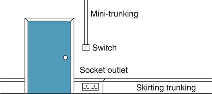
Figure 3.65 Typical installation of skirting trunking and mini-trunking.
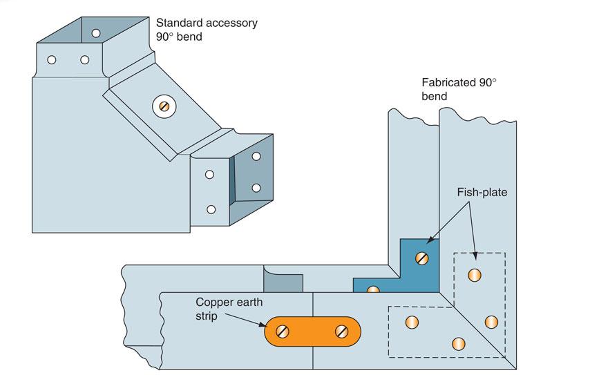
Figure 3.66 Alternative trunking bends.
Where any trunking passes through walls, partitions, ceilings or floors, short lengths of lid should be fitted so that the remainder of the lid may be removed later without difficulty. Any damage to the structure of the buildings must be made good with mortar, plaster or concrete in order to prevent the spread of fire.
Fire barriers must be fitted inside the trunking every 5 m, or at every floor level or room-dividing wall if this is a shorter distance, as shown in Fig. 3.67(a).
Where trunking is installed vertically, the installed conductors must be supported so that the maximum unsupported length of non-sheathed cable does not exceed 5 m. Figure 3.67(b) shows cables woven through insulated pin supports, which is one method of supporting vertical cables.
PVC insulated cables are usually drawn into an erected conduit installation or laid into an erected trunking installation. Table E4 of the On-Site Guide only gives factors for conduits up to 32 mm in diameter, which would indicate that conduits larger than this are not in frequent or common use. Where a cable enclosure greater than 32 mm is required because of the number or size of the conductors, it is generally more economical and convenient to use trunking.
Trunking capacities
The ratio of the space occupied by all the cables in a conduit or trunking to the whole space enclosed by the conduit or trunking is known as the space factor.
Definition
The ratio of the space occupied by all the cables in a conduit or trunking to the whole space enclosed by the conduit or trunking is known as the space factor.
Where sizes and types of cable and trunking are not covered by the tables in the On-Site Guide, a space factor of 45% must not be exceeded. This means that the cables must not fill more than 45% of the space enclosed by the trunking.
The tables take this factor into account.
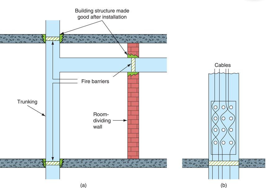
Figure 3.67 Installation of trunking (a) fire barriers in trunking, and (b) cable supports in vertical trunking.
To calculate the size of trunking required to enclose a number of cables:
• Identify the cable factor for the particular size of conductor (see Table 3.7).
• Multiply the cable factor by the number of conductors to give the sum of the cable factors.
• Consider the factors for trunking shown in Table 3.8. The correct size of trunking to accommodate the cables is trunking that has a factor equal to, or greater than, the sum of the cable factors.
Table 3.7 Trunking cable factors
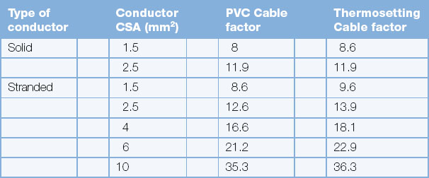
Example 3
Calculate the minimum size of trunking required to accommodate the following single-core PVC cables:
20 × 1.5 mm solid conductors
20 × 2.5 mm solid conductors
21 × 4.0 mm stranded conductors
16 × 6.0 mm stranded conductors
From Table 3.7, the cable factors are:
for 1.5 mm solid cable – 8.0
for 2.5 mm solid cable – 11.9
for 4.0 mm stranded cable – 16.6
for 6.0 mm stranded cable – 21.2
The sum of the cable terms is:
(20 × 8.0) + (20 × 11.9) + (21 × 16.6) + (16 × 21.2) + 1085.8. From Table 3.8, 75 × 38 mm trunking has a factor of 1146 and, therefore, the minimum size of trunking to accommodate these cables is 75 × 38 mm, although a larger size, say, 75 × 50 mm, would be equally acceptable if this was more readily available as a standard stock item.
Segregation of circuits
Where an installation comprises a mixture of low-voltage and very low-voltage circuits such as mains lighting and power, fire alarm and telecommunication circuits, they must be separated or segregated to prevent electrical contact (IET Regulation 528.1).
For the purpose of these regulations various circuits are identified by one of two bands as follows:
Band I: telephone, radio, bell, call and intruder alarm circuits, emergency circuits for fire alarm and emergency lighting.
Band II: mains voltage circuits.
When Band I circuits are insulated to the same voltage as Band II circuits, they may be drawn into the same compartment.
When trunking contains rigidly fixed metal barriers along its length, the same trunking may be used to enclose cables of the separate bands without further precautions, provided that each band is separated by a barrier, as shown in Fig. 3.68.

Figure 3.68 Segregation of cables in trunking.
Multi-compartment PVC trunking cannot provide band segregation since there is no metal screen between the bands. This can only be provided in PVC trunking if screened cables are drawn into the trunking.
Cable tray installations
Cable tray is a sheet-steel channel with multiple holes. The most common finish is hot-dipped galvanized but PVC-coated tray is also available. It is used extensively on large industrial and commercial installations for supporting MI and SWA cables that are laid on the cable tray and secured with cable ties through the tray holes.
Definition
Cable tray is a sheet-steel channel with multiple holes. The most common finish is hot-dipped galvanized, but PVC-coated tray is also available. It is used extensively on large industrial and commercial installations for supporting MI and SWA cables that are laid on the cable tray and secured with cable ties through the tray holes.
A cable tray should be adequately supported during installation by brackets that are appropriate for the particular installation. The tray should be bolted to the brackets with round-headed bolts and nuts, with the round head inside the tray so that cables drawn along the tray are not damaged.
The tray is supplied in standard widths from 50 to 900 mm, and a wide range of bends, tees and reducers is available. Fig. 3.69 shows a factory-made 90° bend at B. The tray can also be bent using a cable tray bending machine to create bends such as that shown at A in Fig. 3.69. The installed tray should be securely bolted with round-headed bolts where lengths or accessories are attached, so that there is a continuous earth path which may be bonded to an electrical earth. The whole tray should provide a firm support for the cables, and therefore the tray fixings must be capable of supporting the weight of both the tray and cables.
Definition
Cable basket is generally used to support data cables or emergency cables.
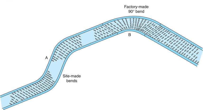
Figure 3.69 Cable tray with bends.
Cable basket installations
A cable basket is a form of cable tray made from a wire mesh material looking similar to a supermarket trolley. A basket is lighter than a tray and is generally used when there are numerous smaller, lighter cables that require a management system.
Cables are generally laid inside the basket rather than pulled in, allowing a quicker, more convenient installation.
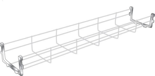
Figure 3.70 Cable basket.
A cable basket is much lighter than a tray and easier to install as well as being easier to carry out alterations to cabling after the installation due to the open nature of the basket.
Cable ladder
Cable ladder is at the other end of the scale to cable basket and is a heavy duty version of support, constructed as the name suggests to look like a ladder. Cable ladder is used to support heavier cables that do not need a continuous surface to be fixed to, but can span the spaces between the rungs. As these cables are usually high capacity cables, this type of support is usually used in industrial and large commercial installations.
Definition
Cable ladder tends to be used to support steel wire armour cables.
As the cables are capable of carrying high currents, large forces can be exerted on the cables, especially under fault conditions. Due to this, cable clamps are used to attach the cable to the ladder to ensure a sufficiently robust fixing.
Cable ducting
Within the electrical industry, underground cable routes often need to be reusable to allow for alterations in the installation. Heavy duty corrugated plastic pipes are installed to facilitate this rather than bury a cable directly into the ground.
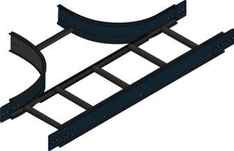
Figure 3.71 Cable ladder.
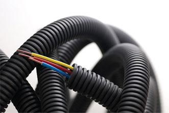
Figure 3.72 Heavy duty corrugated plastic pipes.

Figure 3.73 Cable ducting used in panel wiring.
Within control panels a form of trunking with multiple outlets like a comb is also known as ducting. The ducting allows routeing of the cabling while also containing it in a neat manner.
Modular wiring systems
Modular wiring systems are growing in popularity with designers and installers as a result of the reduction in installation times that can be up to 70% less than traditional methods. The idea of modular wiring is the provision of a factory manufactured and tested system that is fast to fit. The biggest benefit is the system can be manufactured off site in a quality controlled environment and supplied as a pluggable system, reducing onsite connections.
Definition
Modular wiring systems are known as plug and play, and save on installation times since they have already been fully tested.
Many large projects such as the Olympics have used modular construction techniques.
Busbar and power track systems
In an electrical system, a busbar is usually a flat uninsulated copper strip contained inside switchgear or panels for carrying high currents. The flat shape of the conductor gives a large surface area that allows for heat dissipation and for circuits to branch off along the length.
Definition
Busbar systems are used when high current usage is required. However, a disadvantage is that its many bolts and connections require maintenance tests to stay efficient.
Power track systems are similar to busbar systems in that they have conductors running through the containment and loads can be tapped off at multiple points. Whereas busbar systems are for high current distribution, power track systems are commonly used in offices under floors and similar installations feeding individual circuits such as socket outlets in floor boxes which provide flexibility for office reorganizations.
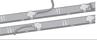
Figure 3.74 Power track system.
PVC/SWA cable installations
Steel wire armoured PVC insulated cables are now extensively used on industrial installations and often laid on cable tray. This type of installation has the advantage of flexibility, allowing modifications to be made speedily as the need arises. The cable has a steel wire armouring giving mechanical protection and permitting it to be laid directly in the ground or in ducts, or it may be fixed directly or laid on a cable tray. Figure 3.80 shows a PVC/SWA cable.
Definition
Steel wire armoured PVC insulated cables are now extensively used on industrial installations and often laid on cable tray.
It should be remembered that when several cables are grouped together the current rating will be reduced according to the correction factors given in Appendix 4 (Table 4C1) of the IET Regulations.
The cable is easy to handle during installation, is pliable and may be bent to a radius of eight times the cable diameter. The PVC insulation would be damaged if installed in ambient temperatures over 70°C or below 0°C, but once installed the cable can operate at low temperatures.
The cable is terminated with a simple gland that compresses a compression ring onto the steel wire armouring to provide the earth continuity between the switchgear and the cable.
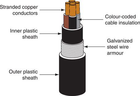
Figure 3.75 A four-core PVC/SWA cable.
MI cable installations
Mineral insulated cables are available for general wiring as:
• light-duty MI cables for voltages up to 600 V and sizes from 1.0 to 10 mm;
• heavy-duty MI cables for voltages up to 1000 V and sizes from 1.0 to 150 mm.
Figure 3.81 shows an MI cable and termination.
The cables are available with bare sheaths or with a PVC oversheath. The cable sheath provides sufficient mechanical protection for all but the most severe situations, where it may be necessary to fit a steel sheath or conduit over the cable to give extra protection, particularly near floor level in some industrial situations.
The cable may be laid directly in the ground, in ducts, on cable tray or clipped directly to a structure. It is not affected by water, oil or the cutting fluids used in engineering and can withstand very high temperatures or even fire. The cable diameter is small in relation to its current-carrying capacity and it should last indefinitely if correctly installed because it is made from inorganic materials.
These characteristics make the cable ideal for Band I emergency circuits, boiler houses, furnaces, petrol stations and chemical plant installations.
The cable is supplied in coils and should be run off during installation and not spiralled off, as described in Fig. 3.44 for conduit. The cable can be work hardened if over-handled or over-manipulated. This makes the copper outer sheath stiff and may result in fracture. The outer sheath of the cable must not be penetrated, otherwise moisture will enter the magnesium oxide insulation and lower its resistance. To reduce the risk of damage to the outer sheath during installation, cables should be straightened and formed by hammering with a hide hammer or a block of wood and a steel hammer. When bending MI cables the radius of the bend should not cause the cable to become damaged and clips should provide adequate support (IET Regulation 522.8.5); see Table D5 of the On-Site Guide.
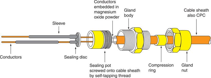
Figure 3.76 MI cable with terminating seal and gland.
The cable must be prepared for termination by removing the outer copper sheath to reveal the copper conductors. This can be achieved by using a rotary stripper tool or, if only a few cables are to be terminated, the outer sheath can be removed with side cutters, peeling off the cable in a similar way to peeling the skin from a piece of fruit with a knife. When enough conductor has been revealed, the outer sheath must be cut off square to facilitate the fitting of the sealing pot, and this can be done with a ringing tool. All excess magnesium oxide powder must be wiped from the conductors with a clean cloth. This is to prevent moisture from penetrating the seal by capillary action.
Cable ends must be terminated with a special seal to prevent the entry of moisture. Figure 3.76 shows a brass screw-on seal and gland assembly, which allows termination of the MI cables to standard switchgear and conduit fittings.
The sealing pot is filled with a sealing compound, which is pressed in from one side only to prevent air pockets from forming, and the pot closed by crimping home the sealing disc with an MI crimping tool.
Such an assembly is suitable for working temperatures up to 105°C. Other compounds or powdered glass can increase the working temperature up to 250°C.
The conductors are not identified during the manufacturing process and so it is necessary to identify them after the ends have been sealed. A simple continuity or polarity test, as described later in this chapter, can identify the conductors, which are then sleeved or identified with coloured markers.
Definition
Mineral-insulated seals are manufactured so that they can be matched to different explosive environments depending if the exposure is: continuous, likely or unlikely to occur.
Connection of MI cables can be made directly to motors, but to absorb the vibrations a 360° loop should be made in the cable just before the termination. If excessive vibration is expected, the MI cable should be terminated in a conduit through box and the final connection made by flexible conduit.
Copper MI cables may develop a green incrustation or patina on the surface, even when exposed to normal atmospheres. This is not harmful and should not be removed. However, if the cable is exposed to an environment that might encourage corrosion, an MI cable with an overall PVC sheath should be used.
Selecting the appropriate type of wiring system for the environment
Safety first
A reduced voltage system reduces the effect of an electric shock. BS 7671 specifies that all hand held equipment must be supplied through an 110 V supply. But even this is not enough protection for environments subjected to moisture which must be fed from SELV supplies.
Chapter 52 of BS 7671 places requirements on the designer to select the appropriate wiring system for the type of installation giving consideration to:
• cables and conductors;
• their connections, terminations and/or joints;
• their associated supports or suspensions; and
• their enclosures or methods of protection against external influences.
Appendix C of the On-Site Guide gives guidance on the application of cables for fixed wiring and flexible cables in Tables C1 and C2.
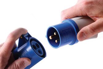
Figure 3.77 Industrial plugs are often referred to as ‘commando plugs’.
Industrial plugs, sockets and couplers
In 1968, the UK adopted the IEC 309 standard as BS 4343, and in 1999 replaced it with the European equivalent BS EN 60309.
Electricians often refer to these plugs as ‘commando plugs’ (refers to the MK Electric Company Commando range of connectors). The standard covers plugs, socket-outlets and couplers for industrial purposes.
IEC 60309-2 specifies a range of mains power connectors with circular housings, and different numbers and arrangements of pins for different applications. The 16 A single and three-phase variants are commonly used throughout Europe at campsites, marinas, workshops and farms. The colour of an IEC 60309 plug or socket indicates its voltage rating and the most common colours in use are yellow (110 V), blue (230 V) and red (400 V).
Cables to BS 7919: 2001 (2006)
Electric cables — Flexible cables for use with appliances and equipment intended for industrial and similar environments. Flexible cable, manufactured to BS 7919 Table 44 (not harmonized), commonly referred to as 3183A (Arctic Grade Flex), was specifically designed for use at 110 V a.c. from centre tapped transformers (55 V – 0 – 55 V).
The practice of using a 110 V centre tapped transformer is a UK practice, hence the lack of European harmonization of the standard.
The key feature of this cable is that it is designed to be suitable for installation and handling down to a temperature of −25°C, e.g. suitable for construction site installations.
As the standard applies to 110 V flexes only; strictly speaking, only a yellow flex should be referred to as an ‘Artic’ cable, however manufacturers supply other colours for other voltages such as blue for 230 V and often mark these as ‘Artic’ cables.
Terminating and connecting conductors
The entry of a cable end into an accessory, enclosure or piece of equipment is what we call a termination. Section 526 of the IET Regulations tells us that:
1 Every connection between conductors and equipment shall be durable, provide electrical continuity and mechanical strength and protection.
2 Every termination and joint in a live conductor shall be made within a suitable accessory, piece of equipment or enclosure that complies with the appropriate product standard.
3 Every connection shall be accessible for inspection, testing and maintenance.
4 The means of connection shall take account of the number and shape of the wires forming the conductor.
5 The connection shall take account of the cross-section of the conductor and the number of conductors to be connected.
6 The means of connection shall take account of the temperature attained in normal service.
7 There must be no mechanical strain on the conductor connections.
Definition
The entry of a cable end into an accessory, enclosure or piece of equipment is what we call a termination.
There is a wide range of suitable means of connecting conductors and we shall look at these in a moment. Whatever method is used to connect live conductors, the connection must be contained in an enclosed compartment such as an accessory; for example, a switch or socket box or a junction box. Alternatively, an equipment enclosure may be used; for example, a motor enclosure or an enclosure partly formed by non-combustible building material (IET Regulation 526.5). This is because faulty joints and terminations in live conductors can attain very high temperatures due to the effects of resistive heating. They might also emit arcs, sparks or hot particles with the consequent risk of fire or other harmful thermal effects to adjacent materials.
Types of terminal connection
Junction boxes
Junction boxes are probably the most popular method of making connections in domestic properties. Brass terminals are fixed inside a bakelite container. The two important factors to consider when choosing a junction box are the number of terminals required and the current rating. Socket outlet junction boxes have larger brass terminals than lighting junction boxes. See Fig. 3.78.
Key fact
Junction boxes are probably the most popular method of making connections in domestic properties.
Strip connectors
Strip connectors or a chocolate block is a very common method of connecting conductors. The connectors are mounted in a moulded plastic block in strips of 10 or 12. The conductors are inserted into the block and secured with the grub-screw. In order that the conductors do not become damaged, the screw connection must be firm but not overtightened. The size used should relate to the current rating of the circuit. Figure 3.84 shows a strip connector.
Key fact
Strip connectors or a chocolate block is a very common method of connecting conductors.
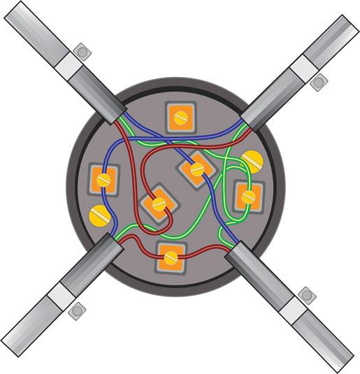
Figure 3.78 Standard junction boxes with screw terminals, junction box must be fixed and cables clamped.