CHAPTER 5
Unit QELTK3/007
Understanding the principles, practices and legislation for diagnosing and correcting electrical faults in electro technical systems and equipment in buildings, structures and the environment

Learning outcomes
When you have completed this chapter you should:
1. Understand the principles, regulatory requirements and procedures for completing the safe isolation of electrical circuits and complete electrical installations.
2. Understand how to complete the reporting and recording of electrical fault diagnosis and correction work.
3. Understand how to complete the preparatory work prior to fault diagnosis and correction work.
4. Understand the procedures and techniques for diagnosing electrical faults.
5. Understand the procedures and techniques for correcting electrical faults.
Note that Learning Outcomes 1.1–1.4 have been covered in QELTK3/006 but are again summarized above.
Requirements for safe working procedures
Assessment criteria 1.1 to 1.4 have already been covered in Chapter 4 but should be embraced alongside the following requirements. The following five safe working procedures must be applied before undertaking fault diagnosis:
1 The circuits must be isolated using a ‘safe isolation procedure’, such as that described in Fig 5.7.
2 All test equipment must be ‘approved’ and calibrated and connected to the test circuits by recommended test probes as described by the Health and Safety Executive (HSE) Guidance Note GS 38. The test equipment used must also be ‘proved’ on a known supply or by means of a proving unit such as that shown in Figure 4.2 and 4.4.
3 Isolation devices must be ‘secured’ in the ‘off’ position as shown in Figure 4.13. The key is retained by the person working on the isolated equipment.
4 Warning notices must be posted.
5 All relevant safety and functional tests must be completed before restoring the supply.
 Safety first
Undertaking fault diagnosis is inherently dangerous because there is a need to work on live supplies.
Assessment criteria 2.1
State the procedures for reporting and recording information on electrical fault diagnosis and correction work
Assessment criteria 2.2
State the procedures for informing relevant persons about information on electrical fault diagnosis and correction work and the completion of relevant documentation
Assessment criteria 2.3
Explain why it is important to provide relevant persons with information on fault diagnosis and correction work clearly, courteously and accurately
Recording faults
If an electrical installation fault is identified as a result of a periodic inspection for the purpose of completing an Electrical Installation Condition Report, then it should be documented as detailed in Appendix 6 of the IET Regulations.
The 18th Edition of the IET Regulations (2018) has introduced changes to the Periodic Inspection Report. This has now become the Electrical Installation Condition Report and incorporates changes to the classification coding system and a new inspection schedule that you will find in Appendix 6 of the IET Regulations. The inspection schedule for a domestic installation includes over 60 items that must be inspected and the electrician carrying out the inspection must comment on the condition of each item using the coding system described below. Commenting on the condition of items in relation to the code can also inform on the corrective process, for example whether an item can be repaired or justification on why it must be replaced and why further cost is necessary.
 Definition
The absence of circuit protective conductors would attract a C1 code, since it poses an immediate danger if a fault were to develop.
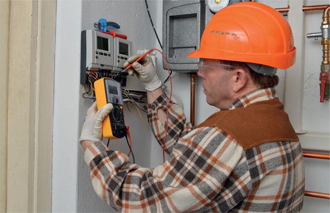
Figure 5.1 Undertaking fault finding is potentially hazardous since there is an expectation that you have to work with live supplies.
The objective in producing this new Electrical Installation Condition Report inspection schedule is to provide the electrician carrying out the inspection with guidelines, so that the inspection is done in a structured and consistent way and for the client to better understand the result of the inspection. The classification codes to be used on the condition report inspection schedule are shown below where green means ‘Good to Go’. Red means ‘Stop’ there is a problem here. Think of the colour code like traffic lights, and further investigation at a later date is a proceed with caution action.
✓ meaning an acceptable condition. The item inspected has been classified as acceptable.
C1 meaning an unacceptable condition. The item inspected has been classified as unacceptable. Immediate danger is present and the safety of those using the installation is at risk. For example, live parts are directly accessible.
Immediate remedial action is required.
C2 meaning an unacceptable condition. The item inspected has been classified as unacceptable. Potential danger is present and the safety of those using the installation may be at risk; for example, the absence of the main protective bonding conductors.
Urgent remedial action is required.
C3 meaning improvement is recommended. The item inspected is not dangerous for continued use but the inspector recommends that improvements be made. For example, the installation does not have RCDs installed for additional protection.
Improvements are recommended.
FI (further investigation) has uncovered a deficiency that was not possible to identify or uncover due to certain limitations or the actual extent of the inspection being carried out.
Let us assume that while carrying out a visual inspection, the electrician observes a badly damaged socket outlet. On close inspection he realizes that it is possible to touch a live part through the cracked plate. This fault will attract a C1 code because there is immediate danger. Alternatively, if on close inspection the electrician realizes it is possible to touch an earth connection, then it will attract a C2 code: there is potential danger here because the earth wire may become live under fault conditions.
Definition
The absence of equipotential bonding conductors would attract a C2 code, since there is potential danger of dangerous voltage developing.
The presence of a C1 or C2 code will result in the overall condition of the electrical installation being reported as unsatisfactory – it has failed to meet the standard. The inspector should report the findings to the duty holder or person responsible for the installation immediately, both verbally and in writing, that a risk of injury exists. If possible, immediately dangerous situations, given a C1 code, should be made safe, isolated or rectified on discovery.
A code C3 in itself would not warrant an unsatisfactory result. It is simply stating that while the installation is not compliant with the latest edition of the IET Regulations, it is compliant with a previous edition, and the item is not unsafe and does not necessarily require upgrading. This differs from when an inspection has revealed a deficiency or non-compliance that could not be fully identified due to the extent or limitations of the inspection. An FI should be recorded if any further investigation is liable to uncover and lead to a classification code C1 (danger present) or C2 (potentially dangerous) but should not be recorded if it is thought that any investigation would lead, at worst, to a C3 classification.
Definition
Electrical Installation Condition Reports are used to report on the condition of existing installations.
• N/V meaning not verified. Although a particular item on the schedule is relevant to the installation, the inspector was unable to verify its condition.
• LIM meaning limitation. A particular item on the schedule is relevant to the installation but there were certain limitations in being able to check the condition.
• N/A meaning not applicable. The particular item on the schedule is not relevant to the installation being inspected.
The Electrical Installation Condition Report should only be used for an existing building. The report should include:
• schedules of both the inspection and test results in section A;
• the reasons for producing the report such as a change of occupancy or landlord’s maintenance should be identified in section B;
• the extent and limitations of the report should be stated in section D;
• the inspector producing the final report should give a summary of the condition of the installation in terms of the safety of the installation in section E, stating how any C1, C2, C3 and F1 codes given for items in the schedule, may affect the overall condition of the installation being classified as unsatisfactory;
• the recommended date of the next Electrical Installation Condition Report should be given in section F.
Further information on the new coding system can be downloaded free from the Electricity Safety Council’s Best Practice Guide 4.
Assessment criteria 3.1
Specify safe working procedures that should be adopted for completion of fault diagnosis and correction work
Carrying out a safe isolation procedure is only one element in ensuring that any work activities involving fault diagnosis are sound, logical and safe. For instance, given that it might be necessary for the supply to be live when tracing down faults, priority should be given to the positioning of notices and barriers to physically restrict access to unauthorized personnel. The notices involved need to be positioned in view of all routes to the point of isolation and work. Not only must signage contribute to effective communication but all technical personnel involved must be informed of the fault-finding process taking place, and equally important, informing those who might be affected by such activities.
Assessment criteria 3.2
Interpret and apply the logical stages of fault diagnosis and correction work that should be followed
Assessment criteria 3.3
Identify and describe common symptoms of electrical faults
Assessment criteria 3.4
State the causes of different types of fault
Fault diagnosis
To diagnose and find faults in electrical installations and equipment is probably one of the most difficult tasks undertaken by an electrician. The knowledge of fault finding and the diagnosis of faults can never be completely ‘learned’ because no two fault situations are exactly the same. As the systems we install become more complex, then the faults developed on these systems become more complicated to solve. To be successful the individual must have a thorough knowledge of the installation or piece of equipment and have a broad range of the skills and competences associated with the electrical industries. The ideal person will tackle the problem using a reasoned and logical approach, recognize his own limitations and seek help and guidance where necessary.
 Key fact
Fault ti nding involves understanding the systems in use, using a logical and reasoned approach and communicating when supplies are to be shut off or re-applied.
The tests recommended by the IET Regulations can be used as a diagnostic tool but the safe working practices described by the Electricity at Work Regulations and elsewhere must always be observed during the fault-finding procedures.
If possible, fault finding should be planned ahead to avoid inconvenience to other workers and to avoid disruption of the normal working routine. However, a faulty piece of equipment or a fault in the installation is not normally a planned event and usually occurs at the most inconvenient time. The diagnosis and rectification of a fault is therefore often carried out in very stressful circumstances.
Symptoms of an electrical fault
The basic symptoms of an electrical fault may be described in one or a combination of the following ways:
1 There is a complete loss of power.
2 There is partial or localized loss of power.
3 The installation or piece of equipment is failing because of the following:
– an individual component is failing;
– the whole plant or piece of equipment is failing;
– the insulation resistance is low;
– the overload or protective devices operate frequently;
– electromagnetic relays will not latch, giving an indication of undervoltage.
 Top tip
Fault finding should be a systematic process aligning specific indicators and a circuit’s behaviour in order to determine a cause of action. A circuit breaker tripping is normally an indication of excess current (short circuit conditions).
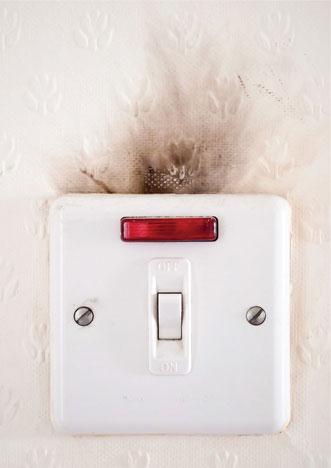
Figure 5.2 Symptoms aren’t always as obvious as this.
Causes of electrical faults
A fault is not a natural occurrence; it is an unplanned event that occurs unexpectedly. The fault in an electrical installation or piece of equipment may be caused by:
• negligence – that is, lack of proper care and attention;
• misuse – that is, not using the equipment properly or correctly;
• abuse – that is, deliberate ill treatment of the equipment.
If the installation was properly designed in the first instance to perform the tasks required of it by the user, then the negligence, misuse or abuse must be the fault of the user. However, if the installation does not perform the tasks required of it by the user, then the negligence is due to the electrical contractor not designing the installation to meet the needs of the user.
Definition
A fault is not a natural occurrence; it is an unplanned event that occurs unexpectedly,
Negligence on the part of the user may be due to insufficient maintenance or lack of general care and attention, such as not repairing broken equipment or removing covers or enclosures that were designed to prevent the ingress of dust or moisture.
Misuse of an installation or piece of equipment may occur because the installation is being asked to do more than it was originally designed to do, because of the expansion of a company, for example. Circuits are sometimes overloaded because a company grows and a greater demand is placed on the existing installation by the introduction of new or additional machinery and equipment that is otherwise healthy. All electrical connections should be both electrically and mechanically sound, but often bad workmanship or inappropriate or non-precision tooling can cause high resistance joints, which can lead to not only volt drop issues but more seriously in electrical fires. Other faults such as transient voltages can be generated by relays and contactors which cause transient spikes which can be specially damaging to electronic equipment.
The 18th Edition of the IET Regulations at 532.6 and 421.1.7 has introduced a new topic, Arc Fault Detection Devices. (AFDD) These are compulsory in the EU Countries but only recommended in this country by the IET and the British standards. They are recognised as giving additional protection against fires caused by arc faults. Arc faults can be formed by cable insulation defects, damage to cables by impact or penetration by nails and screws, and loose terminal connections. AFDDs detect faults which MCBs and RCDs cannot detect. They are installed at the origin of the final circuit to be protected.
Before an electrician can begin to diagnose the cause of a fault he must:
• have a thorough knowledge and understanding of the electrical installation or electrical equipment;
• collect information about the fault and the events occurring at or about the time of the fault from the people who were in the area at the time;
• begin to predict the probable cause of the fault using his own and other people’s skills and expertise;
• test some of the predictions using a logical approach to identify the cause of the fault.
Most importantly, electricians must use their detailed knowledge of electrical circuits and equipment learned through training and experience and then apply this knowledge to look for a solution to the fault.
Requirements for successful electrical fault finding
The steps involved in successfully finding a fault can be summarized as follows:
1 Gather information by talking to people and looking at relevant sources of information such as manufacturer’s data, circuit diagrams, charts and schedules.
2 Analyse the evidence and use standard tests and a visual inspection to predict the cause of the fault.
3 Interpret test results and diagnose the cause of the fault.
4 Rectify the fault.
5 Carry out functional tests to verify that the installation or piece of equipment is working correctly and that the fault has been rectified.
Key fact
Fault ti nding can be broken down into: who, where, when and why?
Designing out faults
The designer of the installation cannot entirely design out the possibility of a fault occurring but he can design in ‘damage limitation’ should a fault occur. For example, designing in two, three or four lighting and power circuits will reduce the damaging effect of any one circuit failing because not all lighting and power will be lost as a result of a fault. Limiting faults to only one of many circuits is good practice because it limits the disruption caused by a fault. IET Regulation 314 tells us to divide an installation into circuits as necessary so as to:
1 avoid danger and minimize inconvenience in the event of a fault occurring;
2 facilitate safe operation, inspection, testing and maintenance;
3 reduce unwanted RCD tripping, sometimes called ‘nuisance tripping’.

Figure 5.3 Circuits are divided to avoid danger, inconvenience and reduce unwanted tripping of RCDs.
Assessment criteria 3.5
Specify the types of faults and their likely locations
Where do electrical faults occur?
1 Faults occur in wiring systems, but not usually along the length of the cable, unless it has been damaged by a recent event such as an object being driven through it or a JCB digger pulling up an underground cable. Cable faults usually occur at each end, where the human hand has been at work at the point of cable interconnections. This might result in broken conductors, trapped conductors or loose connections in joint boxes, accessories or luminaires. All cable connections must be made mechanically and electrically secure. They must also remain accessible for future inspection, testing and maintenance (IET Regulation 526.3). The only exceptions to this rule are when:
Definition
All terminations and connections need to be both mechanically and electrically secure. Badly formed joints are a prime cause of electrical fires.
• underground cables are connected in a compound-filled or encapsulated joint;
• floor-warming or ceiling-warming heating systems are connected to a cold tail;
• a joint is made by welding, brazing, soldering or a compression tool;
• a joint is made in a maintenance free accessory complying with BS 5733 and marked with the symbol MF, as shown in Fig. 3.85 of Chapter 3.
Since they are accessible, cable interconnections are an obvious point of investigation when searching out the cause of a fault.
Key fact
A prime cause of electrical fires stems from badly formed electrical connections.
2 Faults also occur at cable terminations. The IET Regulations require that a cable termination of any kind must securely anchor all conductors to reduce mechanical stresses on the terminal connections. All conductors of flexible cords must be terminated within the terminal connection, otherwise the current-carrying capacity of the conductor is reduced, which may cause local heating. Flexible cords and fine multiwire conductors are delicate – has the terminal screw been over-tightened, thus breaking the connection as the conductors flex or vibrate? Cables and flexible cords must be suitable for the temperature to be encountered at the point of termination or must be provided with additional insulation sleeves to make them suitable for the surrounding temperatures (IET Regulations 522.2 and 526.9). Even mineral insulated cable, which is robust in design, is sometimes used with a PVC over-sheath to protect from corrosion.
3 Faults also occur at accessories such as switches, sockets, control gear, motor contactors either when they enter or at the point of connection with electronic equipment. The source of a possible fault is again at the point of human contact with the electrical system and again the connections must be checked as described in the first two points above as well as ensuring grommets are fitted where needed. Contacts that make and break a circuit are another source of wear and possible failure, so switches and motor contactors may fail after extensive use. For instance, relay or contactor contacts can weld shut, thus causing a short circuit, or can partially close, causing a high resistance, or even fail to close altogether, causing an open circuit fault. Socket outlets that have been used extensively and loaded to capacity, in say kitchens, are another source of fault due to overheating or loose connections. Electronic equipment can be damaged by the standard tests described in the IET Regulations and must, therefore, be disconnected before testing begins.
Key fact
Equipment that is not designed or appropriate to their environment can suffer premature failure.
4 Faults occur on instrumentation panels either as a result of a faulty instrument or as a result of a faulty monitoring probe connected to the instrument. Many panel instruments are standard sizes connected to CTs or VTs and this is another source of possible faults of the types described in points 1–3.
5 Faults occur in protective devices for the reasons given in points 1–3 above but also because they may have been badly selected for the job in hand and do not offer adequate protection, discrimination or selectivity as described in Chapter 3 of this book.
Key fact
If conductor strands are damaged during the termination process the conductor has effectively become smaller, reducing its current-carrying capacity.
6 Faults often occur in luminaires (light fittings) because the lamp has expired. Discharge lighting (fluorescent fittings) also requires a ‘starter’ to be in good condition, although many fluorescent luminaires these days use starter-less electronic control gear. The points made in 1–3 about cable and flexible cord connections are also relevant to luminaire faults.
7 Faults occur when terminating flexible cords and fine multiwire conductors as a result of the flexible cable being of a smaller cross-section than the load demands, because it is not adequately anchored to reduce mechanical stresses on the connection or because the flexible cord is not suitable for the ambient temperature to be encountered at the point of connection. When terminating flexible cords, the insulation should be carefully removed without cutting out any flexible cord strands of wire because this effectively reduces the cross-section of the conductor. The conductor strands should be twisted together and then doubled over, if possible, and terminated in the appropriate connection as shown in Fig. 3.84. The connection screws should be opened fully so that they will not snag the flexible cord as it is eased into the connection. The insulation should go up to, but not into, the termination. The terminal screws should then be tightened. When terminating very fine conductors, see also IET Regulation 526.9.
Key fact
Doubling over conductor strands increases the contact area of the conductor termination which lowers its contact resistance.

Figure 5.4 It is essential that any test equipment used in fault finding is appropriate, calibrated and maintained in a good condition.
8 Faults occur in electrical components, equipment and accessories such as motors, starters, switch gear, control gear, distribution panels, switches, sockets and luminaires because these all have points at which electrical connections are made. It is unusual for an electrical component to become faulty when it is relatively new because it will have been manufactured and tested to comply with the appropriate British Standard, however it is not unknown.
Key fact
Whatever method is used to make the connection in conductors, the correction must be both electrically and mechanically sound if we are to avoid high resistance joints, corrosion and erosion at the point of termination.
Through overuse or misuse, components and equipment do become faulty, but most faults are caused by poor installation techniques or design. Ingress of moisture into an enclosure will be largely due to inadequate IP requirements. When re-terminating a connection care must be taken to use the same size and type of termination. This is because using an aluminium crimp with a copper conductor can actually introduce dissimilar metal corrosion.
Overall, however, modern electrical installations using new materials can now last longer than 50 years. Therefore, they must be properly installed. Good design, good workmanship and the use of proper materials are essential if the installation is to comply with the relevant regulations (IET Regulations 133.1 to 134.1).
Safety first
Cable fault
Faults do occur in wiring systems but not usually along the cable length. Faults usually occur at each end where the human hand has been at work making connections.
Assessment criteria 3.6
State the special precautions that should be taken
Special situations or hazardous electrical locations
All electrical installations and installed equipment must be safe to use and free from the dangers of electric shock, but some installations or locations require special consideration because of the inherent dangers of the installed conditions. The danger may arise because of the corrosive or explosive nature of the atmosphere, because the installation must be used in damp or low-temperature conditions or because there is a need to provide additional mechanical protection for the electrical system. Part 7 of the IET Regulations deals with these special installations or locations. In this section we will consider some of the installations that require special consideration.
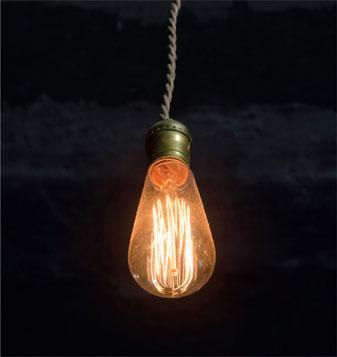
Figure 5.5 Exicessive lengths of cable or high resistance connections can generate volt drop issues, which in turn can result in lights appearing dim.
Safety first
Working alone
Never work in:
• confined spaces
• storage tanks
• enclosed ductwork.
Working alone
Some working situations are so potentially hazardous that not only must PPE be worn, but you must also never work alone and safe working procedures must be in place before your work begins to reduce the risk. It is unsafe to work in isolation in the following situations:
• when working above ground;
• when working below ground;
• when working in confined spaces;
• when working close to unguarded machinery;
• when a fire risk exists;
• when working close to toxic or corrosive substances such as battery acid.
Safety first
When working within hazardous environments one way of incorporating a safe system of work is to use a permit to work, which will control access.
Permit-to-work system
The permit-to-work procedure is a type of ‘safe system to work’ procedure used in specialized and potentially dangerous plant process situations. The procedure was developed for the chemical industry, but the principle is equally applicable to the management of complex risk in other industries or situations. For example:
• working on part of an assembly line process where goods move through a complex, continuous process from one machine to another (e.g. the food industry);
• repairs to railway tracks, tippers and conveyors;
• working in confined spaces (e.g. vats and storage containers);
• working on or near overhead crane tracks;
• working underground or in deep trenches;
• working on pipelines;
• working near live equipment or unguarded machinery;
• roof work;
• working in hazardous atmospheres (e.g. the petroleum industry);
• working near or with corrosive or toxic substances.
Definition
Permit to work is a type of ‘safe system to work’ procedure used in specialized and potentially dangerous plant process situations.
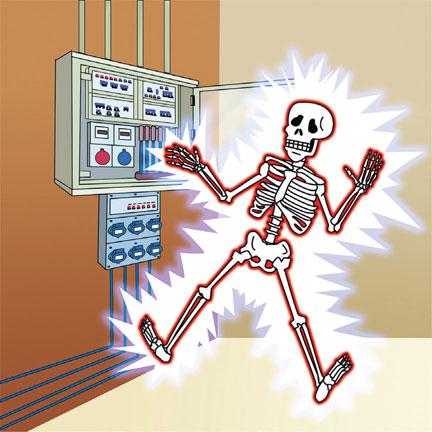
Figure 5.6 Some places are more dangerous than others, but if there is always the danger of an electric shock.
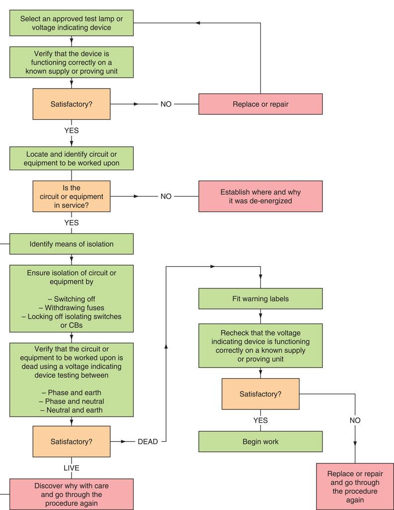
Figure 5.7 Flowchart or method statement for a secure isolation procedure.
All the above situations are high-risk working situations that should be avoided unless you have received special training and will probably require the completion of a permit to work. Permits to work must adhere to the following eight principles:
1 Wherever possible the hazard should be eliminated so that the work can be done safely without a permit to work.
2 The site manager has overall responsibility for the permit to work even though he may delegate the responsibility for its issue.
3 The permit must be recognized as the master instruction, which, until it is cancelled, overrides all other instructions.
4 The permit applies to everyone on-site, other trades and subcontractors.
5 The permit must give detailed information, for example: (i) which piece of plant has been isolated and the steps by which this has been achieved; (ii) what work is to be carried out; (iii) the time at which the permit comes into effect.
6 The permit remains in force until the work is completed and is cancelled by the person who issued it.
7 No other work is authorized. If the planned work must be changed, the existing permit must be cancelled and a new one issued.
8 Responsibility for the plant must be clearly defined at all stages because the equipment that is taken out of service is released to those who are to carry out the work.
The people doing the work, the people to whom the permit is given, take on the responsibility of following and maintaining the safeguards set out in the permit, which will define what is to be done (no other work is permitted) and the time scale in which it is to be carried out. The permit-to-work system must help communication between everyone involved in the process or type of work. Employers must train staff in the use of such permits and, ideally, training should be designed by the company issuing the permit, so that sufficient emphasis can be given to particular hazards present and the precautions which will be required to be taken. For further details see Permit to Work @www.hse.gov.uk.
Working in hazardous areas
The British Standards concerned with hazardous areas were first published in the 1920s and were concerned with the connection of electrical apparatus in the mining industry. Since those early days many national and international standards, as well as codes of practice, have been published to inform the manufacture, installation and maintenance of electrical equipment in all hazardous areas. The relevant British Standards for Electrical Apparatus for Potentially Explosive Atmospheres are BS 5345, BS EN 60079 and BS EN 50014: 1998. They define a hazardous area as ‘any place in which an explosive atmosphere may occur in such quantity as to require special precautions to protect the safety of workers’. Clearly these regulations affect the petroleum industry, but they also apply to petrol filling stations.
Definition
The British Standards def ne a hazardous area as ‘any place in which an explosive atmosphere may occur in such quantity as to require special precautions to protect the safety of workers’.
Most flammable liquids only form an explosive mixture between certain concentration limits. Above and below this level of concentration the mix will not explode. The lowest temperature at which sufficient vapour is given off from a flammable substance to form an explosive gas–air mixture is called the flashpoint. A liquid that is safe at normal temperatures will require special consideration if heated to flashpoint. An area in which an explosive gas–air mixture is present is called a hazardous area, as defined by the British Standards, and any electrical apparatus or equipment within a hazardous area must be classified as flameproof.
Definition
The lowest temperature at which sufficient vapour is given off from a flammable substance to form an explosive gas-air mixture is called the flashpoint.
Flameproof electrical equipment is constructed so that it can withstand an internal explosion of the gas for which it is certified, and prevent any spark or flame resulting from that explosion leaking out and igniting the surrounding atmosphere. This is achieved by manufacturing flameproof equipment to a robust standard of construction. All access and connection points have wide machined flanges that damp the flame in its passage across the flange. Flanged surfaces are firmly bolted together with many recessed bolts, as shown in Fig. 5.8. Wiring systems within a hazardous area must comply with flameproof fittings using an appropriate method, such as:
• PVC cables encased in solid drawn heavy-gauge screwed steel conduit terminated at approved enclosures having wide flanges and bolted covers.
• Mineral insulated cables terminated into accessories with approved flameproof glands. These have a longer gland thread than normal MICC glands. Where the cable is laid underground, it must be protected by a PVC sheath and laid at a depth of not less than 500 mm.
• PVC armoured cables terminated into accessories with approved flameproof glands or any other wiring system that is approved by the British Standard.
All certified flameproof enclosures will be marked Ex, indicating that they are suitable for potentially explosive situations, or EEx, where equipment is certified to the harmonized European Standard. All the equipment used in a flameproof installation must carry the appropriate markings, as shown in Fig. 5.9, if the integrity of the wiring system is to be maintained.
Flammable and explosive installations are to be found in the petroleum and chemical industries, which are classified as group II industries. Mining is classified as group I and receives special consideration from the Mining Regulations because of the extreme hazards of working underground. Petrol filing pumps must be wired and controlled by flameproof equipment to meet the requirements of the Petroleum Regulation Act 1928 and 1936 and any local licensing laws concerning the keeping and dispensing of petroleum spirit.
Hazardous area classification
The British Standard divides the risk associated with inflammable gases and vapours into three classes or zones.
• Zone 0 is the most hazardous, and is defined as a zone or area in which an explosive gas–air mixture is continuously present or present for long periods. (‘Long periods’ is usually taken to mean that the gas–air mixture will be present for longer than 1,000 hours per year.)
• Zone 1 is an area in which an explosive gas–air mixture is likely to occur in normal operation. (This is usually taken to mean that the gas–air mixture will be present for up to 1,000 hours per year.)
• Zone 2 is an area in which an explosive gas–air mixture is not likely to occur in normal operation and if it does occur it will exist for a very short time. (This is usually taken to mean that the gas–air mixture will be present for fewer than 10 hours per year.)
If an area is not classified as zone 0, 1 or 2, then it is deemed to be non-hazardous, so that normal industrial electrical equipment may be used.
The electrical equipment used in zone 2 will contain a minimum amount of protection. For example, normal sockets and switches cannot be installed in a zone 2 area, but oil-filled radiators may be installed if they are directly connected and controlled from outside the area. Electrical equipment in this area should be marked Ex‘o’ for oil-immersed or Ex‘p’ for powder-filled. In zone 1 all electrical equipment must be flameproof, as shown in Fig. 5.8, and marked Ex‘d’ to indicate a flameproof enclosure.
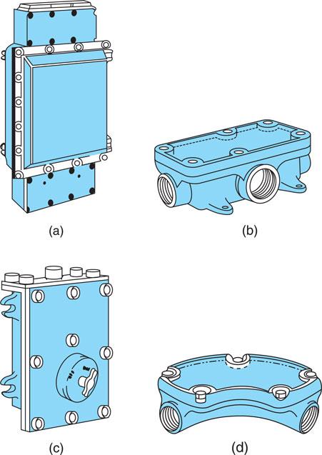
Figure 5.8 Flameproof fittings: (a) flameproof distribution board; (b) flameproof rectangular junction box; (c) double-pole switch; (d) flameproof inspection bend.

Figure 5.9 Flameproof equipment markings.
Ordinary electrical equipment cannot be installed in zone 0, even when it is flameproof protected. However, many chemical and oil-processing plants are entirely dependent upon instrumentation and data transmission for their safe operation. Therefore, very low-power instrumentation and data-transmission circuits can be used in special circumstances, but the equipment must be intrinsically safe, and used in conjunction with a ‘safety barrier’ installed outside the hazardous area. Intrinsically safe equipment must be marked Ex‘ia’ or Ex‘s’, specially certified for use in zone 0.
Intrinsic safety
By definition, an intrinsically safe circuit is one in which no spark or thermal effect is capable of causing ignition of a given explosive atmosphere. The intrinsic safety of the equipment in a hazardous area is assured by incorporating a Zener diode safety barrier into the control circuit such as that shown in Fig. 5.10. In normal operation, the voltage across a Zener diode is too low for it to conduct, but if a fault occurs, the voltage across Z1 and Z2 will rise, switching them on and blowing the protective fuse. Z2 is included in the circuit as a ‘backup’ in case the first Zener diode fails. An intrinsically safe system, suitable for use in zone 0, is one in which all the equipment, apparatus and interconnecting wires and circuits are intrinsically safe.
Definition
An intrinsically safe circuit is one in which no spark or thermal effect is capable of causing ignition of a given explosive atmosphere.
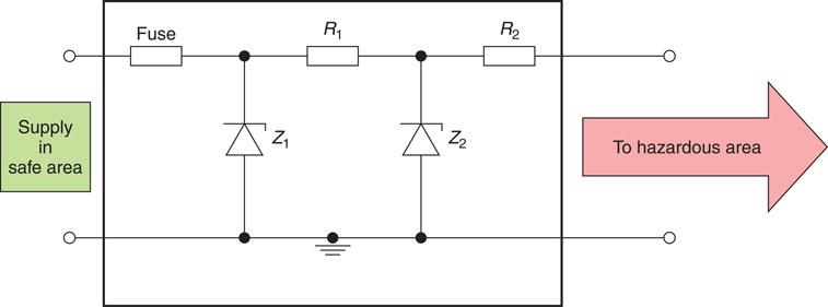
Figure 5.10 Zener safety barrier.
Optical fibre cables
The introduction of fibre-optic cable systems and digital transmissions will undoubtedly affect future cabling arrangements and the work of the electrician. Networks based on the digital technology currently being used so successfully by the telecommunications industry are very likely to become the long-term standard for computer systems. Fibre-optic systems dramatically reduce the number of cables required for control and communications systems, and this will in turn reduce the physical room required for these systems. Fibre-optic cables are also immune to electrical noise when run parallel to mains cables and, therefore, the present rules of segregation and screening may change in the future. There is no spark risk if the cable is accidentally cut and, therefore, such circuits are intrinsically safe. That said there is a danger of blinding a user, should they peer directly at an open-ended termination when the cable is live.
Top tip
Although fibre optics are inherently safer given their use of light as a medium, faults can occur, for instance, if they are not handled with care and their maximum bend radius is exceeded.

Figure 5.11 Fibre-optic cable.
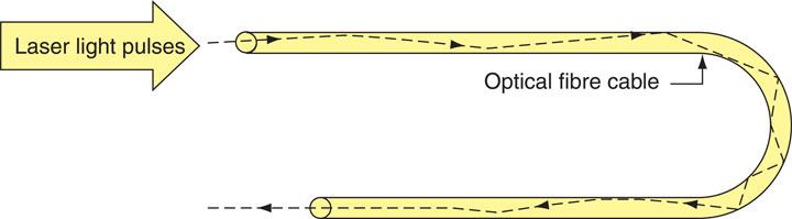
Figure 5.12 Digital pulses of laser light down an optical fibre cable.
The testing of fibre-optic cables requires that special instruments be used to measure the light attenuation (i.e. light loss) down the cable. Finally, when working with fibre-optic cables, electricians should avoid direct eye contact with the low-energy laser light transmitted down the conductors.
Electrostatic discharge
Static electricity is a voltage charge that builds up to many thousands of volts between two surfaces when they rub together. A dangerous situation occurs when the static charge has built up to a potential capable of striking an arc through the air gap separating the two surfaces.
Definition
Static electricity is a voltage change that builds up to many thousands of volts between two surfaces when they run together.
Static charges build up in a thunderstorm. A lightning strike is the discharge of the thunder cloud, which might have built up to a voltage of 100 MV, to the general mass of earth which is at 0 V. Lightning discharge currents are of the order of 20 kA, hence the need for lightning conductors on vulnerable buildings in order to discharge the energy safely.
Static charge builds up between any two insulating surfaces or between an insulating surface and a conducting surface, but it is not apparent between two conducting surfaces.
Safety first
Some equipment that is designated as a static sensitive device could be severely damaged through electrostatic discharge.
A motor car moving through the air builds up a static charge, which sometimes gives the occupants a minor shock as they step out and touch the door handle. Static electricity also builds up in modern offices and similar carpeted areas. The combination of synthetic carpets, man-made footwear materials and dry air conditioned buildings contribute to the creation of static electrical charges building up on people moving about these buildings. Individuals only become aware of the charge if they touch earthed metalwork, such as a stair banister rail, before the static electricity has been dissipated. The effect is a sensation of momentary shock.
Definition
Static charge builds up between any two insulating surfaces or between an insulating surface and a conducting surface, but it is not apparent between two conducting surfaces.
The precautions against this problem include using floor coverings that have been ‘treated’ to increase their conductivity or that contain a proportion of natural fibres that have the same effect. The wearing of leather-soled footwear also reduces the likelihood of a static charge persisting, as does increasing the humidity of the air in the building.
A nylon overall and nylon bed sheets build up static charge which is the cause of the ‘crackle’ when you shake them. Many flammable liquids have the same properties as insulators, and therefore liquids, gases, powders and paints moving through pipes build up a static charge. Petrol pumps, operating theatre oxygen masks and car spray booths are particularly at risk because a spark in these situations may ignite the flammable liquid, powder or gas.
So how do we protect ourselves against the risks associated with static electrical charges? I said earlier that a build-up of static charge is not apparent between two conducting surfaces, and this gives a clue to the solution. Bonding surfaces together with protective equipotential bonding conductors prevents a build-up of static electricity between the surfaces. If we use large-diameter pipes, we reduce the flow rates of liquids and powders and, therefore, we reduce the build-up of static charge. Hospitals use cotton sheets and uniforms, and use protective equipotential bonding extensively in operating theatres. Rubber, which contains a proportion of graphite, is used to manufacture anti-static trolley wheels and surgeons’ boots. Rubber constructed in this manner enables any build-up of static charge to ‘leak’ away. Increasing humidity also reduces static charge because the water droplets carry away the static charge, thus removing the hazard.
IT equipment
Every modern office now contains computers, and many systems are linked together or networked. Most computer systems are sensitive to variations or distortions in the mains supply and many computers incorporate filters that produce high-protective conductor currents of around 2 or 3 mA. This is clearly not a fault current, but is typical of the current that flows in the circuit protective conductor of IT equipment under normal operating conditions. IET Regulation 543.7 deals with the earthing requirements for the installation of equipment having high protective conductor currents. The IET Guidance Note 7 recommends that IT equipment should be connected to double socket outlets as shown in Figure 5.13.
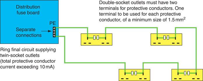
Figure 5.13 Recommended method of connecting IT equipment to socket outlets.
Surge protection
A transient overvoltage or surge is a voltage spike of very short duration. It may be caused by a lightning strike or a switching action on the system. It sends a large voltage spike for a few microseconds down the mains supply, which is sufficient to damage sensitive electronic equipment. Supplies to computer circuits must be ‘clean’ and ‘secure’. Mainframe computers and computer networks are sensitive to mains distortion or interference, which is referred to as ‘noise’. Noise is mostly caused by switching an inductive circuit, which causes a transient spike, or by brush gear making contact with the commutator segments of an electric motor. These distortions in the mains supply can cause computers to ‘crash’ or provoke errors and are shown in Fig. 5.14.
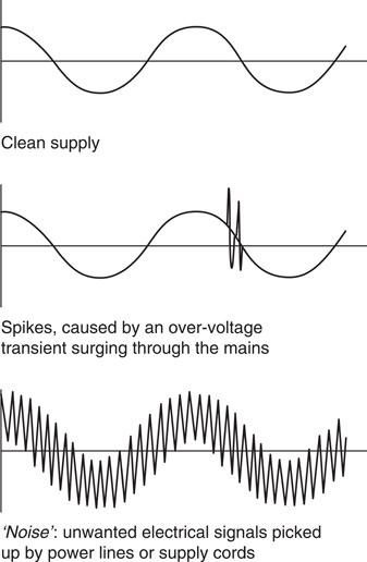
Figure 5.14 Distortions in the a.c. mains supply.
To avoid this, a ‘clean’ supply is required for the computer network. This can be provided by taking the ring or radial circuits for the computer supplies from a point as close as possible to the intake position of the electrical supply to the building. A clean earth can also be taken from this point, which is usually one core of the cable and not the armour of an SWA cable, and distributed around the final wiring circuit. Alternatively, the computer supply can be cleaned by means of a filter such as that shown in Fig. 5.15 or by installing surge protection devices. A surge protection device is a device intended to limit transient overvoltages, and to divert damaging surge currents away from sensitive equipment. Section 534 of the IET Regulations contains the requirements for the installation of surge protective devices (SPDs) to limit transient overvoltages where required by Section 443 of the IET Regulations or where specified by the designer.
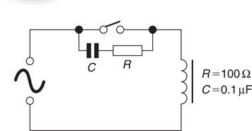
Figure 5.15 A simple noise suppressor.
Damage to electronic devices by ‘overvoltage’
The use of electronic circuits in all types of electrical equipment has increased considerably over recent years. Electronic circuits and components can now be found in leisure goods, domestic appliances, motor starting and control circuits, discharge lighting, emergency lighting, alarm circuits and special-effects lighting systems. All electronic circuits are low-voltage circuits carrying very small currents.
Key fact
All sensitive loads as well as items that can store electrical energy such as capacitors must be disconnected before insulation resistance testing is carried out.
Electrical installation circuits usually carry in excess of 1A and often carry hundreds of amperes. Electronic circuits operate in the milliampere or even microampere range. The test instruments used on electronic circuits must have a high impedance so that they do not damage the circuit when connected to take readings.
The use of an insulation resistance test as described by the IET Regulations (described in Chapter 4 of this book), must be avoided with any electronic equipment. The working voltage of this instrument can cause total devastation to modern electronic equipment. When carrying out an insulation resistance test as part of the prescribed series of tests for an electrical installation, all electronic equipment must first be disconnected or damage will result.
Any resistance measurements made on electronic circuits must be achieved with a battery-operated ohmmeter, with a high impedance to avoid damaging electronic components which is explained further on page 341.
Risks associated with high-frequency or large capacitive circuits
Induction heating processes use high-frequency power to provide focused heating in industrial processes. The induction heater consists of a coil of large cross-section. The work-piece or object to be heated is usually made of ferrous metal and is placed inside the coil. When the supply is switched on, eddy currents are induced into the work-piece and it heats up very quickly so that little heat is lost to conduction and convection.
Definition
Induction heating processes use high-frequency power to provide focused heating in industrial processes.
The frequency and size of the current in the coil determines where the heat is concentrated in the work-piece:
• the higher the current, the greater is the surface penetration;
• the longer the current is applied, the deeper the penetration;
• the higher the frequency, the less is the depth of heat penetration.

Figure 5.16 You may be more familiar with the principle of induction heating than you think – this cooker uses it to cook food.
For shallow penetration, high frequency, high current, short time application is typically used for tool tempering. Other applications are brazing and soldering industrial and domestic gas boiler parts.
When these machines are not working they look very harmless but when they are working they operate very quietly and there is no indication of the intense heat that they are capable of producing. Domestic and commercial microwave ovens operate at high frequency. The combination of risks of high frequency and intense heating means that before any maintenance, repair work or testing is carried out, the machine must first be securely isolated and no one should work on these machines unless they have received additional training to enable them to do so safely.
Industrial wiring systems are very inductive because they contain many inductive machines and circuits, such as electric motors, transformers, welding plants and discharge lighting. The inductive nature of the industrial load causes the current to lag behind the voltage and creates a bad power factor. Power factor is the percentage of current in an alternating current circuit that can be used as energy for the intended purpose. A power factor of say 0.7 indicates that 70% of the current supplied is usefully employed by the industrial equipment.
An inductive circuit, such as that produced by an electric motor, induces an electromagnetic force that opposes the applied voltage and causes the current waveform to lag the voltage waveform. Magnetic energy is stored up in the load during one half cycle and returned to the circuit in the next half cycle. If a capacitive circuit is employed, the current leads the voltage since the capacitor stores energy as the current rises and discharges it as the current falls. So here we have the idea of a solution to the problem of a bad power factor created by inductive industrial loads. Power factor and power factor improvement is discussed below.
Definition
The power factor of the consumer is governed entirely by the electrical plant and equipment that is installed and operated within the consumer’s buildings.
The power factor at which consumers take their electricity from the local electricity supply authority is outside the control of the supply authority. The power factor of the consumer is governed entirely by the electrical plant and equipment that is installed and operated within the consumer’s buildings. Domestic consumers do not have a bad power factor because they use very little inductive equipment. Most of the domestic load is neutral and at unity power factor.
Electricity supply authorities discourage the use of equipment and installations with a low power factor because they absorb part of the capacity of the generating plant and the distribution network to no useful effect. They, therefore, penalize industrial consumers with a bad power factor through a maximum demand tariff, metered at the consumer’s intake position. If the power factor falls below a datum level of between 0.85 and 0.9 then extra charges are incurred. In this way industrial consumers are encouraged to improve their power factor.
Power factor improvement of most industrial loads is achieved by connecting capacitors to either:
• individual items of equipment; or
• banks of capacitors may be connected to the main busbars of the installation at the intake position.
The method used will depend upon the utilization of the installed equipment by the industrial or commercial consumer. If the load is constant then banks of capacitors at the mains intake position would be indicated. If the load is variable then power factor correction equipment could be installed adjacent to the machine or piece of equipment concerned. Power factor correction by capacitors is the most popular method because of the following:
• They require no maintenance.
• Capacitors are flexible and additional units may be installed as an installation or system is extended.
• Capacitors may be installed adjacent to individual pieces of equipment or at the mains intake position. Equipment may be placed on the floor or fixed high up and out of the way.
Capacitors store charge and must be disconnected before the installation or equipment is tested in accordance with Section 6 of the IET Regulations BS 7671.
Small power factor correction capacitors, as used in discharge lighting, often incorporate a high-value resistor connected across the mains terminals. This discharges the capacitor safely when not in use. Banks of larger capacity capacitors may require discharging to make them safe when not in use. To discharge a capacitor safely and responsibly it must be discharged slowly over a period in excess of five ‘time-constants’ through a suitable discharge resistor. Capacitors are discussed in this book in Chapter 6.
Presence of storage batteries
Since an emergency occurring in a building may cause the mains supply to fail, the emergency lighting should be supplied from a source that is independent from the main supply. A battery’s ability to provide its output instantly makes it a very satisfactory source of standby power. In most commercial, industrial and public service buildings housing essential services, the alternative power supply would be from batteries, but generators may also be used. Generators can have a large capacity and duration, but a major disadvantage is the delay of time while the generator runs up to speed and takes over the load. In some premises a delay of more than five seconds is considered unacceptable, and in these cases a battery supply is required to supply the load until the generator can take over. The emergency lighting supply must have an adequate capacity and rating for the specified duration of time (IET Regulation 313.2). BS 5266 and BS EN 1838 states that after a battery is discharged by being called into operation for its specified duration of time, it should be capable of once again operating for the specified duration of time following a recharge period of not longer than 24 hours. The duration of time for which the emergency lighting should operate will be specified by a statutory authority but is normally one to three hours. The British Standard states that escape lighting should operate for a minimum of one hour. Standby lighting operation time will depend upon financial considerations and the importance of continuing the process or activity within the premises after the mains supply has failed.
Definition
Since an emergency occurring in a building may cause the mains supply to fail, the emergency lighting should be supplied from a source that is independent from the main supply.
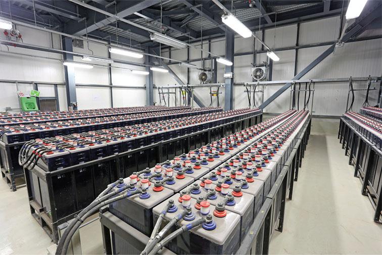
Figure 5.17 Batteries come in all shapes and sizes – these deep charge industrial batteries can store power for long periods.
The contractor installing the emergency lighting should provide a test facility that is simple to operate and secure against unauthorized interference. The emergency lighting installation must be segregated completely from any other wiring, so that a fault on the main electrical installation cannot damage the emergency lighting installation (IET Regulation 528.1). The batteries used for the emergency supply should be suitable for this purpose. Motor vehicle batteries are not suitable for emergency lighting applications, except in the starter system of motor-driven generators. The fuel supply to a motor-driven generator should be checked. The battery room of a central battery system such as that shown in Fig 5.17 must be well ventilated and, in the case of a motor-driven generator, adequately heated to ensure rapid starting in cold weather. The British Standard recommends that the full load should be carried by the emergency supply for at least one hour in every six months. After testing, the emergency system must be carefully restored to its normal operative state. A record should be kept of each item of equipment and the date of each test by a qualified or responsible person. It may be necessary to produce the record as evidence of satisfactory compliance with statutory legislation to a duly authorized person.
Definition
Storage batteries are secondary cells. A secondary cell has the advantage of being rechargeable. If the cell is connected to a suitable electrical supply, electrical energy is stored on the plates of the cell as chemical energy. When the cell is connected to a load, the chemical energy is converted to electrical energy.
Self-contained units are suitable for small installations of up to about 12 units. The batteries contained within these units should be replaced about every five years, or as recommended by the manufacturer.
Storage batteries are secondary cells. A secondary cell has the advantage of being rechargeable. If the cell is connected to a suitable electrical supply, electrical energy is stored on the plates of the cell as chemical energy. When the cell is connected to a load, the chemical energy is converted to electrical energy. A lead-acid cell is a secondary cell. Each cell delivers about 2 V, and when six cells are connected in series a 12 V battery is formed. A lead-acid battery is constructed of lead plates which are deeply ribbed to give maximum surface area for a given weight of plate. The plates are assembled in groups, with insulating separators between them. The separators are made of a porous insulating material, such as wood or ebonite, and the whole assembly is immersed in a dilute sulphuric acid solution in a plastic container. The capacity of a cell to store charge is a measure of the total quantity of electricity that it can cause to be displaced around a circuit after being fully charged. It is stated in ampere-hours, abbreviation Ah, and calculated at the 10-hour rate, which is the steady load current that would completely discharge the battery in 10 hours. Therefore, a 50 Ah battery will provide a steady current of 5A for 10 hours.
Maintenance of lead-acid batteries
The plates of the battery must always be covered by dilute sulphuric acid. If the level falls, it must be topped up with distilled water.
• Battery connections must always be tight and should be covered with a thin coat of petroleum jelly.
• The specific gravity or relative density of the battery gives the best indication of its state of charge. A discharged cell will have a specific gravity of 1.150, which will rise to 1.280 when fully charged. The specific gravity of a cell can be tested with a hydrometer.
• To maintain a battery in good condition it should be regularly trickle-charged. A rapid charge or discharge encourages the plates to buckle, and may cause permanent damage. Most batteries used for standby supplies today are equipped with constant voltage chargers. The principle of these is that after the battery has been discharged by it being called into operation, the terminal voltage will be depressed and this enables a relatively large current (1–5 A) to flow from the charger to recharge the battery. As the battery becomes more fully charged its voltage will rise until it reaches the constant voltage level where the current output from the charger will drop until it is just sufficient to balance the battery’s internal losses. The main advantage of this system is that the battery controls the amount of charge it receives and is therefore automatically maintained in a fully charged condition without human intervention and without the use of any elaborate control circuitry.
• The room used to charge the emergency supply storage batteries must be well ventilated because the charged cell gives off hydrogen and oxygen, which are explosive in the correct proportions.
Assessment criteria 4.1
State the dangers of electricity in relation to the nature of fault diagnosis work
An electrical fault is not a natural occurrence. It is an unplanned event which occurs unexpectedly. The fault may cause a piece of equipment to fail, a production process to stop, or plunge the whole installation into darkness causing normal activities to stop. The electrician trying to find the cause of the fault will be placed in a very stressful environment. That person must have a thorough knowledge and understanding of the electrical systems and equipment, and resolve the problem using a reasoned and logical approach which may involve some live testing.
The tests recommended by the Regulations can be used as a diagnostic tool but the safe working practices described by the Electricity at Work Regulations, discussed elsewhere in this book, must be observed during the fault finding and diagnosis process.
Assessment criteria 4.2
Describe how to identify supply voltages
Construction and Demolition Site Installations (section 704)
Construction and demolition sites are potentially dangerous in many ways. The risk of electric shock is high because of the following factors:
• a construction site or demolition site is, by definition a temporary state. Upon completion there will be either a building with all the necessary safety features, or a brown field site where the building previously stood.
• there is the possibility of damage to cables and equipment as a consequence of the temporary nature of the site and because the site is not always sealed in the early stages from the weather.
• mobile equipment such as electrical tools and hand lamps with trailing leads may be in use.
• there will be many extraneous conductive parts on site which cannot practically be bonded because of the changing nature of the construction process.
Temporary electrical supplies provided on construction sites can save many man hours of labour by providing the energy required for fixed and portable tools and lighting, which speeds up the completion of a project. However, construction sites are dangerous places and the temporary electrical supply that is installed to assist the construction process must comply with all of the relevant wiring regulations for permanent installations (IET Regulation 110.1). All equipment must be of a robust construction in order to fulfil the on-site electrical requirements while being exposed to rough handling, vehicular nudging, the wind, rain and sun. All equipment socket outlets, plugs and couplers must be of the industrial type to BS EN 60439 and BS EN 60309 and specified by IET Regulation 704.511.1 as shown in Fig. 5.18.
IET Regulations 704.313, 704.410.3.10 and 411.8 tell us that reduced low voltage is strongly preferred for portable hand lamps and tools used on construction and demolition sites. The distribution of electrical supplies on a construction site would typically be as follows:
• 400 V three phase for supplies to major items of plant having a rating above 3.75 kW such as cranes and lifts. These supplies must be wired in armoured cables.
• 230 V single phase for supplies to items of equipment that are robustly installed such as floodlighting towers, small hoists and site offices. These supplies must be wired in armoured cable unless run inside the site offices.
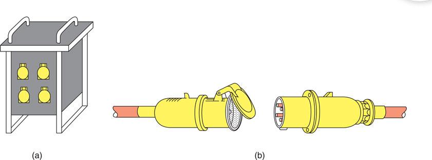
Figure 5.18 110 V distribution unit and cable connector, suitable for construction site electrical supplies: (a) reduced-voltage distribution unit incorporating industrial sockets to BS EN 60309 and (b) industrial plug and connector.
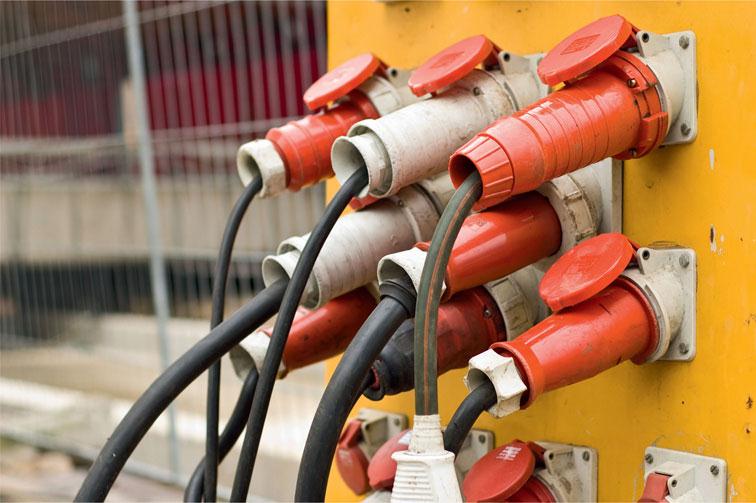
Figure 5.19 Temporary electrical supply.
110 V single phase for supplies to all mobile hand tools and all mobile lighting equipment. The supply is usually provided by a reduced voltage distribution unit that incorporates splashproof sockets fed from a centre-tapped 110 V transformer. This arrangement limits the voltage to earth to 55 V, which is recognized as safe in most locations. A 110 V distribution unit is shown in Fig. 5.18. Edison screw lamps are used for 110 V lighting supplies so that they are not interchangeable with 230 V site office lamps.
There are occasions when even a 110 V supply from a centre-tapped transformer is too high; for example, supplies to inspection lamps for use inside damp or confined places. In these circumstances a safety extra-low voltage (SELV) supply would be required.
Industrial plugs have a keyway that prevents a tool from one voltage being connected to the socket outlet of a different voltage. They are also colour coded for easy identification as follows:
• 400 V – red
• 230 V – blue
• 110 V – yellow
• 50 V – white
• 25 V – violet.
Safety first
Construction sites
Low voltage or battery tools must be used on construction sites.
Assessment criteria 4.3
Select the correct test instruments (in accordance with HSE guidance document GS 38) for fault diagnosis work
Assessment criteria 4.4
Describe how to confirm test instruments are fit for purpose, functioning correctly and are correctly calibrated Selecting test equipment
Selecting test equipment
The HSE has published a guidance note (GS 38) that advises electricians and other electrically competent people on the selection of suitable test probes, voltage-indicating devices and measuring instruments. This is because they consider suitably constructed test equipment to be as vital for personal safety as the training and practical skills of the electrician. In the past, unsatisfactory test probes and voltage indicators have frequently been the cause of accidents, and therefore all test probes must now incorporate the following features:
1 The probes must have finger barriers or be shaped so that the hand or fingers cannot make contact with the live conductors under test.
2 The probe tip must not protrude more than 2 mm, and preferably only 1 mm, be spring-loaded and screened.
3 The lead must be adequately insulated and coloured so that one lead is readily distinguished from the other.
4 The lead must be flexible and sufficiently robust.
5 The lead must be long enough to serve its purpose but not too long.
6 The lead must not have accessible exposed conductors even if it becomes detached from the probe or from the instrument.
GS 38 also tells us that where the test is being made simply to establish the presence or absence of a voltage, the preferred method is to use a proprietary test lamp or voltage indicator that is suitable for the working voltage, rather than a multimeter. Accident history has shown that incorrectly set multimeters or makeshift devices for voltage detection have frequently caused accidents.
Figure 4.2 shows a suitable voltage indicator. Test lamps and voltage indicators are not fail-safe, and therefore GS 38 recommends that they should be regularly proved, preferably before and after use, as described previously in the flowchart for a safe isolation procedure. The IET Regulations (BS 7671) also specify the test voltage or current required to carry out particular tests satisfactorily. All testing must, therefore, be carried out using an ‘approved’ test instrument if the test results are to be valid.
The test instrument must also carry a calibration certificate, otherwise the recorded results may be void. Calibration certificates usually last for a year. Test instruments must, therefore, be tested and recalibrated each year by an approved supplier. This will maintain the accuracy of the instrument to an acceptable level, usually within 2% of the true value. Modern digital test instruments are reasonably robust, but to maintain them in good working order they must be treated with care. An approved test instrument costs as much as a good-quality camera; it should, therefore, receive the same care and consideration.
Continuity tester
To measure accurately the resistance of the conductors in an electrical installation, we must use an instrument that is capable of producing an open circuit voltage of between 4 and 24 V a.c. or d.c., and delivering a short-circuit current of not less than 200 mA (IET Regulation 643.2.1). The functions of continuity testing and insulation resistance testing are usually combined in one test instrument.
Insulation resistance tester
The test instrument must be capable of detecting insulation leakage between live conductors and between live conductors and earth. To do this and comply with IET Regulation 643.3 the test instrument must be capable of producing a test voltage of 250, 500 or 1,000 V and delivering an output current of not less than 1 mA at its normal voltage.
Earth fault loop impedance tester
The test instrument must be capable of delivering fault currents as high as 25 A for up to 40 ms using the supply voltage. During the test, the instrument does an Ohm’s law calculation and displays the test result as a resistance reading.
RCD tester
Where circuits are protected by an RCD we must carry out a test to ensure that the device will operate very quickly under fault conditions and within the time limits set by the IET Regulations. The instrument must, therefore, simulate a fault and measure the time taken for the RCD to operate. The instrument is, therefore, calibrated to give a reading measured in milliseconds to an in-service accuracy of 10%. If you purchase good-quality ‘approved’ test instruments and leads from specialist manufacturers they will meet all the regulations and standards and therefore give valid test results. However, to carry out all the tests required by the IET Regulations will require a number of test instruments and this will represent a major capital investment in the region of £1,000. The specific tests required by the IET Regulations: BS 7671 are described in detail in Chapter 4 of this book under the sub-heading ‘Inspection and testing techniques’.
Electrical installation circuits usually carry in excess of 1 A and often carry hundreds of amperes. Electronic circuits operate in the milliampere or even microampere range. The test instruments used on electronic circuits must have a circuit because they consume some power in order to provide the torque required to move the pointer. In power applications these small disturbances seldom give rise to obvious errors, but in electronic circuits a small disturbance can completely invalidate any readings taken. We must, therefore, choose our electronic test equipment with great care as described in Chapter 4 of this publication.
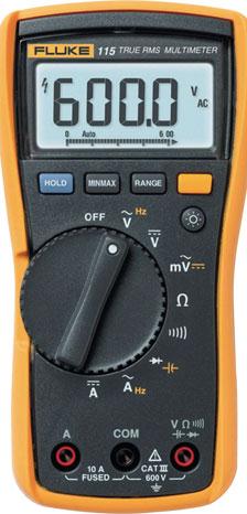
Figure 5.20 Digital multimeter suitable for testing electrical and electronic circuits.
So far in this chapter, I have been considering standard electrical installation circuits wired in conductors and cables using standard wiring systems. However, you may be asked to diagnose and repair a fault on a system that is unfamiliar to you or outside your experience and training. If this happens to you, I would suggest that you immediately tell the person ordering the work or your supervisor that it is beyond your knowledge and experience. I have said earlier that fault diagnosis can only be carried out successfully by someone with a broad range of experience and a thorough knowledge of the installation or equipment that is malfunctioning. The person ordering the work will not think you a fool for saying straightaway that the work is outside your experience. It is better to be respected for your honesty than to attempt something that is beyond you at the present time and which could create bigger problems and waste valuable repair time. Let us now consider some situations where special precautions or additional skills and knowledge may need to be applied.
Assessment criteria 4.5
State the appropriate documentation that is required for fault diagnosis work and explain how and when it should be completed
Assessment criteria 4.8
Identify whether test results are acceptable and state the actions to take where unsatisfactory results are obtained
Assessment criteria 5.3
State the appropriate documentation that is required for fault correction work and explain how and when it should be completed
Various types of information are required when engaging in fault-finding. This can and should include the IET Wiring Regulations BS 7671, which contain essential data such as earth loop impedance and insulation resistance values. This is especially important regarding insulation resistance since BS 7671 stipulates that a reading of 1 MΩ complies with BS 7671 but does warrant further investigation, which could mean further expenditure for the customer. Moreover, BS 7671 can be used to obtain the appropriate level of index protection that equipment requires, size of circuit and protective conductors, as well as rating and classification of protective devices. Maintenance records can be accessed in order to determine why certain components were replaced including any relevant or re-occurring symptoms or sharp degradation of insulation resistance values. Manufacturers’ information such as manuals and user guides can also assist in defining if equipment is faulty or malfunctioning or simply not being operated in the correct mode of operation as designed. This is a very important part of commissioning an installation whereby the hand over process would include, where necessary, a demonstration of how certain equipment operates.
Schedules of previous testing can compare current results against previous readings, such as insulation values, whereby slow deterioration is indicative of a gradual decline due to ageing of the system. This is in comparison with a sharp decline, which is more likely to have been caused by inadvertent component failure or work activity.
Assessment criteria 4.6
Explain why carrying out fault diagnosis work can have implications for customers and clients
Assessment criteria 5.4
Explain how and why relevant people need to be kept informed during completion of fault correction work
Live testing
The Electricity at Work Regulations tell us that it is ‘preferable’ that supplies be made dead before work commences (Regulation 4(3)). However, they do acknowledge that some work, such as fault finding and testing, may require the electrical equipment to remain energized. Therefore, if the fault finding and testing can only be successfully carried out ‘live’, then the person carrying out the fault diagnosis must:
• be trained so that he understands the equipment and the potential hazards of working live and can, therefore, be deemed to be ‘competent’ to carry out the activity;
• only use approved test equipment;
• set up barriers and warning notices so that the work activity does not create a situation dangerous to others.
Note that while live testing may be required in order to find the fault, live repair work must not be carried out. The individual circuit or item of equipment must first be isolated.
Inevitably, both testing and fault finding will affect the supply of an installation irrespective of what environment you are working in. Although in certain circumstances, if it can be justified, work around live supplies may be permitted subject to certain safety measures, undertaking fault finding in an industrial, commercial or domestic environment can disrupt any meaningful activity or production that requires electricity. It is vital therefore that the communication stream is maintained in order to give people fair warning of disruption, when this is necessary. Planning of some maintenance events can alleviate disruption by being implemented during quiet hours either during the night, weekend and even in some cases over bank holidays. Failure to incorporate such measures is effectively a serious breakdown of communication, causing not only tension when information is not cascaded down, but in certain situations can also impinge on the safety of the persons engaged in or affected by the work activities. A further consideration is the detrimental effect it may have on customer relations or even souring the working relationship with another company engaged in similar operations in the same vicinity.
Assessment criteria 5.1
Identify and explain factors that can affect fault correction, repair or replacement
Faulty equipment: to repair or replace?
Having successfully diagnosed the cause of the fault we have to decide if we are to repair or replace the faulty component or piece of equipment. In many cases the answer will be straightforward and obvious, but in some circumstances the solution will need to be discussed with the customer. Some of the issues that may be discussed are as follows:
• What is the cost of replacement? Will the replacement cost be prohibitive? Is it possible to replace only some of the components? Will the labour costs of the repair be more expensive than a replacement? Do you have the skills necessary to carry out the repair? Would the repaired piece of equipment be as reliable as a replacement?
• Is a suitable replacement available within an acceptable time? These days, manufacturers carry small stocks to keep costs down.
• Can the circuit or system be shut down to facilitate a repair or replacement?
• Can alternative or temporary supplies and services be provided while replacements or repairs are carried out?
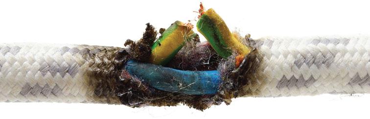
Figure 5.21 Some things have to be replaced for health and safety reasons, like the cable shown above.
Assessment criteria 5.2
Specify the procedures for functional testing and identify tests that can verify fault correction
Assessment criteria 4.7
Specify the procedures for functional testing and identify tests that verify fault correction
Restoring systems to working order
When the fault has been identified and repaired as described in this chapter, the circuit, system or equipment must be inspected, tested and functional checks carried out as required by IET Regulations Chapter 61. The purpose of inspecting and testing the repaired circuit, system or equipment is to confirm the electrical integrity of the system before it is re-energized.
The tests recommended by Part 6 of the IET Regulations are:
1 Test the continuity of the protective conductors including the protective equipotential and supplementary bonding conductors.
2 Test the continuity of all ring final circuit conductors.
3 Test the insulation resistance between live conductors and earth.
4 Test the polarity to verify that single pole control and protective devices are connected in the line conductor only.
5 Test the earth electrode resistance where the installation incorporates an earth electrode as a part of the earthing system.
The supply may now be connected and the following tests carried out:
6 Test the polarity using an approved test lamp or voltage indicator.
7 Test the earth fault loop impedance where the protective measures used require a knowledge of earth fault loop impedance.
These tests where relevant must be carried out in the order given above to comply with IET Regulation 643.1.
If any test indicates a failure, that test and any preceding test must be repeated after the fault has been rectified. This is because the earlier tests may have been influenced by the fault.
The above tests are described in Chapter 4 of this book, in Part 6 of the IET Regulations and in Guidance Note 3 published by the IET.
Following the relevant tests described above we must carry out functional testing to ensure that:
Key fact
GN3 speciti es in Chapter 1 general requirements that when an addition or alteration has been carried out then the minimum tests required are protective conductor continuity and earth fault loop impedance.
• the circuit, system or equipment works correctly;
• it works as it did before the fault occurred;
• t continues to comply with the original specification;
• it is electrically safe;
• it is mechanically safe;
• it meets all the relevant regulations, in particular the IET Regulations (BS 7671).
IET Regulation 643.10 tells us to check the effectiveness of the following assemblies to show that they are properly mounted, adjusted and installed:
• residual current devices (RCDs);
• switchgear;
• control gear;
• controls and interlocks.
Assessment criteria 5.5
Specify the methods for restoring the condition of building fabric
Restoration of the building structure
If the structure, or we sometimes call it the fabric, of the building has been damaged as a result of your electrical repair work, it must be made good before you hand the installation, system or equipment back to the client.
Definition
A major consideration of making good is to use non-combustible material.
Where a wiring system passes through elements of the building construction such as floors, walls, roofs, ceilings, partitions or cavity barriers, the openings remaining after the passage of the wiring system must be sealed according to the degree of fire resistance demonstrated by the original building material (IET Regulation 527.2).
You should always make good the structure of the building using appropriate materials before you leave the job so that the general building structural performance and fire safety are not reduced. If, additionally, there is a little cosmetic plastering and decorating to be done, then who will actually carry out this work is a matter of negotiation between the client and the electrical contractor.
Assessment criteria 5.6
State the methods to ensure the safe disposal of any waste and that the work area is left in a safe and clean condition
Disposal of waste
Having successfully diagnosed the electrical fault and carried out the necessary repairs or having completed any work in the electrical industry, we come to the final practical task, leaving the site in a safe and clean condition and the removal of any waste material. This is an important part of your company’s ‘good customer relationships’ with the client. We know that we have a ‘duty of care’ for the waste that we produce as an electrical company.
We have also said many times in this book that having a good attitude to health and safety, working conscientiously and neatly, keeping passageways clear and regularly tidying up the workplace are signs of a good and competent craftsman. But what do you do with the rubbish that the working environment produces? Well, all the packaging material for electrical fittings and accessories usually goes into either your employer’s skip or the skip on site designated for that purpose.
However, some substances require special consideration and disposal. We will now look at asbestos and large quantities of used fluorescent tubes, which are classified as ‘special waste’ or ‘hazardous waste’.
Asbestos is a mineral found in many rock formations. When separated it becomes a fluffy, fibrous material with many uses. It was used extensively in the construction industry during the 1960s and 1970s for roofing material, ceiling and floor tiles, fire resistant board for doors and partitions, for thermal insulation and commercial and industrial pipe lagging.
In the buildings where it was installed some 40 years ago, when left alone, it does not represent a health hazard, but those buildings are increasingly becoming in need of renovation and modernization. It is in the dismantling and breaking up of these asbestos materials that the health hazard increases. Asbestos is a serious health hazard if the dust is inhaled. The tiny asbestos particles find their way into delicate lung tissue and remain embedded for life, causing constant irritation and, eventually, serious lung disease.
Working with asbestos materials is not a job for anyone in the electrical industry. If asbestos is present in situations or buildings where you are expected to work, it should be removed by a specialist contractor before your work commences. Specialist contractors, who will wear fully protective suits and use breathing apparatus, are the only people who can safely and responsibly carry out the removal of asbestos. They will wrap the asbestos in thick plastic bags and store them temporarily in a covered and locked skip. This material is then disposed of in a special landf ll site with other toxic industrial waste materials and the site monitored by the Local Authority for the foreseeable future.
Safety first
If your electrical activities cause damage to the fabric of the building then:
• the openings remaining must be sealed according to the degree of fire resistance demonstrated by the original building material.
IET Regulation 527.2
All the offcuts of conduit, trunking and tray also go into the skip.
• In fact, most of the general site debris will probably go into the skip and the waste disposal company will take the skip contents to a designated local council landfill area for safe disposal.
• The part coils of cable and any other reusable leftover lengths of conduit, trunking or tray will be taken back to your employer’s stores area. Here it will be stored for future use and the returned quantities deducted from the costs allocated to that job.
• What goes into the skip for normal disposal into a landfill site is usually a matter of common sense.
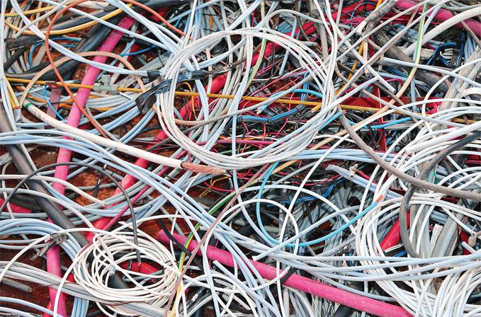
Figure 5.22 Disposing of waste in this manner can be harmful to wildlife.
There is a lot of work for electrical contractors in many parts of the country, updating and improving the lighting in government buildings and schools. This work often involves removing the old fluorescent fittings hanging on chains or fixed to beams and installing a suspended ceiling and an appropriate number of recessed modular LED fittings. So what do we do with the old fittings? Well, the fittings are made of sheet steel, a couple of plastic lamp holders, a little cable, a starter and ballast. All of these materials can go into the ordinary skip. However, the fluorescent tubes contain a little mercury and fluorescent powder with toxic elements, which cannot be disposed of in the normal land-fill sites. Hazardous Waste Regulations were introduced in July 2005 and under these regulations lamps and tubes are classified as hazardous. While each lamp contains only a small amount of mercury, vast numbers of lamps and tubes are disposed of in the United Kingdom every year resulting in a significant environmental threat. The environmentally responsible way to dispose of fluorescent lamps and tubes is to recycle them.
Test your knowledge
When you have completed the questions check out the answers at the back of the book.
Note: more than one multiple-choice answer may be correct.
Learning outcome 1
1 Which of the following is correct regarding safe isolation and investigating an electrical fault?
a. begin investigation, verify circuit is dead, isolate and lock off, re-check voltage device
b. obtain permission, check voltage device, verify circuit is dead, isolate and lock off, re-check voltage device, begin investigation
c. begin work, lock off, verify circuit is dead, re-check voltage device, begin investigation
d. obtain permission, isolate and lock off, check voltage device, verify circuit is dead, re-check voltage device, begin investigation.
2 The very first action involved in carrying out safe isolation is to:
a. test the circuit
b. shut off, lock off then assess all hazards
c. assess all hazards through a risk assessment
d. carry out a full functional test.
3 When applying safe isolation protocols you:
a. can work on live circuits
b. can use the circuit identification as found
c. need to correctly identify the circuit
d. can use the mains to check test equipment.
4 The HSE recommends which of the following in order to embrace safety?
a. approved volt stick
b. equipment listed and endorsed by BS 7671
c. equipment listed and endorsed by GS38
d. approved neon screwdriver.
5 The legislation that prohibits live working except in exceptional circumstances is:
a. Provision and Use of Work Equipment Regulations (1992)
b. Personal Protective Equipment Regulations (1992)
c. BS 7671 Requirements for Electrical Installations
d. Electricity at Work Regulations (1989).
Learning outcome 2
6 Whilst carrying out fault diagnosis, a serious issue has come to light. You actions should be to:
a. leave the circuit as it is and go and inform the client in a clear and courteous manner
b. ensure the circuit is safe then go and inform the client in a clear and courteous manner
c. complete the investigation and then inform the client in a clear and courteous manner
d. carry on with the investigation and then inform the client when you see them next.
7 Keeping the customer abreast of development and any correction work in a clear, courteous and accurate manner:
a. makes good business sense
b. ensures that safety is maintained
c. can boost your earnings
d. justifies any extra expense.
8 Which of the following will physically reduce the possibility of interference from unauthorized personnel?
a. barriers
b. polite notices
c. secure locking devices
d. multiple number of keys.
9 Notices can only be effective if:
a. they are well positioned
b. they inform management only
c. they are clear and accurate
d. they are popular.
10 When fault finding, which of the following apply to customer relations?
a. the electrician needs to be flexible and sensitive regarding when supply can be isolated
b. the electrician needs to be discourteous if they encounter a customer
c. the electrician does not have to worry about the impact of noise
d. the electrician does not have to worry about any damage incurred.
11 If an electrician informs a client of the need to isolate the supply:
a. there is no need for any more control measures
b. there is no further health and safety obligation required
c. it will remind the client of the importance of turning the supply back on
d. the implication and timing when supply is turned off can be discussed.
Learning outcome 3
12 Which of the following has priority?
a. establish the events that led up to the problem
b. check if supply is present
c. check if any protective devices have operated
d. check rating of protective devices.
13 Isolating a power supply includes:
a. switching off secondary supplies only
b. switching off primary supplies only
c. discharging only stored energy
d. isolating and discharging all forms of energy.
14 The symptom of a high resistance joint could include:
a. burning smell
b. protective device operating
c. collection of moisture
d. corrosion.
15 High resistance joints (terminations) are associated with:
a. unsheathed cables
b. loose connection
c. over-tightened connection
d. damaged conductors.
16 Typical symptoms of excessive circuit current include:
a. an undersized conductor
b. protective device operating
c. melting of conductor insulation
d. an oversized conductor.
17 If the solenoid contacts of a relay became open circuit, what would happen when power was applied?
a. the relay would operate as advertised and pull in, but very quickly get hot
b. the relay would fail to operate
c. the relay would chatter
d. the relay would get hot.
18 If the contacts of a relay were to be short circuited, what would happen when power was applied?
a. the relay would operate without being energized
b. the relay would fail to operate
c. the relay would chatter
d. the relay would get hot.
19 Symptoms associated with a high resistance termination and excessive volt drop are:
a. light appearing dim
b. tripping of protective devices
c. motors slow to operate
d. cables becoming hot.
20 Which of the following apply to IT equipment?
a. static sensitive devices
b. clean earths
c. uninterruptable supply
d. sensitivity regarding IR testing.
21 Discovering moisture within an enclosure is symptomatic of issues in relation to:
a. insulation resistance
b. fault protection
c. index protection
d. basic protection.
22 Discovering a copper cable that has been terminated with an aluminium crimp will require the cable to be re-terminated or replaced. This is because of:
a. dissimilar metal corrosion
b. protective device will operate
c. volt drop issues
d. termination contact resistance will be low.
Learning outcome 4
23 One of the dangers of electricity in relation to testing and fault finding is that
a. the supply may need to be dead
b. the supply may need to be live
c. manufacturing may be affected
d. heavy fines are possible.
24 When conducting voltage measurements, which of the following will more likely stop inadvertent tripping of RCDs?
a. equipment with a valid calibration
b. approved equipment listed within GS38
c. expensive equipment
d. extremely sensitive equipment.
25 When diagnosing faults, which of the following can aid diagnosis?
a. questioning customers
b. maintenance records
c. previous test results
d. manufacturer’s warranty.
26 Following replacement of a faulty piece of equipment, completion of this particular task would include:
a. full functional test
b. completion of job sheet
c. replace any protective devices that operated
d. full set of dead tests.
27 Looking at the circuit diagram below, if the voltmeter across the load measures 12V, what should the other voltmeter read?
a. 0 V
b. 12 V
c. 36 V
d. 6 V.
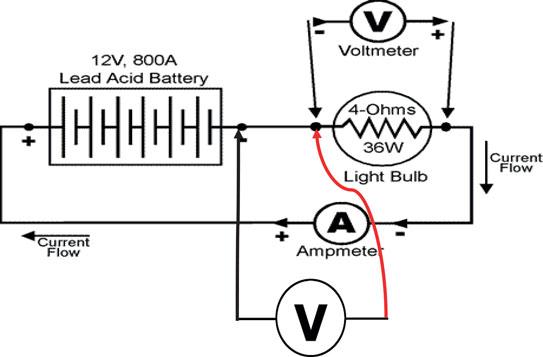
28 Looking at the circuit diagram below, if the voltmeter across the load measures 12 V, what should the other voltmeter read?
a. 0 V
b. 12 V
c. 36 V
d. 6 V.
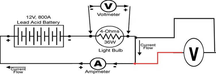
29 With an open circuit as shown in the diagram below, if the voltmeter across the load measures 12 V, what should the other voltmeter read?
a. 0 V
b. 12 V
c. 36 V
d. 6 V.
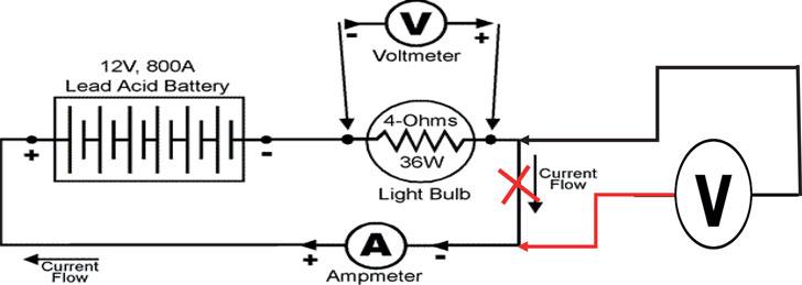
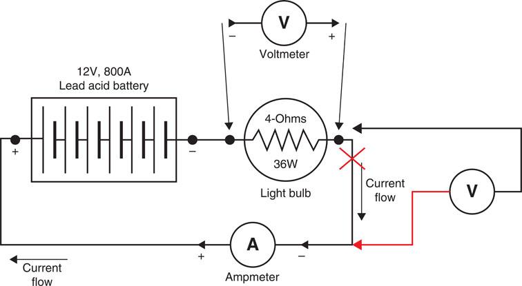
30 A circuit breaker tripping is symptomatic of:
a. an open circuit
b. a short circuit
c. a high resistance
d. a faulty circuit breaker.
31 Lights appearing dim is symptomatic of:
a. excessive length of cable
b. short circuit
c. high resistance
d. volt drop issues.
32 Melting insulation is symptomatic of:
a. excessive length of cable
b. a short circuit
c. high resistance
d. undersized conductor.
33 Excessive volt drop means that the voltage at the supply end:
a. is less than the voltage at the consumer load
b. is more than the voltage at the consumer load
c. is the same as the voltage at the consumer load
d. is double the voltage at the consumer load.
34 A burnt out relay is symptomatic of:
a. excessive circuit volt drop
b. excessive circuit resistance
c. excessive circuit current
d. incorrect rating.
35 An electrical termination should:
a. be accessible
b. be mechanically sound
c. be electrically sound
d. be undersized if possible.
36 If the circuit cable supplying the solenoid element of a heavy duty contactor became open circuit, which of the following would correctly match the symptom?
a. the contactor would energize but instantly drop out
b. the contactor would fail to energize
c. the contactor would energize but start to chatter
d. the contactor would work as normal but would soon overheat.
37 If the normally open switch that supplies the solenoid element of a heavy duty contactor shorted out, which of the following would correctly match the symptom?
a. the contactor would energize but instantly drop out
b. the contactor would fail to operate
c. the contactor would energize without being functionally switched
d. the contactor would de-energize when the normally closed switched is operated but then re-energize.
38 Which of the following tests can ascertain the serviceability of a solenoid?
a. insulation resistance
b. resistance measurement
c. power rating measurement
d. power factor measurement.
39 Increased circuit resistance could be symptomatic of:
a. undersized conductor
b. oversized conductor
c. corrosion
d. stripped or damaged conductor strands.
Learning outcome 5
40 Which of the following would influence the decision if a replacement part is repaired or replaced?
a. cost
b. effect on production
c. availability of replacement parts
d. access.
41 Which of the following is a major consideration of making good?
a. colour
b. cost
c. nonflammable material
d. soundproof.
42 The correct procedure for disposing of fluorescent tubes is:
a. in black plastic bags having smashed them to bits
b. in cardboard boxes to protect against the glass shards
c. through landfill
d. using a hazardous waste management company.
43 Keeping relevant people informed during fault correction work will:
a. speed up fault correction
b. keep everyone happy
c. keep everyone safe
d. bring about agreement on the best possible solution.
Classroom activities
Fault symptoms
Match one of the numbered boxes to each lettered box on the left.
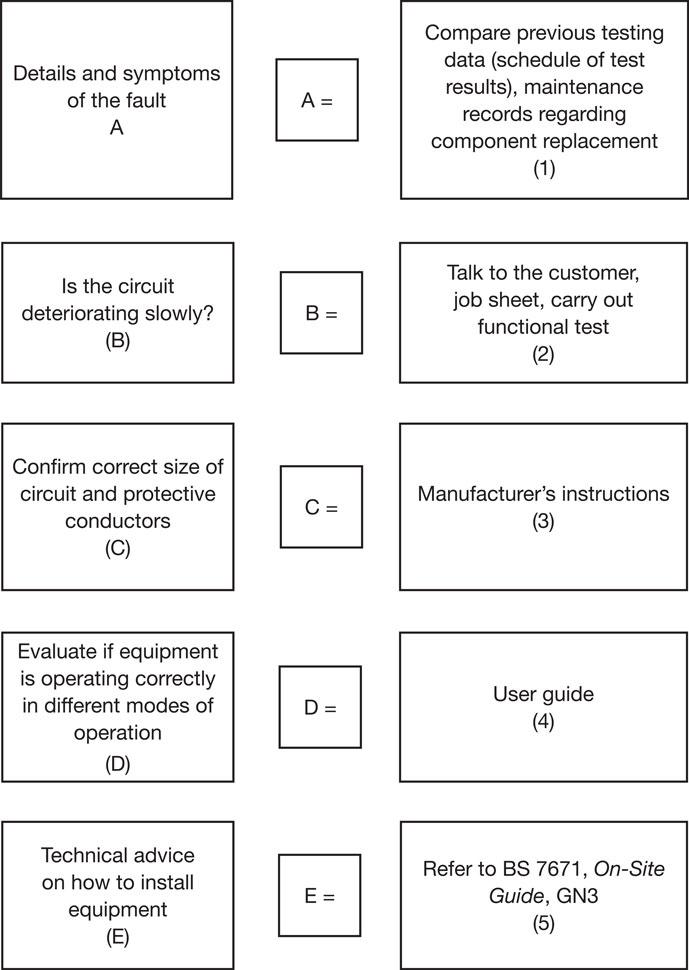
Symptoms and corrective action
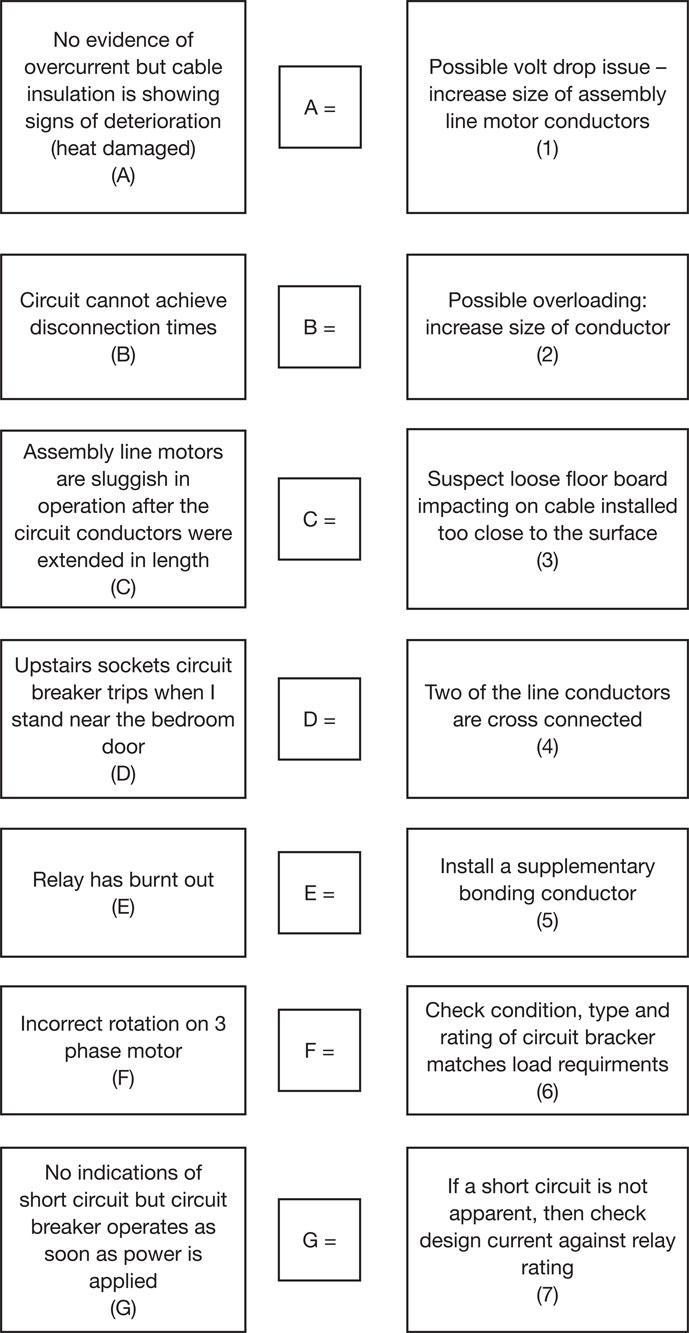
Isolating a power supply includes:QELTK3/007 Understanding the principles, practices and legislation for the diagnosing and correcting of electrical faults in electrotechnical systems and equipment in buildings, structures and the environment
Chapter checklist
Learning outcome |
Assessment criteria |
Page number |
|---|---|---|
1. Understand the principles, regulatory requirements and procedures for completing the safe isolation of electrical circuits and complete electrical installations. |
1.1 Specify and undertake the correct procedure for completing the safe isolation of an electrical circuit with regard to: • assessment of safe working practices • correct identification of circuits to be isolated • the selection of suitable points of isolation • the selection of correct test and proving instruments in accordance with relevant industry guidance and standards • the use of correct testing methods • the selection of locking devices for securing isolation • the use of correct warning notices • the correct sequence for isolating circuits. |
266 |
1.2 State the implications of carrying out safe isolations to: • other personnel • customers/clients • public • building systems (loss of supply). |
267 |
|
1.3 State the implications of not carrying out safe isolations to: • self • other personnel • customers/clients • public • building systems (presence of supply). |
270 |
|
1.4 Identify all health and safety requirements that apply when diagnosing and correcting electrical faults in electrotechnical systems and equipment including those that cover: • working in accordance with risk assessments / permits to work/method statements • safe use of tools and equipment • safe and correct use of measuring instruments • provision and use of PPE • reporting of unsafe situations. |
270 |
|
2. Understand how to complete the reporting and recording of electrical fault diagnosis and correction work. |
2.1 State the procedures for reporting and recording information on electrical fault diagnosis and correction work |
314 |
2.2 State the procedures for informing relevant persons about information on electrical fault diagnosis and correction work and the completion of relevant documentation |
314 |
|
2.3 Explain why it is important to provide relevant persons with information on fault diagnosis and correction work clearly, courteously and accurately |
314 |
|
3. Understand how to complete the preparatory work prior to fault diagnosis and correction work. |
3.1 Specify safe working procedures that should be adopted for completion of fault diagnosis and correction work, including: • effective communication with others in the work area • use of barriers • positioning of notices • safe isolation. |
316 |
3.2 Interpret and apply the logical stages of fault diagnosis and correction work that should be followed: • identification of symptoms • collection and analysis of data • use of sources/types of information such as the IET Wiring Regulations, installation certificates • installation specifications, drawings/diagrams, manufacturer’s information and operating instructions • maintenance records • experience (personal and of others) • checking and testing (e.g. supply, protective devices) • interpreting results/information • fault correction • functional testing • restoration. |
317 |
|
3.3 Identify and describe common symptoms of electrical faults, including: • loss of supply • low voltage • operation of overload or fault current devices • component/equipment malfunction/failure • arcing. |
317 |
|
3.4 State the causes of the following types of fault: • high resistance • transient voltages • insulation failure • excess current • short-circuit • open circuit. |
317 |
|
3.5 Specify the types of faults and their likely locations in: • wiring systems • terminations and connections • equipment/accessories (switches, luminaires, switchgear and control equipment • instrumentation/metering. |
320 |
|
3.6 State the special precautions that should be taken with regard to the following: • lone working • hazardous areas • fibre-optic cabling • electro-static discharge (friction, induction, separation) • electronic devices (damage by over voltage) • IT equipment (e.g. shutdown, damage) • high-frequency or capacitive circuits • presence of batteries (e.g. lead acid cells, connecting cells). |
322 |
|
4. Understand the procedures and techniques for diagnosing electrical faults. |
4.1 State the dangers of electricity in relation to the nature of fault diagnosis work. |
335 |
4.2 Describe how to identify supply voltages. |
336 |
|
4.3 Select the correct test instruments (in accordance with HSE guidance document GS 38) for fault diagnosis work, including: • voltage indicator • low resistance ohmmeter • Insulation resistance testers • EFLI and PFC tester • RCD tester • tong tester/clamp on ammeter • phase sequence tester. |
338 |
|
4.4 Describe how to confirm test instruments are fit for purpose, functioning correctly and are correctly calibrated. |
338 |
|
4.5 State the appropriate documentation that is required for fault diagnosis work and explain how and when it should be completed. |
340 |
|
4.6 Explain why carrying out fault diagnosis work can have implications for customers and clients. |
341 |
|
4.7 Specify the procedures for functional testing and identify tests that verify fault correction • continuity • insulation resistance • polarity • earth fault loop impedance • RCD operation • current and voltage measurement • phase sequence. |
342 |
|
4.8 Identify whether test results are acceptable and state the actions to take where unsatisfactory results are obtained. |
340 |
|
5. Understand the procedures and techniques for correcting electrical faults. |
5.1 Identify and explain factors that can affect fault correction, repair or replacement, including: • cost • availability of replacement parts, resources and staff • down time (planning) • legal and personal responsibility (e.g. contracts, warranties, relevant personnel) • access to systems and equipment • provision of emergency or stand-by supplies • client demand (continuous supply, out of hours working). |
342 |
5.2 Specify the procedures for functional testing and identify tests that can verify fault correction, including: • continuity • insulation resistance • polarity • earth fault loop impedance • RCD operation • values of current and voltage • phase sequencing. |
342 |
|
5.3 State the appropriate documentation that is required for fault correction work and explain how and when it should be completed |
340 |
|
5.4 Explain how and why relevant people need to be kept informed during completion of fault correction work including; • other workers/colleagues • customers/clients • representatives of other services. |
341 |
|
5.5 Specify the methods for restoring the condition of building fabric including: • brickwork • plastering • decorative finishings • supporting structures. |
343 |
|
5.6 State the methods to ensure the safe disposal of any waste and that the work area is left in a safe and clean condition. |
344 |