Pillar terminal
A pillar terminal is a brass pillar with a hole through the side into which the conductor is inserted and secured with a set-screw. If the conductor is small in relation to the hole it should be doubled back. In order that the conductor does not become damaged, the screw connection should be tight but not overtightened. Fig. 3.79 shows a pillar terminal.
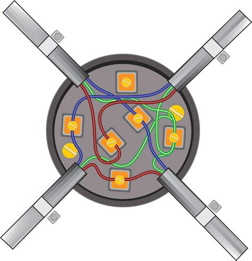
Figure 3.78 Standard junction boxes with screw terminals, junction box must be fixed and cables clamped.
Screwhead, nut and washer terminals
The conductor being terminated is formed into an eye, as shown in Fig. 3.79. The eye should be slightly larger than the screw shank but smaller than the outside diameter of the screwhead, nut or washer. The eye should be placed on the screw shank in such a way that the rotation of the screwhead or nut will tend to close the joint in the eye.
Claw washers
In order to avoid inappropriate separation or spreading of individual wires of multiwire, claw washers are used to obtain a good sound connection. The looped conductor is laid in the pressing as shown in Fig. 3.79, a plain washer is placed on top of the conductor and the metal points folded over the washer. When terminating very fine multiwire conductors, see also 526.9 of the IET Regulations.
Crimp terminals
Crimp terminals are made of tinned sheet copper. The chosen crimp terminal is slipped over the end of the conductor and crimped with the special crimping tool. This type of connection is very effective for connecting protective bonding conductors to approved earth clamps.
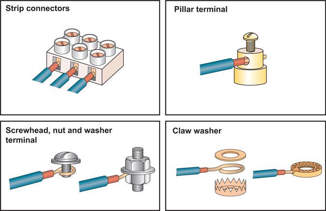
Figure 3.79 Types of terminal.
 Key fact
Whatever method is used to make the connection in conductors, the connection must be both electrically and mechanically sound if we are to avoid high-resistance joints, corrosion and erosion at the point of termination.
Soldered joints or compression joints
Although the soldering of large underground cables is still common today, joints up to about 100A are now usually joined with a compression joint. This uses the same principle as for the crimp termination above; it is just a little larger.
If a large SWA cable must be connected and the joint placed in a position which will be inaccessible for future inspection and testing, then a compression joint encased in a resin compound filled jacket will probably provide a solution.
Regulation 526.3 tells us that every connection must be accessible for inspection and testing except for the following:
1 A joint which is designed to be buried underground such as the one described above.
2 A compound filled or encapsulated joint.
3 A maintenance-free junction box marked with the symbol MF, as shown in Fig. 3.80.
The introduction of this maintenance-free junction box was a small but important change made by Amendment No 1: 2011 of the IET Regulations.
There has always been a debate as to when a junction box is accessible for inspection and testing. Is it accessible when installed under floorboards? Is a screwed down floorboard accessible? Does a fitted carpet make a difference, and who will know where it is?
A maintenance-free junction box does not have to be accessible for inspection and testing, and this new junction box will provide a solution to those difficult and unavoidable situations where there is doubt as to whether a junction box is inaccessible.
Whatever method is used to make the connection in conductors, the connection must be both electrically and mechanically sound if we are to avoid high-resistance joints, corrosion and erosion at the point of termination.

All three images are reproduced here with permission from Wago.
Figure 3.80 A maintenance-free junction box.

Figure 3.81 Both conductors and insulators are found in electrical cable.
Safe terminations and connections
To ensure that all electrical terminations and connections are safe, the installing electrician should give consideration to the following good practice points:
• all connections must be both electrically and mechanically secure;
• all connections must be long lasting and not fail quickly;
• the method of connection must take account of:
– the size of conductor and, therefore, the current carrying capacity of that conductor;
– the material of the conductor; copper is a soft metal but aluminium is softer;
– the number of conductors being connected;
– the temperature to be attained at the point of connection in normal service;
– the provision of adequate locking arrangements in situations subject to vibration.
• every connection must remain accessible for inspection and testing unless designed to be maintence free;
• every connection in a live conductor must be made within:
– a suitable accessory such as a switch, socket ceiling rose or joint box; or
– an equipment enclosure such as a luminaire; or
– a non-combustible enclosure designed for this purpose;
• there must be no mechanical strain put on the conductors or connections. Section 526 of the IET Regulations deals with electrical connections.
132.15 Isolation and switching
Part 4 of the IET Regulations deals with the application of protective measures for safety and Chapter 53 with the regulations for switching devices or switchgear required for protection, isolation and switching of a consumer’s installation.
 Definition
Subtle difference: A switch is an on-load device. An isolator is an off-load device.
The consumer’s main switchgear must be readily accessible to the consumer and be able to:
• isolate the complete installation from the supply;
• protect against overcurrent;
• cut off the current in the event of a serious fault occurring.
The regulations identify four separate types of switching: switching for isolation, switching for mechanical maintenance, emergency switching and functional switching.
Isolation is defined as cutting off the electrical supply to a circuit or item of equipment in order to ensure the safety of those working on the equipment by making dead those parts that are live in normal service.
Definition
Isolation is defined as cutting off the electrical supply to a circuit or item of equipment in order to ensure the safety of those working on the equipment by making dead those parts which are live in normal service.
The purpose of isolation switching is to enable electrical work to be carried out safely on an isolated circuit or piece of equipment. Isolation is intended for use by electrically skilled or supervised persons.
An isolator is a mechanical device which is operated manually and used to open or close a circuit off load. An isolator switch must be provided close to the supply point so that all equipment can be made safe for maintenance. Isolators for motor circuits must isolate the motor and the control equipment, and isolators for discharge lighting luminaires must be an integral part of the luminaire so that it is isolated when the cover is removed or be provided with effective local isolation (IET Regulation 537.2). Devices that are suitable for isolation are isolation switches, fuse links, circuit-breakers, plugs and socket outlets. They must isolate all live supply conductors and provision must be made to secure the isolation (IET Regulation 537.2.5).

Figure 3.82 There are several different types of tool that can be used to ‘lock-off’ circuits.
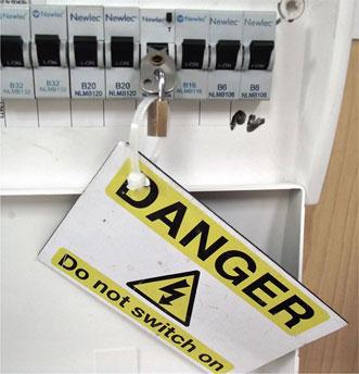
Figure 3.83 This circuit is now isolated and locked off.
Isolation at the consumer’s service position can be achieved by a double pole switch that opens or closes all conductors simultaneously. On three-phase supplies the switch need only break the live conductors with a solid link in the neutral, provided that the neutral link cannot be removed before opening the switch.
The switching for mechanical maintenance requirements is similar to that for isolation except that the control switch must be capable of switching the full load current of the circuit or piece of equipment.
Definition
The switching for mechanical maintenance requirement is similar to that for isolation except that the control switch must be capable of switching the full load current of the circuit or piece of equipment.
The purpose of switching for mechanical maintenance is to enable non-electrical work to be carried out safely on the switched circuit or equipment.
Mechanical maintenance switching is intended for use by skilled but nonelectrical persons. Switches for mechanical maintenance must be manually operated, not have exposed live parts when the appliance is opened, must be connected in the main electrical circuit and have a reliable on/off indication or visible contact gap (IET Regulation 537.3.3). Devices that are suitable for switching off for mechanical maintenance are switches, circuit-breakers, plugs and socket outlets.
Emergency switching involves the rapid disconnection of the electrical supply by a single action to remove or prevent danger. The purpose of emergency switching is to cut off the electrical energy rapidly to remove an unexpected hazard.
Emergency switching is for use by anyone. The device used for emergency switching must be immediately accessible and identifiable, and be capable of cutting off the full load current (see Fig. 3.84).
Definition
Emergency switching involves the rapid disconnection of the electrical supply by a single action to remove or prevent danger.
Electrical machines must be provided with a means of emergency switching, and a person operating an electrically driven machine must have access to an emergency switch so that the machine can be stopped in an emergency.
A remote stop/start or emergency stop arrangement can be added to a direct on line starter to meet the requirements for an electrically driven machine as required by IET Regulation 537.3.3. Devices that are suitable for emergency switching are switches, circuit-breakers and contactors. Where contactors are operated by remote control they should open when the coil is de-energized, that is, fail safe. Pushbuttons used for emergency switching must be coloured red and latch in the stop or off position. They should be installed where danger may arise and be clearly identified as emergency switches. Plugs and socket outlets cannot be considered appropriate for emergency disconnection of supplies.
Functional switching involves the switching on or off, or varying the supply, of electrically operated equipment in normal service. The purpose of functional switching is to provide control of electrical circuits and equipment in normal service. Functional switching is for the user of the electrical installation or equipment. The Building Regulations require that switches and sockets be installed so that all persons, including those whose reach is limited, can reach them. The guidance is shown in Fig. 3.85 and applies to all new dwellings but not to rewires.
Definition
Functional switching involves the switching on or off, or varying the supply, of electrically operated equipment in normal service.
However, these recommendations will undoubtedly ‘influence’ the rewiring of existing dwellings. The device must be capable of interrupting the total steady current of the circuit or appliance. When the device controls a discharge lighting circuit it must have a current rating capable of switching an inductive load. The regulations acknowledge the growth in the number of electronic dimmer switches being used for the control and functional switching of lighting circuits. The functional switch must be capable of performing the most demanding duty it may be called upon to perform (IET Regulations 537.1 and 2).
Definition
The nominated heights of switches and sockets are determined through Part M (Access to buildings) of the Building Regulations not Part P. Part P is electrical safety.
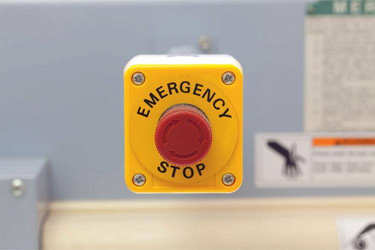
Figure 3.84 Emergency stop control.
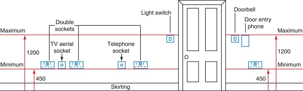
Figure 3.85 Fixing positions of switches and socket outlets.
Protection against fire
Chapter 42 in the wiring regulations contains information regarding protection against fire. The aim of this chapter therefore is to provide directives in order to prevent both fires and burns emanating from the installation of electrical equipment. It does so by examining actual ignition sources, how fire is spread and how burns are produced through processes such as arcing. Overall the heat generated through the equipment must not cause danger or harmful effects, including positioning fixed equipment that emanate heat within a sufficient distance away from any surface (421.1.4). The 18th Edition of the Regulations now recommends the use of metal consumer units in household premises. Also, arc fault detection devises (AFDD) are ‘recommended’ as an additional means of protection against fire. (IET Regulations 421.1.201 and 421.1.7). Other considerations inherent on a designer of an installation concern the use of high-risk equipment such as welding equipment in that not only should consideration be given to equipment guarding but also the material used in the surrounding area should be scrutinized regarding if it is made from materials that might promote the fire. Equally, use of flammable liquid, which is defined by any material that can easily combust, must be positioned so that the burning liquid is contained within the area of use and is not allowed to escape and enlarge the fire.
Key fact
Amendment 3 of BS7671 states that consumer units and similar switchgear assemblies in domestic premises have to be of non-combustible materials such as metal.
When the possibility exists then the equipment should be: screened, mounted or supported within appropriate enclosures or from materials constructed with low thermal conductance (421.1.2). Where arcing is possible the equipment needs to be totally enclosed or protected by arc-resistant material or be positioned away from any material that the emission could have a detrimental effect on (421.1.3).
There are several interlinking elements within the wiring regulations concerning protection against fire. Regulation 532.2 states that where it is necessary to limit the effect of a fault condition from the perspective of a fire then an RCD must be fitted not only to comply with fault protection but should be installed at the circuit origin and be able to switch all live conductors but its rating shall not exceed 300 mA. This is an important consideration regarding fire alarm circuits, since there is potentially a conflict regarding meeting regulation 411.5.2 which specifies that RCD protection is required in TT earthing systems if high earth loop impedance values are recorded. On the other hand, installing an RCD within a fire alarm circuit is not recommended because of the possibility of nuisance tripping. Such a situation is resolved by installing an RCD dedicated to the alarm supply circuit but with a trip rating of 100 mA.
132.4 Electrical supplies for safety systems
Where a supply for safety services or standby electrical systems is required the designer must determine the characteristics of the supply and the services to be supplied by the safety source. Approved document B, fire safety, states that:
• there must be routes for people to escape to a place of safety;
• these routes must be protected from the effects of fire;
• the routes must be adequately illuminated;
• the exits must be suitably signed;
• there is sufficient means of giving early warning of fire to persons in the building.
All of the above must be applied to the extent that is dependent upon the use of the building, its size and its height.
Appendix C of the Electrician’s Guide to the Building Regulations gives guidance on the provision required as follows:
• automatic fire detection and alarms complying with BS 5839 should be installed in institutional and other residential occupancies;
• it is essential that the fire detection systems are properly designed, installed and maintained;
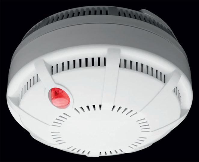
Figure 3.86 Electrical equipment for fire safety.
• where services pass through walls, called fire separating elements, they must be sealed to prevent the passage of smoke and fire.
In dwellings not protected by automatic fire detection and alarm systems, including domestic homes, they are required to be fitted with a suitable number of smoke alarms. The building regulations require all new and refurbished dwellings to be fitted with mains operated smoke alarms. The requirements for a single family dwelling of not more than two storeys are:
• Smoke alarms should normally be positioned in the circulation spaces between sleeping spaces and where fires are most likely to start such as kitchens and living rooms.
• In a house or bungalow there should be at least one smoke alarm on every storey.
• Where more than one smoke alarm is installed they should be linked so that the detection of smoke by one unit operates the alarm in all units.
• Alarms should normally be ceiling-mounted and at least 300 mm from walls and light fittings.
• Where the kitchen area is not separated by a door there should be a heat detector in the kitchen.
• The power supply for a smoke alarm should be derived from the dwelling’s mains electricity supply.
• The cable for the power supply to each self contained unit and the interconnecting cable need have no fire retardant properties and need no segregation from other circuits (BS 52661-1: 2011).
• Smoke alarms that include a standby power supply can operate during a mains failure and therefore may be connected to a regularly used local lighting circuit. This has the advantage that the circuit is unlikely to be disconnected for prolonged periods.
132.5 Environmental conditions
The electrical design must take into account the environmental conditions to which the installation will be subjected. Electrical equipment in surroundings susceptible to risk of fire or explosion shall be constructed or protected so as to prevent danger.
Appendix 5 of the IET Regulations gives us a concise list of external influences. Each condition is designated with a code; A is environment, B is utilization and C is construction of buildings. For example, a code AA4 signifies:
A = environment
AA = environment ambient temperature
AA4 = environment ambient temperature in the range −5°C to + 40°C
Section 522 of the IET Regulations details the installation requirements for:
• ambient temperature;
• external heat sources;
• the presence of water or/and humidity;
• the presence of corrosive or polluting substances;
• mechanical damage and stresses;
• vibration;
• presence of flora, fauna and mould growth;
• solar radiation.
Some installations require special consideration because of the inherent dangers listed above. Installations requiring special consideration are flameproof installations, construction sites, agricultural and horticultural buildings. All of these installations are described in detail in Part 7 of the IET Regulations and some are described in Chapter 3 of this book. Appendix C of the On-Site Guide gives guidance on the selection and types of cable for particular influences.

Figure 3.87 All electrical equipment must be suitable for the installed conditions.
This point in the design process might also be a good time to consider:
• the environmental impact of the design;
• the importance of sustainable design as described at the beginning of this chapter;
• the possible use of environmental technology systems and renewable energy systems as described in Chapter 1 of this book.
Electrical shock
Electric shock occurs when a person becomes part of the electrical circuit, as shown in Fig. 3.104. The lethal level is approximately 50 mA, above which muscles contract, the heart flutters and breathing stops. A shock above the 50 mA level is therefore fatal unless the person is quickly separated from the supply. Below 50 mA only an unpleasant tingling sensation may be experienced or you may be thrown across a room or fall from a roof or ladder, but the resulting fall may lead to serious injury.
Definition
Electric shock occurs when a person becomes part of the electrical circuit.
To prevent people from receiving an electric shock accidentally, all circuits must contain protective devices to operate or isolate a circuit. But you must bear in mind that the primary job of the protective device is to protect the cable since left unchecked the cable insulation surrounding a conductor subjected to a very high fault current will melt and inevitably cause an electrical fire. Protecting the user or person, however, is through additional protection and specifically the use of RCDs. It is no coincidence that RCDs designed to protect power outlets are rated at 30 mA, in other words they will operate before the circuit current reaches the lethal level.
The On-Site Guide lists at section 3.6 when RCDs must be in place and includes:
• when earth loop impedance values are high such as TT earthing systems;
• socket outlets not exceeding 32A.
• low voltage circuits involving a bath or shower;
• mobile equipment not exceeding 32A for use outdoors.
• cables without earthed metallic sheathing/armour installed in walls to a depth less than 50 mm;
• cables not installed in steel conduit or similar.
• lighting circuits in domestic (household) premises.
Consumer units which comply with the 18th Edition requirements, utilise split boards that incorporate one main switch and two RCDs. This ensures that a single fault will only affect one half of the board and thus limit any inconvenience. This also complies with certain requirements that all power sockets and any instances of cables not being enclosed in metal enclosures or installed in walls to a depth of >50 mm are afforded ‘additional protection’.
Construction workers and particularly electricians do receive electric shocks, usually as a result of carelessness or unforeseen circumstances. Temporary electrical supplies on construction sites can save many person-hours of labour by providing energy for fixed and portable tools and lighting. However, as stated previously in this chapter, construction sites are dangerous places and by definition temporary supplies are not as robust as permanent installations.
Certain safeguards must therefore be in place, such as ensuring that the input to temporary electrical supplies are protected by an RCD (704.410.3.10). Other measures include the use of a safety isolation transformer contained within SELV or PELV circuits, both of which limit the operating voltage to <50 V (typically 12 V). The assumption made is that being subjected to 50 V or touch voltage as it is known will not ordinarily be lethal. This is why when calculations are made regarding supplementary bonding or fusing current, the value used is touch voltage, so that it ensures that shock protection systems operate before dangerous voltages are allowed to build up. Such arrangements are known as a reduced voltage system and is mainly why the wiring regulations recommended that all portable hand equipment are supplied through a 110 V transformer. When working on a construction site, or in damp or wet conditions, a SELV system is strongly preferred.
Special locations
Special locations are listed in Part 7, Section 700 of the wiring regulations. They range from locations containing a bath or shower and temporary construction site installations to floor and ceiling heating systems. Each location is divided into zones, describes the level of index protection regarding external influences required, what kind of current-using equipment can be used and where they can be positioned. Additionally, use of supplementary bonding and additional protection through RCDs and protective measures such as SELV and PELV are also detailed. Some of these systems will now be discussed in detail.
Construction and Demolition site installations
Construction and demolition sites are potentially dangerous in many ways. The risk of electric shock is high because of the following factors:
• a construction site or demolition site is, by definition, a temporary state. Upon completion there will be either a building with all the necessary safety features, or a brown field site where the building previously stood.
• there is the possibility of damage to cables and equipment as a consequence of the temporary nature of the site and because the site is not always sealed in the early stages from the weather.
• mobile equipment such as electrical tools and hand lamps with trailing leads may be in use.
• there will be many extraneous conductive parts on site which cannot practically be bonded because of the changing nature of the construction process.
Temporary electrical supplies provided on construction sites can save many man hours of labour by providing the energy required for fixed and portable tools and lighting, which speeds up the completion of a project. However, construction sites are dangerous places and the temporary electrical supply that is installed to assist the construction process must comply with all of the relevant wiring regulations for permanent installations (IET Regulation 110.1). All equipment must be of a robust construction in order to fulfil the on-site electrical requirements while being exposed to rough handling, vehicular nudging, the wind, rain and sun. All equipment socket outlets, plugs and couplers must be of the industrial type to BS EN 60439 and BS EN 60309 and specified by IET Regulation 704.511.1 as shown in Fig. 3.88.
Where an electrician is not permanently on site, CBs are preferred so that overcurrent protection devices can be safely reset by an unskilled person. The British Standards Code of Practice 1017, The Distribution of Electricity on Construction and Building Sites, advises that protection against earth faults may be obtained by first providing a low impedance path, so that overcurrent devices can operate quickly as described in Chapter 4, and secondly by fitting an RCD in addition to the overcurrent protection device (IET Regulation 704.410.3.10). The 18th Edition of the IET Regulations considers construction sites very special locations, devoting the whole of Section 704 to their requirements. A construction site installation should be tested and inspected in accordance with Part 6 of the IET Regulations every three months throughout the construction period. The source of supply for the temporary installation may be from a petrol or diesel generating set or from the local supply company. When the local electricity company provides the supply, the incoming cable must be terminated in a waterproof and locked enclosure to prevent unauthorized access and provide metering arrangements. IET Regulations in Section 704 and 411.8 tell us that reduced low voltage is strongly preferred for portable hand lamps and tools used on construction and demolition sites. The distribution of electrical supplies on a construction site would typically be as follows:
• 400 V three phase for supplies to major items of plant having a rating above 3.75 kW such as cranes and lifts. These supplies must be wired in armoured cables.
• 230 V single phase for supplies to items of equipment that are robustly installed such as flood lighting towers, small hoists and site offices. These supplies must be wired in armoured cable unless run inside the site offices.
• 110 V single phase for supplies to all mobile hand tools and all mobile lighting equipment. The supply is usually provided by a reduced voltage distribution unit, which incorporates splash proof sockets fed from a centre-tapped 110 V transformer. This arrangement limits the voltage to earth to 55 V, which is recognized as safe in most locations. A 110 V distribution unit is shown in Fig. 3.88. Edison screw lamps are used for 110 V lighting supplies so that they are not interchangeable with 230 V site office lamps.
There are occasions when even a 110 V supply from a centre-tapped transformer is too high; for example, supplies to inspection lamps for use inside damp or confined places. In these circumstances a safety extra-low voltage (SELV) supply would be required.
Industrial plugs have a keyway that prevents a tool from one voltage being connected to the socket outlet of a different voltage. They are also colour coded for easy identification as follows:
 Safety first
Construction sites
• Low voltage or
• Battery tools must be used.
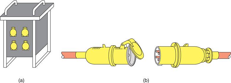
Figure 3.88 110 V distribution unit and cable connector, suitable for construction site electrical supplies (a) reduced-voltage distribution unit incorporating industrial sockets to BS EN 60309 and (b) industrial plug and connector.

Figure 3.89 Temporary electrical supply.
• 400 V – red
• 230 V – blue
• 110 V – yellow
• 50 V – white
• 25 V – violet.
Agricultural and horticultural premises
Especially adverse installation conditions are to be encountered on agricultural and horticultural premises because of the presence of livestock, vermin, dampness, corrosive substances and mechanical damage. The 18th Edition of the IET Wiring Regulations considers these installations very special locations and has devoted the whole of Section 705 to their requirements. In situations accessible to livestock the electrical equipment should be of a type that is appropriate for the external influences likely to occur, and should have at least protection IP44; that is, protection against solid objects and water splashing from any direction (IET Regulation 705.512.2).
In buildings intended for livestock, all fixed wiring systems must be inaccessible to the livestock and cables liable to be attacked by vermin must be suitably protected (IET Regulation 705.513.2). PVC cables enclosed in heavy-duty PVC conduit are suitable for installations in most agricultural buildings. All exposed and extraneous metalwork must be provided with supplementary equipotential bonding in areas where livestock is kept (IET Regulation 705.415.2.1). In many situations, waterproof socket outlets to BS 196 must be installed. All socket outlet circuits must be protected by an RCD complying with the appropriate British Standard and the operating current must not exceed 30 mA. Cables buried on agricultural or horticultural land should be buried at a depth of not less than 600 mm, or 1,000 mm where the ground may be cultivated, and the cable must have an armour sheath and be further protected by cable tiles. Overhead cables must be insulated and installed so that they are clear of farm machinery or placed at a minimum height of 6 m to comply with IET Regulation 705.522. Horses and cattle are susceptible to an electric shock at voltages lower than 25 V r.m.s.
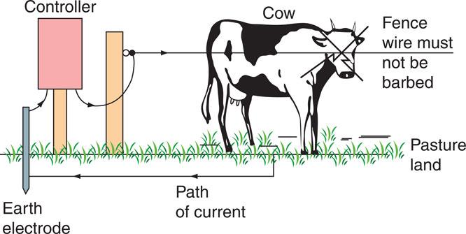
Figure 3.90 Farm animal control by electric fence.
The reasons for this are varied but include that:
• animals have a very low body resistance;
• a big potential difference exists between quadruped animals, in other words between the fore and hind legs;
• horses wear metal shoes;
• the ground can be wet;
• the electric path between fore and hind legs travels straight through the animals heart.
The sensitivity of farm animals to electric shock means that they can be contained by an electric fence. An animal touching the fence receives a short pulse of electricity, which passes through the animal to the general mass of earth and back to an earth electrode sunk near the controller, as shown in Fig. 3.90. The pulses are generated by a capacitor–resistor circuit inside the controller, which may be mains or battery operated (capacitor–resistor circuits are discussed in Chapter 6). There must be no risk to any human coming into contact with the controller, which should be manufactured to BS 2632. The output voltage of the controller must not exceed 10 kV and the energy must not be greater than 5 J. The duration of the pulse must not be greater than 1.5 ms and the pulse must never have a frequency greater than one pulse per second.

Figure 3.91 They say that the grass is greener on the other side of the fence, but one false move and this sheep will get an electric shock.
This shock level is very similar to that which can be experienced by touching a spark plug lead on a motor car. The energy levels are very low at 5 J. There are 3.6 million joules of energy in 1 kWh. Earth electrodes connected to the earth terminal of an electric fence controller must be separate from the earthing system of any other circuit and should be situated outside the resistance area of any electrode used for protective earthing. The electric fence controller and the fence wire must be installed so that they do not come into contact with any power, telephone or radio systems, including poles. Agricultural and horticultural installations should be tested and inspected in accordance with Part 6 of the Wiring Regulations every three years.
Caravans and caravan sites
The electrical installations on caravan sites, and within caravans, must comply in all respects with the wiring regulations for buildings. All the dangers that exist in buildings are present in and around caravans, including the added dangers associated with repeated connection and disconnection of the supply and the flexing of the caravan installation in a moving vehicle. The 18th Edition of the IET Regulations has devoted Section 721 to the electrical installation in caravans and motor caravans and Section 708 to caravan parks. Touring caravans must be supplied from a 16 A industrial type socket outlet adjacent to the caravan park pitch, having a degree of protection of at least IP44 similar to that shown in Fig. 3.92. Each socket outlet must be provided with individual overcurrent protection and an individual residual current circuit-breaker with a rated tripping current of 30 mA (IET Regulations 708.55.1 to 14). The distance between the caravan connector and the site socket outlet must not be more than 25 m (IET Regulation 708.530.3 Regulations Fig 708). These requirements are shown in Fig. 3.92. The supply cables must be installed outside the pitch area and be buried at a depth of at least 0.6 m (IET Regulation 708.521.7.2). The caravan or motor caravan must be provided with a mains isolating switch and an RCD to break all live conductors (IET Regulation 721.411). An adjacent notice detailing how to connect and disconnect the supply safely must also be provided, as shown in IET Regulation 721.514. Electrical equipment must not be installed in fuel storage compartments (IET Regulation 721.528.2.1). Caravans flex when being towed, and therefore the installation must be wired in flexible or stranded conductors of at least 1.5 mm cross-section. The conductors must be supported on horizontal runs at least every 25 cm and the metalwork of the caravan and chassis must be bonded with 4.0 mm2 cable.
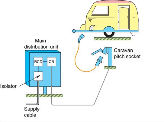
Figure 3.92 Electrical supplies to caravans.
The wiring of the extra low-voltage battery supply must be run in such a way that it does not come into contact with the 230 V wiring system (IET Regulation 721.528.1).
Safety first
Electric shock
Animals and humans must be protected against electric shock.
The caravan should be connected to the pitch socket outlet by means of a flexible cable, not longer than 25 m and having a minimum cross-sectional area of 2.5 mm2 or as detailed in Section 708 Notes and Table 721 of the IET Regulations. Because of the mobile nature of caravans it is recommended that the electrical installation be tested and inspected at intervals considered appropriate, preferably not less than once every three years and annually if the caravan is used frequently (IET Regulation 721 Periodic Inspection Notes).
Key fact
Caravans
• Every caravan pitch must have at least one 16 A industrial socket.
• Each socket must have RCD and overcurrent protection.
IET Regulation 708.533.
Bathroom installations
Rooms containing a fixed bath tub or shower basin are considered an area of increased shock risk and, therefore, additional regulations are specified in Section 701 of the IET Regulations. This is to reduce the risk of electric shock to people in circumstances where body resistance is lowered because of contact with water. The regulations can be summarized as follows:
• Socket outlets must not be installed and no provision is made for connection of portable appliances unless the socket outlet can be fixed 3 m horizontally beyond the zone 1 boundary within the bath or shower room (IET Regulation 701.512.3).
• Only shaver sockets that comply with BS EN 60742, that is those which contain an isolating transformer, may be installed in zone 2 or outside the zones in the bath or shower room (IET Regulation 701.512.3).
• All circuits in a bath or shower room, that is both power and lighting, circuits which are serving the location, or passing through zones 1 and 2 not serving the location, must be additionally protected by an RCD having a rated maximum operating current of 30 mA (IET Regulation 701.411.3.3).
• There are restrictions as to where appliances, switchgear and wiring accessories may be installed. See Zones for bath and shower rooms below.
• Local supplementary equipotential bonding (IET Regulation 701.415.2) must be provided to all gas, water and central heating pipes in addition to metallic baths, unless the following two requirements are both met:
– all bathroom circuits, both lighting and power, are protected by a 30 mA RCD in addition to a circuit breaker or fuse; and
– the bath or shower is located in a building with main protective equipotential bonding in place as described in Fig. 3.106 of this book and (IET Regulation 411.3.1.2 and 701.415.2).
Note: Local supplementary equipotential bonding as shown in Fig 3.93 may be an additional requirement of the Local Authority regulations in, for example, licensed premises, student accommodation and rented property.
Zones for bath and shower rooms
Locations that contain a bath or shower are divided into zones or separate areas as shown in Fig. 3.94.
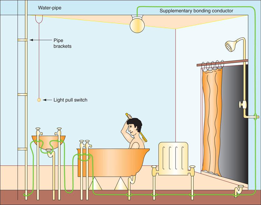
Figure 3.93 Supplementary protective bonding in bathrooms to metal pipework.
Key fact
Bathrooms
All bathroom circuits, both power and lighting, must have additional RCD protection.
Zone 0 – the bath tub or shower basin itself, which can contain water and is, therefore, the most dangerous zone
Zone 1 – the next most dangerous zone in which people stand in water
Zone 2 – the next most dangerous zone in which people might be in contact with water
Outside
Zones – people are least likely to be in contact with water but are still in a potentially dangerous environment and the general IET Regulations apply.
• Spaces under the bath that are accessible ‘only with the use of a tool’ are outside zones;
• Spaces under the bath that are accessible ‘without the use of a tool’ are zone 1.
Electrical equipment and accessories are restricted within the zones.
Zone 0 – being the most potentially dangerous zone, for all practical purposes no electrical equipment can be installed in this zone. However, the IET Regulations permit that whereas SELV fixed equipment with a rated voltage not exceeding 12 V a.c. cannot be located elsewhere, it may be installed in this zone (IET Regulation 701.55). The electrical equipment must have at least IPX7 protection against total immersion in water (IET Regulation 701.512.2).
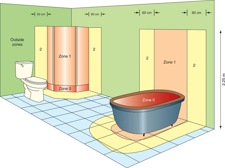
Figure 3.94 Bathroom zone dimensions. (Any window recess is in zone 2.)
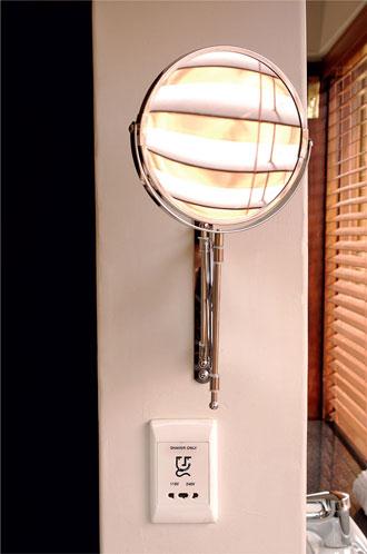
Figure 3.95 Zone 2 shaver socket.
Zone 1 – water heaters, showers and shower pumps and SELV fixed equipment may be installed in zone 1. The electrical equipment must have at least IPX4 protection against water splashing from any direction. If the electrical equipment may be exposed to water jets from, for example, commercial cleaning equipment, then the electrical equipment must have IPX5 protection.
Zone 2 – luminaires and fans, and equipment from zone 1 plus shaver units to BS EN 60742 may be installed in zone 2. The electrical equipment must be suitable for installation in that zone according to the manufacturer’s instructions and have at least IPX4 protection against splashing or IPX5 protection if commercial cleaning is anticipated.
Outside
Zones – appliances are allowed plus accessories except socket outlets unless the location containing the bath or shower is very big and the socket outlet can be installed at least 3 m horizontally beyond the zone 1 boundary (IET Regulation 701.512.3) and has additional RCD protection (IET Regulation 701.411.3.3).
If underfloor heating is installed in these areas it must have an overall earthed metallic grid or the heating cable must have an earthed metallic sheath, which is connected to the protective conductor of the supply circuit (IET Regulation 701.753).
Key fact
Unlike Wales, Part P of the building regulations in England no longer considers kitchens as special locations.
Supplementary equipotential bonding
Modern plumbing methods make considerable use of non-metals (PTFE tape on joints, for example). Therefore, the metalwork of water and gas installations cannot be relied upon to be continuous throughout. The IET Regulations describe the need to consider additional protection by supplementary equipotential bonding in situations where there is a high risk of electric shock (e.g. in kitchens and bathrooms) (IET Regulation 415.2).
In kitchens, supplementary bonding of hot and cold taps, sink tops and exposed water and gas pipes is only required if an earth continuity test proves that they are not already effectively and reliably connected to the protective equipotential bonding, having negligible impedance, by the soldered pipe fittings of the installation. If the test proves unsatisfactory, the metalwork must be bonded using a single-core copper conductor with PVC green/yellow insulation, which will normally be 4 mm2 for domestic installations but must comply with IET Regulation 543.1.1.
In rooms containing a fixed bath or shower, supplementary equipotential bonding conductors must be installed to reduce to a minimum the risk of an electric shock unless the following two conditions are met:
1 all bathroom circuits are protected by a fuse or CB plus a 30 mA RCD; and
2 the bathroom is located in a building with a main protective equipotential bonding system in place (IET Regulation 701.415.2) as shown in Fig 3.106.
 Top tip
To attest to the effectiveness of supplementary bonding, a low resistance measurement must be made from the earthing terminal to the extraneous pipes in the bathroom: reading to be < 0.05Ω.
Supplementary equipotential bonding conductors in domestic premises will normally be of 4 mm2 copper with PVC insulation to comply with IET Regulation 543.1.1 and must be connected between all exposed metalwork (e.g. between metal baths, bath and sink taps, shower fittings, metal waste pipes and radiators).
The bonding connection must be made to a cleaned pipe, using a suitable bonding clip. Fixed at, or near, the connection must be a permanent label saying ‘Safety electrical connection – do not remove’ (IET Regulation 514.13.1).
Segregation of circuits
Where an installation comprises a mixture of low-voltage and very low-voltage circuits such as mains lighting and power, fire alarm and telecommunication circuits, they must be separated or segregated to prevent electrical contact (IET Regulation 528.1).
Key fact
Band I and II circuits can be enclosed together, provided that the cables are insulated to the highest voltage present.
For the purpose of these regulations various circuits are identified by one of two bands as follows:
• Band I: telephone, radio, bell, call and intruder alarm circuits, emergency circuits for fire alarm and emergency lighting.
• Band II: mains voltage circuits.
When Band I circuits are insulated to the same voltage as Band II circuits, they may be drawn into the same compartment. When trunking contains rigidly fixed metal barriers along its length, the same trunking may be used to enclose cables of the separate bands without further precautions, provided that each band is separated by a barrier, as shown in Fig. 3.96. Multi-compartment PVC trunking cannot provide band segregation since there is no metal screen between the bands. This can only be provided in PVC trunking if screened cables are drawn into the trunking.
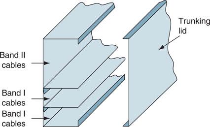
Figure 3.96 Segregation of cables in trunking.
Assessment criteria 2.1
Specify the operating principles of overcurrent protection devices
Assessment criteria 4.11
Verify the fault current capacities of protective devices
Protection against overcurrent
Excessive current may flow in a circuit as a result of an overload or a short circuit.
An overload or overcurrent is defined as a current that exceeds the rated value in an otherwise healthy circuit. A short-circuit is an overcurrent resulting from a fault of negligible impedance. For example, connecting a live part to earth.
Overload currents usually occur in a circuit because the circuit is being misused or overloaded, or because it was badly designed in the first place.
Key fact
An overload is not a fault but a situation where too much current is put on an otherwise healthy circuit. Please note that RCDs will not operate during an overload.
Short-circuits usually occur as a result of an accident that could not have been predicted before the event. An overload may result in currents of two or three times the rated current flowing in the circuit, while short-circuit currents may be hundreds of times greater than the rated current. In both cases, the basic requirement for protection is that the circuit should be interrupted quickly and the circuit isolated safely, before the fault causes a temperature rise or mechanical effect which might damage the insulation, connections, joints and terminations of the circuit conductors and their surroundings. (IET Regulations 131). If the device used for overload protection is also capable of breaking a prospective short-circuit current safely, then one device may be used to give protection from both faults (IET Regulation 432.1). Devices that offer protection from overcurrent are:
• semi-enclosed fuses manufactured to BS 3036;
• cartridge fuses manufactured to BS 88–3: 2010 (used to be 1361);
• high-breaking capacity fuses (HBC fuses) manufactured to BS 88–2: 2010;
• circuit breakers manufactured to BS EN 60898.
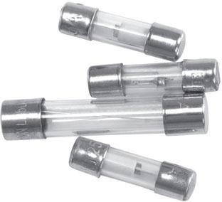
Figure 3.97 Certain cartridge fuses use a glass tube, which allows visibility of the fusing wire.
Overcurrent protection
The consumer’s mains equipment must provide protection against overcurrent, that is, a current exceeding the rated value (IET Regulation 430.3). Fuses provide overcurrent protection when situated in the live conductors; they must not be connected in the neutral conductor. Circuit-breakers may be used in place of fuses, in which case the circuit-breaker may also provide the means of isolation, although a further means of isolation is usually provided so that maintenance can be carried out on the circuit-breakers themselves.
When selecting a protective device we must give consideration to the following factors:
• the prospective fault current;
• the circuit load characteristics;
• the current-carrying capacity of the cable;
• the disconnection time requirements for the circuit.
Definition
Any protective device be it a fuse or circuit-breaker is placed in the circuit to protect the circuit conductors.
Definition
An overload current can be defined as a current that exceeds the rated value in an otherwise healthy circuit.
The essential requirements for a device designed to protect against overcurrent are:
• it must operate automatically under fault conditions;
• have a current rating matched to the circuit design current;
• have a disconnection time which is within the design parameters;
• have an adequate fault breaking capacity;
• be suitably located and identified.
We will look at these requirements below.
A short circuit is an overcurrent resulting from a fault of negligible impedance connected between conductors.
As already defined, an overcurrent may be an overload current, or a short-circuit current. An overload current is when we ask too much of a circuit and therefore we exceed the rated value in an otherwise healthy circuit. A short-circuit is an overcurrent resulting from a fault when, for example, the line conductors come in contact with the neutral, basically removing the load from the circuit. This is known as the prospective short circuit current.
Given that a short-circuit current may be hundreds of times greater than the rated current there is a need to ascertain if a protective device and switch gear can withstand this short circuit capacity without damage, and is known as ascertaining breaking capacity. In fact, there are two separate values defined: Icn which is marked within a rectangle on the device or through use of the letter M as in M6, which indicates the maximum value of current that the protective device can interrupt safely but may be un-useable thereafter. There is also Ics, which is known as the in-service short-capacity, which indicates the maximum fault current that can be interrupted without loss of performance.
In all cases, the basic requirement for protection is that any fault current is interrupted quickly and the circuit is isolated safely before the fault current causes a temperature rise or mechanical effects, which might damage the insulation, connections, joints and terminations of the circuit conductors or their surroundings (IET Regulations 131). It is well worth reminding the reader therefore that this process ties into the earthing system which forms one method of bringing about fault protection. In other words, any exposed conductive part must be connected to the earthing system via a CPC, whose resistance must be low in value so that the fault current is high. This means that the protective device will operate and disconnect the circuit quickly within the required time.
The selected protective device should have a current rating that is not less than the full load current of the circuit but which does not exceed the cable current rating. The cable is then fully protected against both overload and short-circuit faults (IET Regulation 435.1). Devices that provide overcurrent protection are:
• High breaking capacity (HBC) fuses to BS 88-2: 2010. These are for industrial applications having a maximum fault capacity of 80 kA.
• Cartridge fuses to BS 88-3: 2010. These are used for a.c. circuits on industrial and domestic installations having a fault capacity of about 30kA.
• Cartridge fuses to BS 1362. These are used in 13 A plug tops and have a maximum fault capacity of about 6 kA.
• Semi-enclosed fuses to BS 3036. These were previously called rewirable fuses and are used mainly on domestic installations. Their fault capacity is small compared to other protective devices rated at about 4 kA.
• CBs to BS EN 60898. These are circuit-breakers (CBs) which may be used as an alternative to fuses for some installations. The British Standard includes ratings up to 100 A and maximum fault capacities of 9 kA. They are graded according to their instantaneous tripping currents – that is, the current at which they will trip within 100 ms. This is less than the time taken to blink an eye.
Definition
By definition a fuse is the weakest link in the circuit, Under fault conditions it will melt when an overcurrent flows, protecting the circuit conductors from damage.
Assessment criteria 2.3
Specify the advantages and limitations of different types of overcurrent protection devices
Semi-enclosed fuses (BS 3036)
The semi-enclosed fuse consists of a fuse wire, called the fuse element, secured between two screw terminals in a fuse carrier. The fuse element is connected in series with the load and the thickness of the element is sufficient to carry the normal rated circuit current. When a fault occurs an overcurrent flows and the fuse element becomes hot and melts or ‘blows’.
This type of fuse is illustrated in Fig. 3.98. The fuse element should consist of a single strand of plain or tinned copper wire having a diameter appropriate to the current rating of the fuse. This type of fuse was very popular in domestic installations, but less so these days because of its disadvantages.
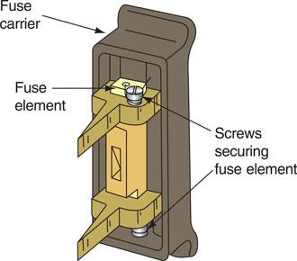
Figure 3.98 A semi-enclosed fuse.
Advantages of semi-enclosed fuses
• They are very cheap compared with other protective devices both to install and to replace.
• There are no mechanical moving parts.
• It is easy to identify a ‘blown’ fuse.
Disadvantages of semi-enclosed fuses
• The fuse element may be replaced with wire of the wrong size either deliberately or by accident.
• The fuse element weakens with age due to oxidization, which may result in a failure under normal operating conditions.
• The circuit cannot be restored quickly since the fuse element requires screw fixing.
• They have low breaking capacity since, in the event of a severe fault, the fault current may vaporize the fuse element and continue to flow in the form of an arc across the fuse terminals.
• They are not guaranteed to operate until up to twice the rated current is flowing.
• There is a danger from scattering hot metal if the fuse carrier is inserted into the base when the circuit is faulty.
Cartridge fuses (BS 88-3: 2012 (previously BS 1361))
The cartridge fuse breaks a faulty circuit in the same way as a semi-enclosed fuse, but its construction eliminates some of the disadvantages experienced with an open-fuse element. The fuse element is encased in a glass or ceramic tube and secured to end-caps that are firmly attached to the body of the fuse so that they do not blow off when the fuse operates. Cartridge fuse construction is illustrated in Fig. 3.99.
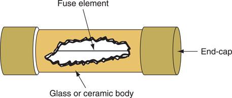
Figure 3.99 Cartridge fuse.
With larger size cartridge fuses, lugs or tags are sometimes brazed on the end-caps to fix the fuse cartridge mechanically to the carrier. They may also be filled with quartz sand to absorb and extinguish the energy of the arc when the cartridge is brought into operation.
Advantages of cartridge fuses
• They have no mechanical moving parts.
• The declared rating is accurate.
• The element does not weaken with age.
• They have small physical size and no external arcing, which permits their use in plug tops and small fuse carriers.
• Their operation is more rapid than semi-enclosed fuses. Operating time is inversely proportional to the fault current, so the bigger the fault current the quicker the fuse operates.
• They are easy to replace.
• Larger valves have bolt-hole fixings.
Disadvantages of cartridge fuses
• They are more expensive to replace than fuse elements that can be rewired.
• They can be replaced with an incorrect cartridge.
• The cartridge may be shorted out by wire or silver foil in extreme cases of bad practice.
• It is not possible to see if the fuse element is broken.
Circuit-breakers (BS EN 60898)
The disadvantage of all fuses is that when they have operated they must be replaced. A circuit-breaker overcomes this problem since it is an automatic switch that opens in the event of an excessive current flowing in the circuit and can be closed when the circuit returns to normal.
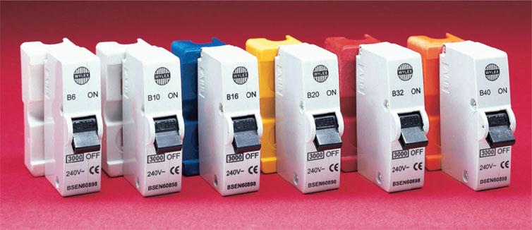
Figure 3.100 CBs – B Breaker, fits Wylex standard consumer unit (courtesy of Wylex).
A circuit breaker of the type shown in Fig. 3.100 incorporates a thermal and magnetic tripping device. The load current flows through the thermal and the electromagnetic devices in normal operation but under overcurrent conditions they activate and trip the circuit-breaker.
The circuit can be restored when the fault is removed by pressing the ON toggle. This latches the various mechanisms within the CB and ‘makes’ the switch contact. The toggle switch can also be used to disconnect the circuit for maintenance or isolation, or to test the CB for satisfactory operation.
Advantages of circuit-breakers
• They have factory-set operating characteristics.
• Tripping characteristics and therefore circuit protection is set by the installer.
• They can distinguish between an overload and short circuit
• The circuit protection is difficult to interfere with.
• The circuit is provided with discrimination.
• A faulty circuit may be quickly identified by the position of the on/off toggle.
• A faulty circuit may be easily and quickly restored.
• The supply may be safely restored by an unskilled operator.
Disadvantages of CBs
• They are relatively expensive but look at the advantages to see why they are so popular these days.
• They contain mechanical moving parts and therefore require regular testing to ensure satisfactory operation under fault conditions.
Additional protection: RCDs
While not an overcurrent protective device, the residual current device is a device that provides earth leakage protection.
When it is required to provide the very best protection from electric shock and fire risk, earth fault protection devices are incorporated into the installation. The object of the regulations concerning these devices (411.3.2 to 411.3.3) is to remove an earth fault current very quickly, less than 0.4 s for all final circuits not exceeding 32 A, and limit the voltage that might appear on any exposed metal parts under fault conditions to not more than 50 V. They will continue to provide adequate protection throughout the life of the installation even if the earthing conditions deteriorate. This is in direct contrast to the protection provided by overcurrent devices, which require a low-resistance earth loop impedance path.
The regulations recognize RCDs as ‘additional protection’ in the event of failure of the provision for basic protection, fault protection or carelessness by the users of the installation (IET Regulation 415.1.1).
Key fact
• RCDs only operate with earth faults; they will not operate if a short circuit occurs.
• RCDs are known as additional protection because they cannot provide sole protection of a circuit and are therefore additional to a circuit protective device.
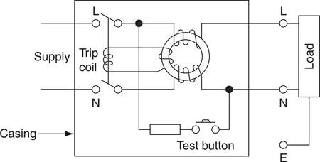
Figure 3.101 Construction of an RCD.
The basic circuit for a single-phase RCD is shown in Fig. 3.101. The load current is fed through two equal and opposing coils wound on to a common transformer core. The phase and neutral currents in a healthy circuit produce equal and opposing fluxes in the transformer core, which induces no voltage in the tripping coil. However, if more current flows in the line conductor than in the neutral conductor as a result of a fault between live and earth, an out-of-balance flux will result in an e.m.f. being induced in the trip coil, which will open the double-pole switch and isolate the load. Modern RCDs have tripping sensitivities between 10 and 30 mA, and therefore a faulty circuit can be isolated before the lower lethal limit to human beings (about 50 mA) is reached.
Consumer units are now supplied that incorporate one or more RCDs, as shown in the On-Site Guide Figs 3.6.3.
Wherever RCDs are installed a label shall be fixed near to each RCD stating ‘The device must be tested 6 monthly’. (IET Regulation 514.12.2) Note In the 17th Edition the test period was three monthly.
RCBO
A residual current operated circuit-breaker with integral overcurrent protection (RCBO) provides protection against overload and/or short-circuits. RCBOs give the combined protection of a CB and an RCD in one device.
In a split-board consumer unit, about half of the total number of final circuits is protected by the RCD. A fault on any one final circuit will trip out all of the RCD protected circuits, which may cause inconvenience.
The RCBO gives the combined protection of a CB plus RCD for each final circuit so protected and, in the event of a fault occurring only the faulty circuit is interrupted. This arrangement is shown in the On-Site Guide at Fig 3.6.3 (i)
Finally, it should perhaps be said that a foolproof method of giving protection to people or animals who simultaneously touch both live and neutral has yet to be devised. The ultimate safety of an installation depends upon the skill and experience of the electrical contractor and the good sense of the user.
Assessment criteria 2.2
Distinguish the application of overcurrent protection devices
The selection of protective devices will depend on various factors, including:
1 Prospective fault current
2 Circuit load characteristics
3 The rated short circuit capacity of a protective device must not be less than the prospective fault current at the point it is installed. The On-Site Guide provides Table 7.2.7 (i) where it lists the rated short circuit capacities of overcurrent protective devices.
• BS 3036 semi-enclosed (rewireable) fuses are still permitted, however cartridge fuses are preferred.
• Cartridge fuses to BS1361 (now replaced by BS 88-3) can be found and used in domestic or similar premises.
• Cartridge fuses to BS 88 are classified as:
– gG general application;
– gM motor circuits;
– aM motor circuits.
Characteristics of Circuit Breakers (CBs)
CB Type B to BS EN 60898 will trip instantly at between three and five times its rated current and is also suitable for domestic and commercial installations.
CB Type C to BS EN 60898 will trip instantly at between five and ten times its rated current. It is more suitable for highly inductive commercial and industrial loads such as fluorescent lights.
CB Type D to BS EN 60898 will trip instantly at between 10 and 25 times its rated current. It is suitable for motors, welding and X-ray machines where large inrush currents may occur.
Assessment criteria 4.10
Verify discrimination between protective devices
Effective coordination of protective devices
IET Regulation 536 tells us that in the event of a fault occurring on an electrical installation only the protective device nearest to the fault should operate, leaving other healthy circuits unaffected. A circuit designed in this way would be considered to have effective co-ordination IET Regulation 536. The speed of operation of the protective device increases as the rating decreases.
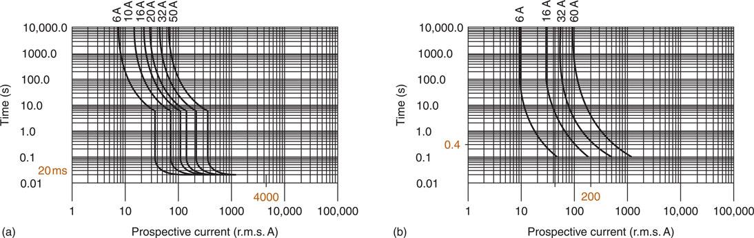
Figure 3.102 Time/current characteristics of (a) a Type B MCB to BS EN 60898 and (b) semi-enclosed fuse to BS 3036.
This can be seen in Fig. 3.102(b). A fault current of 200 A will cause a 16 A semienclosed fuse to operate in about 0.1 s, a 32 A semi-enclosed fuse in about 0.4 s and a 60 A semi-enclosed fuse in about 5.0 s. If a circuit is arranged as shown in Fig. 3.103 and a fault occurs on the appliance, effective co-ordination will be achieved because the 16 A fuse will operate more quickly than the other protective devices if they were, for example, all semi-enclosed type fuses with the characteristics shown in Fig. 3.102(b).
In general, when overcurrent protective devices are connected in series, only the device which the designer intended to operate, should operate. This is usually the device closest to the point at which the overcurrent occurs. In the case of Fig 3.103 a fault on the appliance will operate the 16 amp fuse protecting it, leaving the other circuits intact.
Security of supply, and therefore effective co-ordination, is an important consideration for an electrical designer and is also a requirement of the IET Regulations 536.
When existing installations are updated or modified it may be necessary to include additional protective devices, for example, in the following cases:
• when circuit conductors are reduced for instance 2.5mm2 down to 1.5mm2;
• when wiring systems are changed for instance from mineral insulated to SWA;
• when a single circuit feed splits to supply multiple circuits.
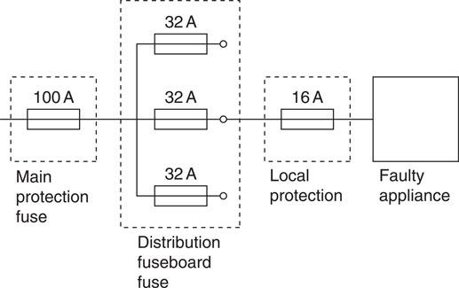
Figure 3.103 Effective co-ordination of the protective devices.
In these types of circumstances co-ordination does not necessary occur with smaller rated devices operating first. Protective devices allow a certain amount of energy through before they operate, therefore circuit designers would look at each device characteristics and specifically the energy limiting class number (1, 2 or 3) to ensure that a given amount of current will operate a certain device and not the others. Designers can also use time/current characteristics of protective devices included in BS 7671. For example, see Fig 3A4 on page 370 of the Regs book for a Type B circuit breaker.
These time current characteristics, which are designed specifically for a particular protective device, include inserted tables which denote the minimum amount of current required to isolate a circuit. For instance, a 20 A Type B circuit breaker requires 100 A to ensure safe disconnection. These values can therefore be used to ensure that co-ordination occurs.
Co-ordination is also a consideration regarding additional protection and the use of RCDs. Consideration must therefore be given to the position of RCDs that are upstream and downstream within the circuit, so that the tripping requirement of the upstream RCD is greater than the downstream, thus avoiding inadvertent isolation of the circuit.
Assessment criteria 3.1
Distinguish earthing systems
Assessment criteria 3.2
Interpret the requirements for protection against electric shock
Electrical supplies and earthing arrangements
We know from earlier chapters in this book that using electricity is one of the causes of accidents in the workplace. Using electricity is a hazard because it has the potential to cause harm. Therefore, the provision of protective devices in an electrical installation is fundamental to the whole concept of the safe use of electricity in buildings. The electrical installation as a whole must be protected against overload or short circuit, and the people using the building must be protected against the risk of shock, fire or other risks arising from their own misuse of the installation or from a fault. The installation and maintenance of adequate and appropriate protective measures is a vital part of the safe use of electrical energy. I want to look at protection against an electric shock by both basic and fault protection, at protection by equipotential bonding and automatic disconnection of the supply.
Let us first define some of the words we will be using. Chapter 54 of the IET Regulations describes the earthing arrangements for an electrical installation. It gives the following definitions:
Earth – the conductive mass of the earth whose electrical potential is taken as zero.
Earthing – the act of connecting the exposed conductive parts of an installation to the main protective earthing terminal of the installation.
Bonding conductor – a protective conductor providing equipotential bonding. Bonding – the linking together of the exposed or extraneous metal parts of an electrical installation.
Circuit protective conductor (CPC) – a protective conductor connecting exposed conductive parts of equipment to the main earthing terminal. This is the green and yellow insulated conductor in twin and earth cable.
Exposed conductive parts – this is the metalwork of an electrical appliance or the trunking and conduit of an electrical system that can be touched because they are not normally live, but which may become live under fault conditions.
Extraneous conductive parts – this is the structural steelwork of a building and other service pipes such as gas, water, radiators and sinks. They do not form a part of the electrical installation but may introduce a potential, generally earth potential, to the electrical installation.
Shock protection – protection from electric shock is provided by basic protection and fault protection.
Basic protection – this is provided by the insulation of live parts in accordance with Section 416 of the IET Regulations.
Fault protection – this is provided by protective equipotential bonding and automatic disconnection of the supply (by a fuse or CB) in accordance with IET Regulations 411.3.
Protective equipotential bonding – this is equipotential bonding for the purpose of safety.
Basic protection and fault protection
The human body’s movements are controlled by the nervous system. Very tiny electrical signals travel between the central nervous system and the muscles, stimulating operation of the muscles, which enable us to walk, talk and run; and remember that the heart is also a muscle.
If the body becomes part of a more powerful external circuit, such as the electrical mains, and current flows through it, the body’s normal electrical operations are disrupted. The shock current causes unnatural operation of the muscles and the result may be that the person is unable to release the live conductor causing the shock, or the person may be thrown across the room. The current which flows through the body is determined by the resistance of the human body and the surface resistance of the skin on the hands and feet.
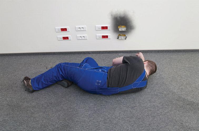
Figure 3.104 An electric shock can throw people across the room, often with devastating results.
This leads to the consideration of exceptional precautions where people with wet skin or wet surfaces are involved, and the need for special consideration in bathroom installations.
Two types of contact will result in a person receiving an electric shock. Direct contact with live parts involves touching a terminal or line conductor that is actually live. The regulations call this basic protection (131.2.1). Indirect contact results from contact with an exposed conductive part such as the metal structure of a piece of equipment that has become live as a result of a fault. The regulations call this fault protection (131.2.2).
The touch voltage curve in Fig. 3.105 shows that a person in contact with 230 V must be released from this danger in 40 ms if harmful effects are to be avoided. Similarly, a person in contact with 400 V must be released in 15 ms to avoid being harmed.
In installations operating at normal mains voltage, the primary method of protection against direct contact (basic protection) is by insulation. All live parts are enclosed in insulating material such as rubber or plastic, which prevent contact with those parts. The insulating material must, of course, be suitable for the circumstances in which they will be used and the stresses to which they will be subjected. Other methods of basic protection include the provision of barriers or enclosures which can only be opened by the use of a tool, or when the supply is first disconnected. Protection can also be provided by fixed obstacles such as a guardrail around an open switchboard or by placing live parts out of reach as with overhead lines.
Fault protection
Protection against indirect contact, called fault protection (IET Regulation 131.2.2), is achieved by connecting exposed conductive parts of equipment to the main earthing terminal of the installation as shown in Figs. 3.106, 3.108. In Chapter 13 of the IET Regulations we are told that where the metalwork of electrical equipment may become charged with electricity in such a manner as to cause danger, that metalwork will be connected with earth so as to discharge the electrical energy without danger.
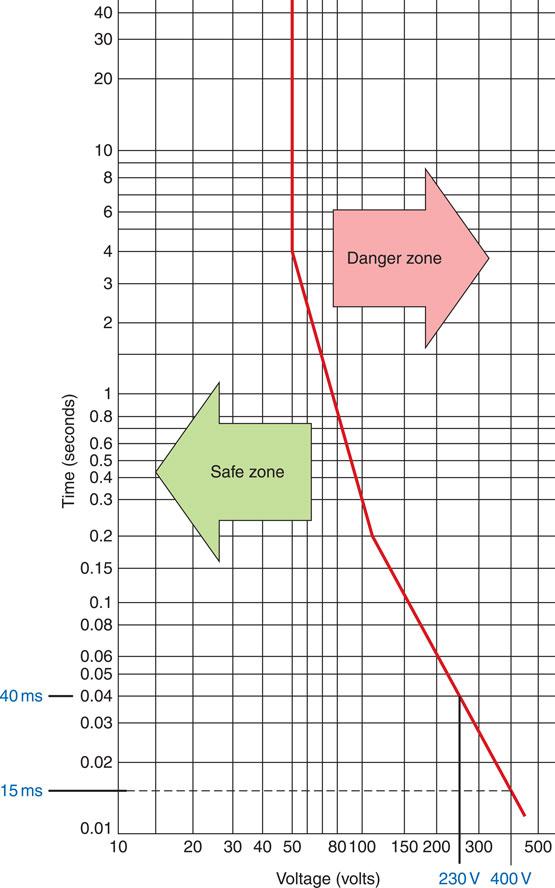
Figure 3.105 Touch voltage curve.
The application of equipotential bonding is one of the important principles for safety.
There are five methods of protection against contact with metalwork that has become unintentionally live, that is, indirect contact with exposed conductive parts recognized by the IET Regulations. These are:
1 Protective equipotential bonding coupled with automatic disconnection of the supply.
2 The use of Class II (double insulated) equipment.
3 The provision of a non-conducting location.
4 The use of earth free equipotential bonding.
5 Electrical separation.
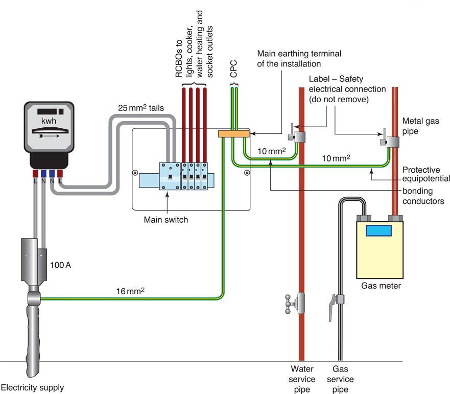
Figure 3.106 Cable sheath earth supply (TN-S systems) showing earthing and bonding arrangements.
Methods 3 and 4 are limited to special situations under the effective supervision of trained personnel.
Method 5, electrical separation, is little used but does find an application in the domestic electric shaver supply unit, which incorporates an isolating transformer.
Method 2, the use of Class II insulated equipment, is limited to single pieces of equipment such as tools used on construction sites, because it relies upon effective supervision to ensure that no metallic equipment or extraneous earthed metalwork enters the area of the installation.
The method that is most universally used in the United Kingdom is, therefore, Method 1 – protective equipotential bonding coupled with automatic disconnection of the supply.
This method relies upon all exposed metalwork being electrically connected together to an effective earth connection. Not only must all the metalwork associated with the electrical installation be so connected, that is, conduits, trunking, metal switches and the metalwork of electrical appliances, but also IET Regulation 411.3.1.2 tells us to connect the extraneous metalwork of water service pipes, gas and other service pipes and ducting, central heating and air conditioning systems, exposed metallic structural parts of the building and lightning protective systems to the main protective earthing terminal. In this way the possibility of a voltage appearing between two exposed metal parts is removed. Protective equipotential bonding is shown in Figs 3.106, 3.108.
Key fact
When carrying out earthing and bonding activities:
• use a suitable bonding clamp;
• connect to a cleaned pipe;
• make sure all connections are tight;
• fix a label ‘Safety Electrical Connection’ close to the connection.
IET regulation 514.13.
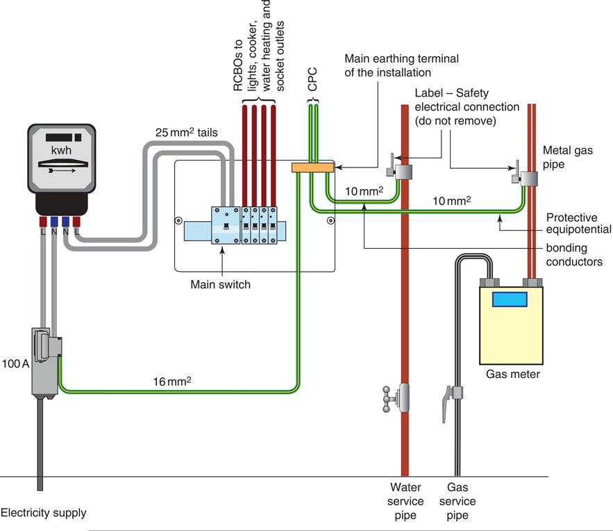
Figure 3.107 Protective multiple earth supply (TN-C-S system) showing earthing and bonding arrangements.
Figures 3.106, 3.108 show protective equipotential bonding conductors connected to gas and water supplies. This is necessary if the incoming supplies are metallic. However, the 18th Edition of the IET Regulations at 411.3.1.2 tells us that metal pipes entering a building having an insulated section at their entry to the building need not be connected to the equipotential bonding of the installation.
However, the premises gas, water and electricity supplies must be bonded on the consumers hard metal pipe work, at the point of entry to the building as shown in Figures 3.106, 3.108 of this book, and figures 2.1 (i) to 2.1 (iii) of the On Site Guide (IET Regulation 544.1.2).
You will see in Figs 3.106, 3.108 that a consumer unit is being used for the control and distribution of electrical energy, however recent fire statistics have shown that a large number of domestic fires involved plastic consumer units as the source of the fire. Consumer units are often located at the entrance or exit door of the home or under the stairs, raising the possibility that a fire starting as a result of faulty wiring could block the emergency exit route. Regulation 421.1.201 of the 18th Edition of the Regulations now requires that consumer units be manufactured from non-combustible material, for example, metal, or be enclosed in a non-combustible enclosure.
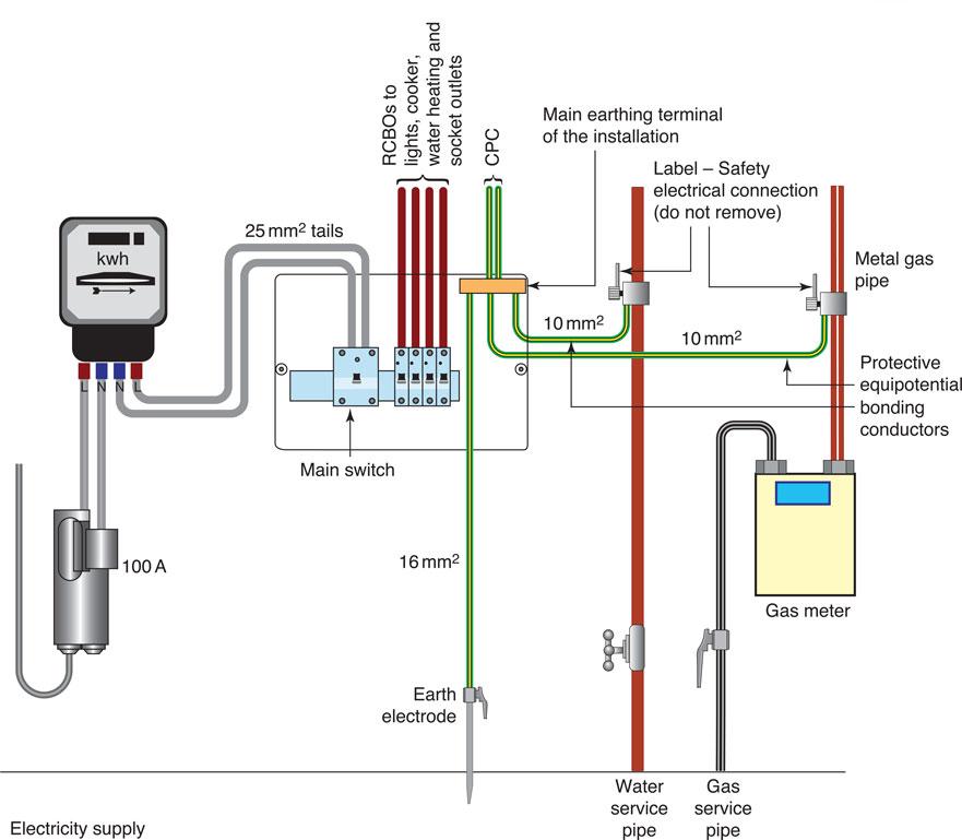
Figure 3.108 No earth provided supply (TT systems) showing earthing and bonding arrangements.
The 18th Edition of the Regulations at 421.1.7 now also recommends the use of arc fault detection devices (AFDD) as a means of providing additional protection against fire caused by arc faults in AC final circuits.
Supply system earthing arrangements
The British government agreed on 1 January 1995 that the electricity supplies in the United Kingdom would be harmonized with those of the rest of Europe. Thus the voltages used previously in low-voltage supply systems of 415 and 240 V have become 400 V for three-phase supplies and 230 V for single-phase supplies. The Electricity Supply Regulations 1988 have also been amended to permit a range of variation from the newly declared nominal voltage. From January 1995 the permitted tolerance is the nominal voltage +10% and −6%. Previously it was +/− 6%. This gives a voltage range of 216-253 V for a nominal voltage of 230 V and 376-440 V for a nominal voltage of 400 V (IET Regulations Appendix 2).
It is further proposed that the tolerance levels will be adjusted to +10% of the declared nominal voltage. All EU countries will have to adjust their voltages to comply with a nominal voltage of 230 V single-phase and 400 V three-phase. The supply to a domestic, commercial or small industrial consumer’s installation is usually protected at the incoming service cable position with a 100 A BS 88-3 high breaking capacity (HBC) fuse. Other items of equipment at this position are the energy meter and the consumer’s distribution unit, providing the protection for the final circuits and the earthing arrangements for the installation.
The supply earthing
Five earthing systems are described in the definitions but only the TN-S, TN-C-S and TT systems are suitable for public supplies. A system consists of an electrical installation connected to a supply. Systems are classified by a capital letter designation.
The supply earthing arrangements are indicated by the first letter, where T means one or more points of the supply are directly connected to earth and I means the supply is not earthed or one point is earthed through a fault-limiting impedance.
The installation earthing
The installation earthing arrangements are indicated by the second letter, where T means the exposed conductive parts are connected directly to earth and N means the exposed conductive parts are connected directly to the earthed point of the source of the electrical supply.
The earthed supply conductor
The earthed supply conductor arrangements are indicated by the third letter, where S means a separate neutral and protective conductor and C means that the neutral and protective conductors are combined in a single conductor.
Cable sheath earth supply (TN-S system)
This is one of the most common types of supply system to be found in the United Kingdom where the electricity companies’ supply is provided by underground cables. The neutral and protective conductors are separate throughout the system. The protective earth conductor (PE) is the metal sheath and armour of the underground cable, and this is connected to the consumer’s main earthing terminal. All exposed conductive parts of the installation, gas pipes, water pipes and any lightning protective system are connected to the protective conductor via the main earthing terminal of the installation. These arrangements are shown in Figs 3.109, 3.113
(PME) Protective multiple earthing supply (TN-C-S system)
This type of underground supply is becoming increasingly popular to supply new installations in the United Kingdom. It is more commonly referred to as protective multiple earthing (PME). The supply cable uses a combined protective earth and neutral (PEN) conductor. At the supply intake point a consumer’s main earthing terminal is formed by connecting the earthing terminal to the neutral conductor. All exposed conductive parts of the installation, gas pipes, water pipes and any lightning protective system are then connected to the main earthing terminals. Thus phase to earth faults are effectively converted into phase to neutral faults. These arrangements are shown in Figs. 3.109, 3.111.
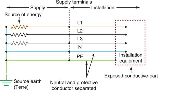
Figure 3.109 TN-S system.
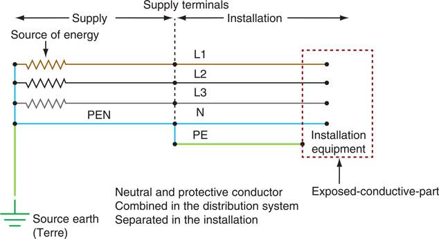
Figure 3.110 TN-C-S system (PME).
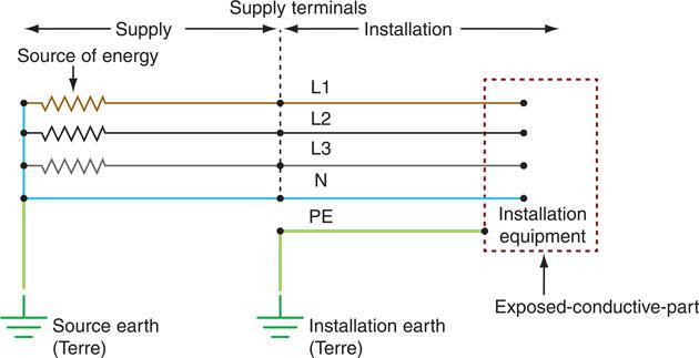
Figure 3.111 TT system.
No earth provided supply (TT system)
This is the type of supply more often found when the installation is fed from overhead cables. The supply authorities do not provide an earth terminal and the installation’s CPCs must be connected to earth via an earth electrode provided by the consumer. Regulation 542.2.3 lists the type of earth rod, earth plates or earth tapes recognized by BS 7671. An effective earth connection is sometimes difficult to obtain and in most cases a residual current device (RCD) is provided when this type of supply is used. The arrangement is shown in Fig. 3.108 and 3.111 which show the layout of a typical domestic service position for these supply systems. They show circuits protected by RCBOs. The use of RCBOs will minimize inconvenience because, in the event of a fault occurring, only the faulty circuit will disconnect. However, alternative consumer unit arrangements using CBs and RCDs are shown in the On-Site Guide at Section 3.6.3. The TN-C and IT systems of supply do not comply with the supply regulations and therefore cannot be used for public supplies. Their use is restricted to private generating plants and for this reason I shall not include them here, but they can be seen in Part 2 of the IET Regulations.
Assessment criteria 3.3
Select suitably sized protective conductors in accordance with BS 7671
The general layout of a domestic supply is shown clearly within section 2 of the On-Site Guide including the size of the main earthing conductor (16 mm2) and main equipotential bonding conductors (10 mm2). However, these values are in respect to both the earthing system in use, whether they are buried and protected and the size of the meter tails. All such details are specified in Chapter 54 of BS 7671 or Section 4 of the On-Site Guide. Another consideration regarding protective conductors comes with thermal constraint since Table 54.7 of Chapter 54 specifies that protective conductors and line conductors up to ≤ 16 mm must be the same. However, when PVC flat profile cabling is used aside from 1 mm2, all other size of conductors include a smaller sized CPC. Thermal constraint therefore is a calculation to ensure that the size of CPC used can safely carry any prospective fault current. This is covered in greater detail in learning outcome 4.
Part 1 of Chapter 13, section 132 of the IET Regulations details the fundamental principles for the design of an electrical installation. Let us now look at electrical design in some detail as required by the EAL syllabus and Section 132 of the IET Regulations.
Electrical systems design – the process
The designer of an electrical installation must ensure that the design meets the requirements of the IET Wiring Regulations for electrical installations and any other regulations that may be relevant to a particular installation. The designer may be a professional technician or engineer whose job is to design electrical installations for a large contracting firm. In a smaller firm, the designer may also be the electrician who will carry out the installation to the customer’s requirements. The designer of any electrical installation is the person who interprets the electrical requirements of the customer within the regulations, identifies the appropriate types of installation, the most suitable methods of protection and control and the size of cables to be used.
Definition
The designer of an electrical installation is the person who interprets the electrical requirements of the customer within the regulations.
Chapter 13, Section 132 of the regulations gives us 16 regulations that make up the design process. The headings are as follows:
Energy Efficiency – a new Part 8 of the Regulations
The 18th Edition of the Regulations gives us a new Appendix 17, Energy Efficiency. It is intended that this new Appendix will become a new Part 8 in future Amendments to the regulations. The new Appendix provides recommendations for the design and erection of electrical installations. All new electrical installation design, and modifications to existing installations must continue to meet the required levels of safety and capacity which we will calculate in this section, but must NOW ALSO optimise electrical efficiency, providing the lowest levels of electricity consumption.
The new Appendix considers design and maintenance from the context of improving the efficiency of the electrical installation. There is a change of emphasis in this new section, to incorporate energy efficiency into the electrical installation design as a prerequisite, and not just as an aspiration.
The standard makes it clear that any measure taken to make the electrical installation more efficient, must not compromise the safety of any occupants, property or livestock, and that much of this appendix will not apply to domestic and similar installations.
Let us now consider some of the design process regulations.
132.1 General
In the introduction, the IET Regulation tells us that the electrical installation must be designed to provide for:
• the protection of people, livestock and property; and
• to meet the intended use required of the installation.
132.2 Characteristics of the supply
One of the first considerations for the designer is to determine the nature or characteristics of the supply and the earthing arrangements. Inspection of the existing supply or by requesting details from the supply distributor will be necessary to determine:
• the supply voltage;
• the type of supply and earthing arrangements, that is TN-S, TN-C-S or TT system;
• the value of the earth fault loop impedance, Ze for the supply;
• the location of the supply.
For new electrical installations or for significant alterations to existing ones, the Electricity Safety Quality and Continuity Regulations require the electricity distributor to install the cut out and meter in a ‘safe location’ where they can be mechanically protected and safely maintained. In compliance with this ‘safe location’ requirement the electricity distributor and installer may in some areas be required to take account of the risk of flooding. To comply, the distributors’ equipment and the installation’s consumer unit or fuse boards must be installed above the flood level. Upstairs power and lighting circuits and downstairs lighting should be installed above the flood level. Upstairs and downstairs circuits should have separate protective devices. Consumer units or fuse boards must be generally accessible for use by responsible persons in the household. They should not be installed where young people might interfere with them (IET Guide to the Building Regs 2.1 and 3.1).
Figure 3.112 The electricity grid power supply mostly travels along conductors supported by pylons.
Upon request, the supply distributor will give the following information for a typical domestic supply:
• single phase a.c. supply;
• maximum value of the distributors protective device is 100 A;
• the normal voltage will be 230 V to earth;
• frequency 50 cycles per second;
• the maximum or worst case external earth fault loop impedance (Ze) will be
– 0.8 ohms for cable sheath (TN-S) supplies;
– 0.35 ohms for PME (TN-C-S) supplies;
– for no earth provided (TT) supplies. The value given by the distributor for the earth electrode resistance at the supply transformer is usually 21 ohms. The resistance of the consumer’s installation earth electrode should be as low as possible but a value exceeding 200 ohm might not be stable (IET On-Site Guide 1.1);
• the maximum or worst case prospective fault current at the origin of the installation will normally be 16 kA. If a protective device is to operate safely, its rated short-circuit capacity must be not be less than the prospective fault current at the point where it is installed. It is recommended that the electrical installation design should be based upon the maximum fault current value provided by the distributor and not on measured values. Except for London and some other major city centres, the maximum fault current for 230 V single phase supplies up to 100 A will not exceed 16 kA (IET On-Site Guide Table 7.2.1(i)).
These characteristics are very important, but equally is the process behind the selection and erection of the wiring and associated equipment including enclosures.
We will now look at the electrical design process by first examining how much current the installation requires.
Assessment criteria 4.1
Determine the design current
Assessment criteria 4.2
Select a suitably rated protective device
132.3 The nature of demand
The designer must identify the number of circuits required and the expected load on these circuits. The total current demand of any final circuit is estimated by adding together the current demands of all points of utilization such as socket and lighting points and equipment outlets. This involves using the main formula for power for an electrician P = V × I.
Final circuit current demand
In this chapter we will only look at straightforward household installations but the same principles apply to shops, hotels and guest houses. All of these premises are dealt with in Appendix A of the On-Site Guide. Let us begin by looking at the current demand to be assumed for points of utilization given in Table A1 of the On-Site Guide and shown here at Table 3.10.
Example 1
Calculate the current demand of a 7.36kW electric shower connected to the 230 V mains supply.
The power P = 7.36kW or 7360 watts
The voltage V = 230 volts
The power factor = cos ϕ = 1 for a resistive load
Now power = V I cos ϕ
Example 2
Calculate the current demand of an electric cooker comprising
A hob with 4 2.5kW rings = 10kW
A main oven rated at 2kW and = 02kW
A grill/top oven rated at 2kW = 02kW total 14kW
The cooker control unit incorporates a 13A socket outlet
So the total capacity of the cooker is 14kW at 230 volts
And cos ϕ = 1 for a resistive load
From Table 3.10 above we take the first 10A of the rated current, plus 30% of the remainder plus 5A if the control unit incorporates a socket outlet.
Therefore a 32 amp CB would adequately protect this circuit.
Example 3
A lighting circuit consists of 10 points. Calculate the current demand.
From Table 3.10 we must assume a minimum of 100 watts per point.
Therefore a 5 amp fuse or a 6 amp CB would protect this circuit if ordinary GLS lamps were being used. However, if extra-low voltage or discharge lighting is connected to this circuit and protected by a type ‘B’ CB we must take account of the inrush current which occurs at switch-on and sometimes causes unwanted or nuisance tripping of the CB. To avoid this, the circuit will be adequately protected by a 10 amp CB.
Example 4
The kitchen work surface of a domestic kitchen is to be illuminated by 10 30 watt fluorescent tubes fixed to the underside of the cupboards above the work surface. Calculate the current demand of this circuit.
From Table 3.10 the demand is taken as the lamp watts multiplied by 1.8
Therefore a 5 amp fuse or a 6 amp CB would protect this circuit.
Example 5
Calculate the current demand of a 3kW immersion heater installed in a 30-litre water storage vessel. We know from Table 3.10 that we should take the British Standard rated current for a water heater such as this, or we can calculate the current rating as before.
A 15 amp fuse or 16 amp CB will protect this circuit. We also know from Appendix H5 of the On-Site Guide that water heaters fitted to vessels in excess of 15 litres must be supplied on their own separate circuit.
Diversity between final circuits
The current demand of a circuit is the current taken by that circuit over a period of time, say 30 minutes. Some loads make a constant demand all the time they are switched on. A 100 watt light bulb will make a constant current demand of (100 watts ÷ 230 volts) 0.43 amperes whenever it is switched on. However, an automatic washing machine is made up of a variable speed motor, a pump and a water heater all controlled by a programmer. The washer load will not be constant for the whole time it is switched on, but will vary depending upon the wash cycle. Diversity makes an allowance on the basis that not all of the load or connected items will be in use at the same time. The design would be wasteful if it did not take advantage of the diversity between different loads. Let us now look at diversity as it applies to a straightforward household installation but the same principles will apply to shops, offices, business premises and hotels. Appendix A of the On-Site Guide gives the diversity for all these different types of premises.
The allowances for diversity shown in Table A2 of the On-Site Guide are for very specific situations and can only provide guidance. The diversity allowances for lighting circuits should be applied to ‘items of equipment’ connected to the consumer unit at a rate of 66%. However, standard power circuit arrangements for households, as described in Appendix H of the On-Site Guide, can be applied to the rated current of the overcurrent protective device for the circuit.
The diversity allowance for standard socket outlet circuits is 100% of the largest circuit, plus 40% of all other power circuits. It is important to ensure that the consumers unit is of sufficient rating to take the total load connected without the application of diversity.
Example 6
Calculate the current demand, including diversity, for a six-way consumer unit comprising the following circuits in a domestic dwelling.
Circuit 1. A lighting circuit comprising 10 points as described in Example 3, previously having a maximum demand of 4.35A and protected by a 6 amp CB. (66% diversity allowed for lighting circuits)
Circuit 2. A lighting circuit comprising 10, 30 watt fluorescents as described in Example 4, previously having a maximum demand of 2.3A and protected by a 6 amp CB. (Again 66% diversity allowed.)
Circuit 3. A thermostatically controlled 3kW immersion heater as described in Example 5, previously having a maximum demand of 13.04A and protected by a 16 amp CB. (No diversity allowed)
Circuit 4. A ring circuit of 13A socket outlets installed in accordance with Section H of the On-Site Guide and protected by a 32 amp CB. (This is one of the largest socket circuits, so, no diversity allowed.)
Circuit 5. A radial circuit of 13A socket outlets installed in accordance with section H of the On-Site Guide and protected by a 32 amp CB. (40% diversity allowed.)
Circuit 6. A radial circuit of 13A socket outlets installed in accordance with section H of the On-Site Guide and protected by a 20 amp CB. (40% diversity allowed.)
Table A2 line 9 of the On-Site Guide tells us that for standard household circuits as described in Appendix H of the OSG, (for example ring and radial circuits) the allowable diversity is to be calculated as follows: 100% of the current demand of the largest circuit plus 40% of the current demand of every other standard socket outlet circuit. The diversity for all lighting circuits is 66%. The IET Design Guide follows this format, so let us now consider our own Example 6.
From the question
Circuit 1 has a maximum demand of |
4.35 amps |
Circuit 2 has a maximum demand of |
2.34 amps |
Circuit 3 has a maximum demand of |
13.04 amps |
Circuit 4 has a maximum demand of |
32.00 amps |
Circuit 5 has a maximum demand of |
32.00 amps |
Circuit 6 has a maximum demand of |
20.00 amps |
We can see from the above that the largest circuit in the consumers unit is 32 amps, so let us nominate circuit 4 as the largest circuit and apply diversity to all other standard final circuits.
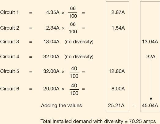
To summarize:
• Dividing the power rating of the load by the working voltage tells us the amount of basic current the circuit requires. This basic current is known as the design current lb.
• Certain circuits are not on all the time and are given an allowance which when applied reduces the current demand and will therefore allow us to use a smaller circuit conductor. This is known as applying diversity (Appendix A of the On-Site Guide).
Once Ib has been established BS 7671 (Chapter 43) states that there must exist a certain coordination between the conductor and the nominal value of the protective device In. The first of these being that:
In other words the protective device needs to be the same value as the design current or bigger. The designer also needs to look at the size of conductor required and the manner in which the circuit cable is to be installed and this is known as establishing the reference method.
Assessment criteria 4.3
Establish the installation method reference
Assessment criteria 4.4
Apply appropriate rating factors
Assessment criteria 4.5
Determine the minimum current carrying capacity of live conductors
Assessment criteria 4.6
Establish if the voltage drop is acceptable
132.6 Conductor size calculations
The size of a cable to be used for an installation depends upon:
• the current rating of the cable under defined installation conditions; and
• the maximum permitted drop in voltage as defined by IET Regulation 525. The current carrying capacity of a conductor is known as Iz and the designer is also influenced by a second circuit coordination if there is a requirement for the circuit to withstand overloads as well as a short circuit. The requirement is this:
In other words, the current carrying capacity of the cable Iz must be equal to or greater than the nominal value In of the protective device.
Once this has been established there are other factors that influence the current rating:
1 Design current: cable must carry the full load current.
2 Type of cable: PVC, MICC, copper conductors or aluminium conductors.
3 Installed conditions: clipped to a surface or installed with other cables in a trunking.
4 Surrounding temperature: cable resistance increases as temperature increases and insulation may melt if the temperature is too high.
5 Type of protection: for how long will the cable have to carry a fault current?
IET Regulation 525 states that the drop in voltage from the supply terminals to the fixed current-using equipment must not exceed 3% for lighting circuits and 5% for other uses of the mains voltage. That is, a maximum of 6.9 V for lighting and 11.5 V for other uses on a 230 V installation. The volt drop for a particular cable may be found from:
The factor is given in the tables of Appendix 4 of the IET Regulations and Appendix F of the On-Site Guide. They are also given in Table 3.13 in this book. The cable rating, denoted It, may be determined as follows:
The cable rating must be chosen to comply with IET Regulation 433.1. The correction factors that may need applying are given below as:
Ca – the ambient or surrounding temperature correction factor, which is given in Tables 4B1 and 4B2 of Appendix 4 of the IET Regulations or Table F1 of the On-Site Guide. They are also shown in Table 3.11 of this book.
Cg – the grouping correction factor given in Tables 4C1 to 4C5 of the IET Regulations and Table F3 of the On-Site Guide.
Cf – the 0.725 correction factor to be applied when semi-enclosed fuses protect the circuit as described in item 5.1.1 of the preface to Appendix 4 of the IET Regulations and Appendix F of the On-Site Guide.
Ci – the correction factor to be used when cables are enclosed in thermal insulation. For example by examining Table F2 of the On-Site Guide we can determine that where the cable is totally surrounded by thermal insulation over a length greater than 0.5m we must apply a factor of 0.5.
Where the cable is totally surrounded over a short length, the appropriate factor given in Table 52.2 of the IET Regulations or Table F2 of the On-Site Guide should be applied.
Note: A cable should preferably not be installed in thermal insulations.
Having calculated the cable rating, It the smallest cable should be chosen from the appropriate table which will carry that current. This cable must also meet the voltage drop (IET Regulation 525) and this should be calculated as described earlier. When the calculated value is less than 3% for lighting and 5% for other uses of the mains voltage the cable may be considered suitable. If the calculated value is greater than this value, the next larger cable size must be tested until a cable is found that meets both the current rating and voltage drop criteria.
Table 3.11 Ambient temperature correction factors
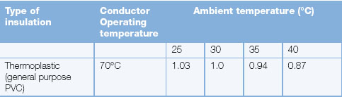
Example
A house extension has a total load of 6kW installed some 18 m away from the mains consumer unit for lighting. A PVC insulated and sheathed twin and earth cable will provide a sub-main to this load and be clipped to the side of the ceiling joists over much of its length in a roof space which is anticipated to reach 35°C in the summer and where insulation is installed up to the top of the joists. Calculate the minimum cable size if the circuit is to be protected by a type B CB to BS EN 60898. Assume a TN-S supply; that is, a supply having a separate neutral and protective conductor throughout.
Let us solve this question using only the tables given in the On-Site Guide. The tables in the regulations will give the same values, but this will simplify the problem because we can refer to Tables 3.11, 3.12 and 3.13 in this book which give the relevant On-Site Guide tables.
Nominal current setting of the protection for this load In = 32 A.
The cable rating It is given by:
The correction factors to be included in this calculation are:
Ca ambient temperature; as shown in Table 3.11 the correction factor for 35°C is 0.94.
Cg grouping factors need not be applied.
Cf, since protection is by CB no factor need be applied.
Ci thermal insulation demands that we assume installed Method A in Table 3.12
The design current is 26.09A and we will therefore choose a 32A CB for the nominal current setting of the protective device, In.
From column 2 in Table 3.12, a 10 mm cable, having a rating of 43A, is required to carry this current.
Now test for volt drop: from Table 3.13 the volt drop per ampere per metre for a 10 mm cable is 4.4 mV from column 3. So the volt drop for this cable length and load is equal to:
Since this is less than the maximum permissible value for a lighting circuit of 6.9 V, a 10 mm cable satisfies the current and drop in voltage requirements when the circuit is protected by a CB. This cable is run in a loft that gets hot in summer and has thermal insulation touching one side of the cable. We must, therefore, use installed reference Method A of Table 3.12. If we were able to route the cable under the floor, clipped direct or in conduit or trunking on a wall, we may be able to use a 6 mm cable for this load. You can see how the current-carrying capacity of a cable varies with the installed method by looking at Table 3.12. Compare the values in column 2 with those in column 6. When the cable is clipped direct on to a wall or surface the current rating is higher because the cable is cooler. If the alternative route was longer, you would need to test for volt drop before choosing the cable. These are some of the decisions the electrical contractor must make when designing an installation which meets the requirements of the customer and the IET Regulations.
If you are unsure of the standard fuse and CB rating of protective devices, you can refer to Fig. 3A4 of Appendix 3 of the IET Regulations.
Key fact
Volt drop
Maximum permissible volt drop on 230V supplies:
• 3% for lighting – 6.9 V
• 5% for other uses −11.5V
IET Regulation 525 and Table 4Ab Appendix 4.
Cable size for standard domestic circuits
Section 3.2 of Chapter 3 of the IET Electrical Installation Design Guide tells us that the basic design intent is to use standard final circuits wherever possible to avoid repeated design. Provided earth fault loop impedances are below 0.35 ohms for TN-C-S supplies and 0.8 ohms for TN-S supplies the standard circuits can be used as the basis of all final circuits. Appendix 4 of the IET Regulations (BS 7671) and Appendix F of the IET On-Site Guide contain tables for determining the current carrying capacities of conductors, which we looked at in the last section. However, for standard domestic circuits, Table 3.14 gives a guide to cable size. In this table, I am assuming a standard 230 V domestic installation, having a sheathed earth or PME supply terminated in a 100 A HBC fuse at the mains position. Final circuits are fed from a consumer unit, having Type B CB protection and wired in PVC insulated and sheathed cables with copper conductors having a grey thermoplastic PVC outer sheath or a white thermosetting cable with LSF (low smoke and fume properties). I am also assuming that the surrounding temperature throughout the length of the circuit does not exceed 30°C and the cables are run singly and clipped to a surface.
Table 3.12 Current carrying capacity of cables
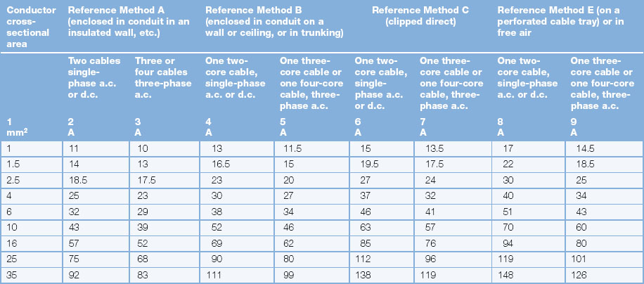
Table 3.14 Cable size for standard domestic circuits
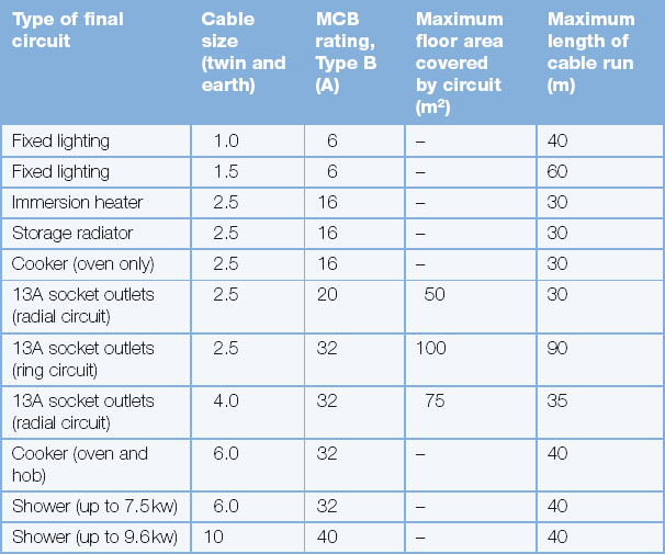
Assessment criteria 4.7
Verify if disconnection times have been achieved
Assessment criteria 4.9
Establish the maximum disconnection times for different circuits
The general earthing arrangements has already been covered in learning outcome 3.1 but the principle behind earth fault loop impedance will now be covered.
Earth fault loop impedance Zs
In order that an overcurrent protective device can operate successfully it must meet the required disconnection times of IET Regulation 411.3.2.2, that is, final circuits not exceeding 32 A shall have a disconnection time not exceeding 0.4 s. To achieve this, the earth fault loop impedance value measured in ohms must be less than those values given in Appendix B of the On-Site Guide and Tables 41.2 and 41.3 of the IET Regulations.
The actual fault path to earth is known as the earth loop impedance, impedance being used when we combine an inductor and resistance. Very simply it can be thought of as alternating resistance and opposes any rate of change in an alternating signal such as the mains which operates at a frequency of 50 Hz. The mains, of course, comes from a sub-station and is stepped down through the use of a transformer. The transformer therefore uses mutual induction and R1 and R2 are the line and CPC, respectively. Therefore by combining both the inductor within the transformer and the conductors we bring about the term impedance.
The value of the earth fault loop impedance may be verified by means of an earth fault loop impedance test as described in Chapter 4 of this book. The formula is:
Here ZE is the impedance of the supply side of the earth fault loop. The actual value will depend upon many factors: the type of supply, the ground conditions, the distance from the transformer, etc. The value can be obtained from the area electricity companies, but typical values are 0.35 Ω for TN-C-S (protective multiple earthing, PME) supplies and 0.8 Ω for TN-S (cable sheath earth) supplies as described a little earlier in this chapter. Also in the above formula, R1, is the resistance of the line conductor and R2 is the resistance of the earth conductor. The complete earth fault loop path is shown in Fig. 3.113.
Values of R1 + R2 have been calculated for copper and aluminium conductors and are given in Table I1 of the On-Site Guide as shown in Table 3.15.
The maximum permitted value given in Table 41.3 of the IET Regulations for a 20 A CB protecting a socket outlet is 2.19 Ω as shown by Table 3.16.
Safety first
A very important change that came about through Amendment 3 of BS 7671 (2015) is that earth loop impedance values were lowered.
The circuit earth fault loop impedance is less than this value and therefore the protective device will operate within the required disconnection time of 0.4 s. The value of the earth fault loop impedance can be measured using the test described in IET Regulation 619.2 and compared with the tables of 41.42 and 41.3 of the IET Regulations and Appendix B of the On-Site Guide. The test is also described in Chapter 4 of this book.
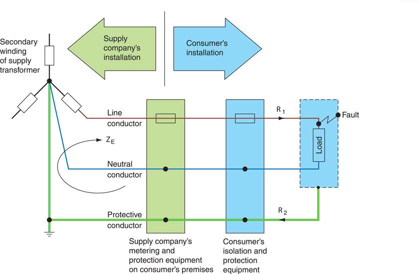
Figure 3.113 Earth fault loop path for a TN-S system.
Example 1
A 20 A radial socket outlet circuit is wired in 2.5 mm2 PVC cable incorporating a 1.5 mm2 CPC. The cable length is 30 m installed in an ambient temperature of 20°C and the consumer’s protection is by 20 A CB Type B to BS EN 60898. The earth fault loop impedance of the supply is 0.5 Ω. Calculate the total earth fault loop impedance ZS, and establish that the value is less than the maximum value permissible for this type of circuit.
We have:
From the value given in Table I1 of the On Site Guide and also shown in Table 3.15, a 2.5 mm phase conductor with a 1.5 mm protective conductor has an (R1 + R2) value of 19.51 × 10⁻³ Ω/m.
However, under fault conditions, the temperature and therefore the cable resistance will increase. To take account of this, we must multiply the value of cable resistance by the factor given in Table I3 of the On-Site Guide. In this case the factor is 1.20 and therefore the cable resistance under fault conditions will be:
The total earth fault loop impedance is therefore:
Table 3.16 Maximum earth fault loop impedance Zs (Ω) when the overcurrent protective device is an MCB Type B to BS EN 60898

The maximum permitted value given in the IET Regulations for a 20 amp circuit breaker protecting a socket outlet is 2.19 ohms as shown in Table 3.16. The circuit earth fault loop impedance in the example is 1.202 ohms, which is less than 2.19 ohm, and therefor the protective device will operate within the required disconnection time of 0.4 seconds. The value of earth fault loop impedance can be measured using the test described in IET Regulation 643.7.3 and in Chapter 4 of this book.
Assessment criteria 4.8
Evaluate thermal constraints
Protective conductor size
The CPC forms an integral part of the total earth fault loop impedance, so it is necessary to check that the cross-section of this conductor is adequate. If the cross-section of the CPC complies with Table 54.7 of the IET Regulations, there is no need to carry out further checks. Where line and protective conductors are made from the same material, Table 54.7 tells us that:
• for line conductors equal to or less than 16 mm2, the protective conductor should equal the line conductor;
• for line conductors greater than 16 mm2 but less than 35 mm2, the protective conductor should have a cross-sectional area of 16 mm2;
• for line conductors greater than 35 mm2, the protective conductor should be half the size of the line conductor.
However, where the conductor cross-section does not comply with this table, then the formula given in IET Regulation 543.1.3 must be used:
where
S = cross-sectional area in mm2
I = value of maximum fault current in amperes
t = operating time of the protective device
k = a factor for the particular protective conductor
Finally, as has been stated previously, a foolproof method of giving protection to people or animals who simultaneously touch both live and neutral has yet to be devised. The ultimate safety of an installation depends upon the skill and experience of the electrical contractor and the good sense of the user.
Given the complexity of the process involved it will now be covered again step by step with reference to both BS 7671 and the On-Site Guide. To assist with referencing, each specific element is signposted below to indicate where certain information can be found:
Example 1
A 230 V ring main circuit of socket outlets is wired in 2.5 mm single PVC copper cables in a plastic conduit with a separate 1.5 mm CPC. An earth fault loop impedance test identifies Zs as 1.15 Ω. Verify that the 1.5 mm CPC meets the requirements of IET Regulation 543.1.3 when the protective device is a 30 A semi-enclosed fuse.
t = maximum operating time of the protective device for a circuit not exceeding 32 A is 0.4 s from IET Regulation 411.3.2.2. From Fig. 3A2(a) in Appendix 3 of the IET Regulations you can see that the time taken to clear a fault of 200 A is about 0.4 s
k =115 (from Table 54.3)
A 1.5 mm2 CPC is acceptable since this is the nearest standard-size conductor above the minimum cross-sectional area of 1.10 mm2 found by calculation.
Example 2
A TN supply feeds a domestic immersion heater wired in 2.5 mm2 PVC insulated copper cable and incorporates a 1.5 mm2 CPC. The circuit is correctly protected with a 16A semi-enclosed fuse to BS 3036. Establish by calculation that the CPC is of an adequate size to meet the requirements of IET Regulation 543.1.3. The characteristics of the protective device are given in IET Regulation Fig. 3A2(a) of Appendix 3.
For final circuits less than 32A the maximum operating time of the protective device is 0.4 s. From Fig. 3A2(a) of Appendix 3 it can be seen that a current of about 90A will trip the 15A fuse in 0.4 s. The small insert table on the top right of Fig. 3A2(a) of Appendix 3 of the IET Regulations gives the value of the prospective fault current required to operate the device within the various disconnection times given.
So, in this case the table states that 90A will trip a 16A semi-enclosed fuse in 0.4s
The CPC of the cable is greater than 0.49 mm2 and is therefore suitable. If the protective conductor is a separate conductor, that is, it does not form part of a cable as in this example and is not enclosed in a wiring system as in Example 1, the cross-section of the protective conductor must be not less than 2.5 mm2 where mechanical protection is provided or 4.0 mm2 where mechanical protection is not provided in order to comply with IET Regulation 544.2.3.
Design from first principles
• Design current: Power/Volts
• Protective device (rating available): On-Site Guide Appendix B
• Installation method: On-Site Guide Table 7.1 (ii)
• Circuit correction factors and formula: On-Site Guide Appendix F
• Select cable size (current carrying capacity): On-Site Guide, Table F6
• Volt drop formula: On-Site Guide Appendix F
• Confirm volt drop: On-Site Guide, Table F4 (ii) or F6
• Confirm shock protection is met through loop impedance values: Appendix B Table B6
• Thermal constraint formula from BS 7671: Part 5, Chapter 54.
Extracting design data
Answers are in the back of the book.
1 State how we calculate design current.

2 State the rule regarding In (size of protective device) in relation to design current.

3 Where in the On-Site Guide can you find a list of protective device ratings normally available?

4 Write out the formula used when calculating the tabulated current-carrying capacity of the selected cable.

5 When using a BS 3036 fuse (Cf Correction) what correction factor should we use during the cable calculation stage?

6 What correction factor should we use for 3 PVC/PVC twin core cables that are grouped together and installed using Reference Method C? (Look in Appendix F.)

7 What correction factor should we use for any type of cable that is surrounded by thermal insulation for 0.5 m?

8 What correction factor should we use for a PVC/PVC twin core cable that is exposed to an ambient temperature of 35°C?

9 If the protective device of a circuit is rated at 20 A and Ca (0.8) and Ci (0.65) corrections have to be applied, calculate It: the tabulated current carrying capacity.

10 With reference to Appendix F of the On-Site Guide, what ambient temperature does not need correcting?

11 What is the correct description of Reference (Installation) Method C?

12 Given the reference method above and using Table F6 of the On-Site Guide, determine what size cable is required to carry 47 A.

13 State the tolerances for voltage drop regarding lighting and power. (Look in Appendix F of the On-Site Guide or volt drop in the index.)

14 What is the formula used for calculating voltage drop? (Look in Appendix F of the On-Site Guide or volt drop in the index.)

15 Using Table F6 of the On-Site Guide, the size of cable at step 12, a design current of 27 A, a circuit that is 20 m long, calculate if this circuit complies with the volt drop requirements for a lighting circuit.

16 What do we mean by shock protection?

17 Look in the On-Site Guide and determine the maximum Zs value for a 40 A Type B circuit breaker.

18 Given that this value has been extracted from the On-Site Guide do we have to correct the value by multiplying by 0.8?

19 Given the value above in step 17, if the measured loop impedance value Zs of a circuit is 0.91Ω, what does this mean regarding shock protection?

20 Given the Zs value above calculate the PFC.

21 What do we mean by thermal constraint?

22 A 6 mm2 PVC flat profile cable has a 2.5 mm2 CPC and has a K constant of 115. If the PFC of the circuit is 1.7 KA and the circuit needs to be disconnected in 0.4 s, calculate if the thermal constraint requirement is met.

Design exercise
A 10 kW kiln is to be fed from a domestic consumer unit that is positioned 15m away. The wiring type is PVC/PVC flat profile cable that is clipped direct to the surface and the circuit should be protected by a Type B circuitbreaker. From enquiry the DNO state that the PFC is 329 A and Zs has been measured at 0.7 Ω. The cable is grouped with one other circuit in an area with an ambient temperature of 35°C.
Work out the following:
Answers are in the back of the book.
1 Design current (Ib).

2 Size of protective device (In).

3 Having established any correction factors, calculate the tabulated current carrying capacity (It).

4 Size of cable required.

5 Is the volt drop OK?

6 Is the shock protection OK?

7 Is the thermal constraint OK?

Assessment criteria 5.1
Specify the health and safety requirements in establishing a safe working environment
The Health and Safety at Work Act 1974 was passed as a result of recommendations made by the Royal Commission and, therefore, the Act puts legal responsibility for safety at work on both the employer and employee.
Figure 3.114 It is the duty of the employer to ensure adequate health and safety systems have been put in place.
In general terms, the employer must put adequate health and safety systems in place at work and the employee must use all safety systems and procedures responsibly.
In specific terms the employer must:
• provide a Health and Safety Policy Statement if there are five or more employees;
• display a current employer’s liability insurance certificate as required by the Employers’ Liability (Compulsory Insurance) Act 1969;
• report certain injuries, diseases and dangerous occurrences to the enforcing authority such as the Health & Saftey Executive;
• provide adequate first aid facilities;
• provide PPE;
• provide information, training and supervision to ensure staffs’ health and safety;
• provide adequate welfare facilities;
• put in place adequate precautions against fire, provide a means of escape and means of fighting fire;
• ensure plant and machinery are safe and that safe systems of operation are in place;
• ensure articles and substances are moved, stored and used safely;
• make the workplace safe and without risk to health by keeping dust, fumes and noise under control.
In specific terms the employee must:
• take reasonable care of his/her own health and safety and that of others who may be affected by what they do;
• cooperate with his/her employer on health and safety issues by not interfering with or misusing anything provided for health, safety and welfare in the working environment;
• report any health and safety problem in the workplace to, in the first place, a supervisor, manager or employer.
Assessment criteria 5.2
Specify how to ensure that worksites are correctly prepared
Safe system of work
Employers’ responsibilities are specifically defined through the Management of Health and Safety at Work Regulations 1999, which detail how employers must systematically examine the workplace, the work activity and the management of safety, ensuring that a safe system of work is in place.
Therefore a safe system of work (SSOW) is simply a means of ensuring that employees operate in a safe and controlled environment. In the electrical installation industry, a safe system of work is underpinned by three primary elements: risk assessments, method statements and permit to work systems.
They are designed to:
• Identify hazards and exposure to the hazards (risk): formal risk assessment
• Detail how a procedure will be carried out: method statement
• Work in hazardous areas has to be authorized: permit to work
Let us look at each in detail.
Definition
• A hazard is something that might cause harm.
• A risk is the chance that harm will be done.
The process of risk assessment for the electrical installation industry would include:
• working at heights;
• using electrical power tools;
• falling objects;
• working in confined places;
• electrocution and personal injury;
• working with ‘live’ equipment;
• using hire equipment;
• manual handling – pushing – pulling – lifting;
• site conditions – falling objects – dust – weather – water – accidents and injuries.
Aside from considering personnel, the same consideration should be given to the property and any animals and livestock including reflecting on the safest route to and from a site or specific location. Any particular hazardous activity would need to be controlled through a permit to work, which instils structure through a formal authorization pro forma, but also requires the person undertaking the job declaring that they are fully conversant with the task in hand. A properly defined method statement will detail how a procedure or job will be carried out referencing any risk assessments, special tools, access equipment as well as how any waste material will be disposed of.
All these procedures make up a safe system of work but knowing where they are stored and how to gain access to them is also important. This information should be shared with all employees including apprentices.
Assessment criteria 5.3
Clarify the preparations that should be completed before electrical installation work starts
Assessment criteria 5.4
Outline how to check for any pre-existing damage to customer/client property
Assessment criteria 5.5
State the actions that should be taken if pre-existing damage to customer/client property is identified
Assessment criteria 5.6
Specify methods for protecting the fabric and structure of the property before and during installation work
To make the work area safe before starting work, and during work activities, it may be necessary to:
• use barriers or tapes to screen off potential hazards;
• place warning signs as appropriate;
• inform those who may be affected by any potential hazard;
• use a safe isolation procedure before working on live equipment or circuits;
• obtain any necessary permissions or ‘Permits to Work’ before work begins.
Get into the habit of always working safely and being aware of the potential hazards around you when working. If pre-existing damage to the structure or fabric of the building is observed by the electrical team upon arrival at the site, then a decision must be taken, before the electrical work commences, as to who will be responsible for the repairs. If the building structure is damaged, it may be unsafe to commence the electrical work before remedial work has been undertaken.
If the building fabric or structure is damaged as a result of the electrical work activities, for example where conduits or trunking pass through the floor or walls, then it must be made good by the electrical team or their representative.
The electrical team must always be respectful of the customers property and contents when carrying out their electrical activities. This might involve laying dust sheets over some items, or moving others to a safe area while work is carried out, or wearing plastic protectors over your shoes so that carpets are not damaged.
Always be polite to the customer. The customer will probably see more of the electrican and electrical trainee than the managing director of the company, and therefore the image presented by them to the customer will be assumed to reflect the company policy. You are therefore your companies most important representative at that time, and indirectly, it is the customer who pays your wages.
Finally, when the job is completed, clean up and dispose of any waste material responsibly. This is an important part of your companies ‘good customer relationship’ with the client. We also know that we have a ‘duty of care’ for the waste that we produce as an electrical company.
Test your knowledge
When you have completed the questions check out the answers at the back of the book.
Note: more than one multiple-choice answer may be correct.
Learning outcome 1
1 Which of the following statutory requirements is most important when planning an installation?
a. Health and Safety Act 1974
b. BS 7671 Wiring Regulations
c. Building Regulation 2000
d. Electricity at Work Regulation 1989.
2 Which of the following is an important consideration regarding the movement of vehicles and adequate flood lighting?
a. safe access and egress
b. training facilities
c. adequate welfare facilities
d. a safety policy.
3 According to the Electricity at Work Act 1989 when can you carry out a ‘live’ repair?
a. only if you are supervised
b. only if you feel that you are ‘competent’ to do so
c. never, you are not allowed to
d. only if you are experienced.
4 As fitted, drawings form part of the:
a. fitting element
b. timetabling element
c. scheduling element
d. completion element.
5 Band 1 and Band 2 cabling can be enclosed in the same enclosure if:
a. they are insulated to the highest voltage present
b. at 90° to each other
c. separated by metal divisions
d. wrapped around each other.
6 What kind of drawing is this?
a. block
b. schematic
c. detail
d. layout.
7 Which document details the duties of employers to employees in providing a safe place of work?
a. IET Wiring Regulations
b. Building Regulations
c. Electricity at Work Regulations
d. Health and Safety at Work Act.
8 Ignoring BS 7671 would most likely cause:
a. an electrical fire
b. a real fire
c. a solid fuel fire
d. a gas fire.
9 Removing all elements of electrical supply to a piece of equipment in order to ensure the safety of those working on it is one definition of:
a. emergency switching
b. functional switching
c. switching for isolation
d. switching for mechanical maintenance.
10 Cutting off the full load electrical supply to a piece of equipment in order to ensure the safety of those working on it is one definition of:
a. emergency switching
b. functional switching
c. switching for isolation
d. switching for mechanical maintenance.
11 The rapid disconnection of the electrical supply to remove or prevent danger is one definition of:
a. emergency switching
b. functional switching
c. switching for isolation
d. switching for mechanical maintenance.
12 Switching electrical equipment in normal service is:
a. emergency switching
b. functional switching
c. switching for isolation
d. switching for mechanical maintenance.
13 Looking at the diagram, the numbers 2, 3 and 4 represent:
a. service meter, meter tails, service fuse
b. service meter, service tails, service fuse
c. service head, meter tails, service fuse
d. service head, service meter, service fuse.
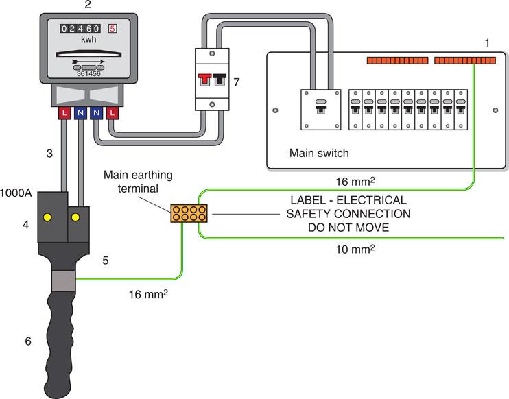
14 The maximum working temperature of PVC/PVC thermoplastic is:
a. 40°C
b. 50°C
c. 60°C
d. 70°C.
15 A light fitting or small spot light must be fixed at an adequate distance from:
a. combustible material
b. combustible walls
c. combustible ceilings
d. combustible joists.
16 Which of the following CANNOT be used as an isolator?
a. switch
b. circuit-breaker
c. semi-conductor (electronic device)
d. switch disconnector.
17 What equipment type does this symbol relate to?
a. Class I
b. Class II
c. Class III
d. Class IV.

18 Three factors that would affect the choice of wiring system would include:
a. temperature
b. animals and plants
c. architect
d. impact damage.
19 Additional protection applies to:
a. cables located within metal enclosures
b. SWA
c. cables embedded >50 mm
d. cables embedded <50 mm
e. special locations.
20 What is the normal size and rating of a lighting cable and protective device?
a. 6 mm2 and 6 A
b. 2.5 mm2 and 6 A
c. 4 mm2 and 6 A
d. 1.5 mm2 and 6 A.
21 Equipment installed in a flour mill needs to be protected against entry of particles such as:
a. dust stopped through IP protection
b. dust stopped through fault protection
c. dust stopped through basic protection
d. dust stopped through additional protection.
22 The protection provided by insulating live parts is called:
a. extraneous conductive parts
b. basic protection
c. exposed conductive parts
d. fault protection.
23 The typical cabling for use in electrical installations in domestic premises would be:
a. SWA
b. PVC/PVC
c. MICC
d. PVC single.
24 Ladder racking is a system for:
a. allowing access to storage racks
b. allowing multiple section extension ladders
c. supporting armoured cables
d. supporting vertical cable basket systems.
25 The type of wiring for use in a factory with high ambient temperatures is:
a. PVC insulated and sheathed
b. PVC insulated cables in galvanized conduit
c. mineral insulated metal sheathed
d. rubber insulated in PVC conduit.
26 Mineral insulated cables are sometimes provided with an overall covering of PVC to:
a. make the cable waterproof
b. protect the cable from sunlight and harmful rays
c. prevent corrosion of the sheath
d. make the cable suitable for use in low ambient temperatures.
27 Where would it be unsuitable to use a rate of rise temperature type heat detector?
a. kitchen
b. dining room
c. hallway
d. garage.
28 An appropriate wiring method for an underground feed to a remote building would be a:
a. metal conduit installation
b. trunking and tray installation
c. PVC cables
d. PVC/SWA cables.
29 An appropriate wiring system for a three-phase industrial installation would be:
a. PVC cables
b. PVC conduit
c. one that meets the requirements of Part 2 of the IET Regulations
d. one that meets the requirements of Part 5 of the IET Regulations.
30 Which wiring system is non-ageing and will ensure that the space between its conductors is kept the same even if flattened?
a. mineral insulated
b. SWA
c. PVC/PVC
d. PVC singles.
31 Which conductor uses the principle of total internal refraction?
a. FP cable
b. fibre-optic
c. mineral insulated
d. PVC/PVC flat profile cable.
32 An alternative to mineral insulated cable that does not require specialized tools would be:
a. FP
b. fibre-optic
c. SWA
d. PVC flex.
33 Which of the following is the most appropriate containment system for industrial high current applications?
a. busbar systems
b. flexible conduit
c. cable tray
d. power track.
34 Which of the following would be most appropriate regarding offsetting the adverse effects of vibration?
a. PVC conduit
b. plastic conduit
c. metal conduit
d. flexible conduit.
35 Which of the following apply to electrical equipment in bathrooms?
a. supplementary bonding
b. index protection
c. earthing
d. additional protection.
36 The maximum floor area that a ring circuit can feed is:
a. 50 m2
b. 75 m2
c. 100 m2
d. 25 m2.
37 Combining a copper cable with an aluminium crimp will result in:
a. increased fault current
b. lower termination resistance
c. dissimilar metal corrosion
d. an explosion.
38 Single core non-armoured cables (apart from bonding conductors) must always be installed:
a. in free air partially covered
b. in conduit or trunking
c. secured with plastic clips
d. in cavity walls.
39 A non-fused spur from a ring may feed:
a. any number of socket outlets
b. any number of fixed appliances
c. one single or twin socket outlet
d. two fixed appliances.
40 An A1 type circuit is associated with:
a. 2.5 mm with 30/32 A fuse
b. 4 mm radial with protective device
c. 1.5 mm radial with 20 A fuse
d. 4 mm ring with 20 A fuse.
41 Ten 1.0 mm single conductors are to be drawn into a conduit. Use Table E3 of the On-Site Guide or Table 3.5 of this book to find the sum of the cable factors for these cables.
a. 16
b. 30
c. 160
d. 300.
42 A three-metre length of conduit with two bends is to contain the ten 1.0 mm cables. Determine the size of conduit required using Table E4 of the On-Site Guide or Table 3.6 of this book.
a. 16 mm
b. 20 mm
c. 25 mm
d. 32 mm.
43 Ten 2.5 mm single conductors are to be drawn into a conduit. Use Table E3 of the On-Site Guide or Table 3.5 of this book to find the sum of the cable factors for these cables.
a. 16
b. 30
c. 160
d. 300.
44 A three-metre length of conduit with two bends is to contain the ten 2.5 mm cables. Determine the size of conduit required using Table E4 of the On-Site Guide or Table 3.6 of this book.
a. 16 mm
b. 20 mm
c. 25 mm
d. 32 mm.
45 Ten 1.5 mm solid PVC cables are to be drawn into trunking. Use Table E5 or Table 3.7 of this book to find the sum of the cable factors for these cables.
a. 80
b. 60
c. 40
d. 20.
46 Ten 2.5 mm solid PVC cables are to be drawn into trunking. Use Table E5 or Table 3.8 of this book to find the sum of the cable factors for these cables.
a. 116
b. 117
c. 118
d. 119.
47 Refer to Tables E1 and E2 of the On-Site Guide and by applying cable and conduit factors, work out how many 4 mm2 cables can be inserted into a 25 mm piece of conduit used in a short straight run.
a. 14
b. 13
c. 12
d. 11.
Learning outcome 2
48 Additional protection is applicable to which of the following?
a. HRC fuse
b. re-wireable fuse
c. RCBO
d. CB.
49 Which of the following will not operate if the line conductor bypasses the load and shorts out against the neutral conductor?
a. HRC fuse
b. RCD
c. RCBO
d. CB.
50 An Industrial welder would need to be protected by:
a. an RCD
b. a Type C circuit-breaker
c. a Type D circuit-breaker
d. a HBC fuse.
51 Coordination of fuses during fault or overload conditions is known as:
a. diversity
b. diverging
c. discrimination
d. deviation.
52 A circuit-breaker has two modes of operation:
a. overload due to thermal effect or short circuit due to a magnetic trip
b. overload due to a magnetic trip or short circuit due to thermal effect
c. overload due to a chemical reaction or short circuit due to a magnetic trip
d. overload due to a thermal trip or chemical reaction due to a magnetic trip.
53 An CB rated at 40 A will trip:
a. only when a short circuit occurs
b. only when an overload occurs
c. when an overload, short circuit or earth fault occurs
d. when 41 A flows through it.
54 An RCD rated at 30 mA will trip:
a. when enough current flows to earth
b. through an earth fault or an overload
c. through an overload, short circuit or earth fault
d. when 30 mA flows.
55 What type of CB is associated with commercial applications especially fluorescent lighting?
a. Type 3
b. Type B
c. Type C
d. Type D.
56 Which device will detect an imbalance between line and neutral, overloads and all types of overcurrent faults?
a. RCD
b. RCBO
c. CB
d. BBC.
57 A fuse protects:
a. the person
b. the switch
c. the cable
d. the load.
58 An RCD protects:
a. the person
b. the switch
c. the cable
d. the load.
59 A value that ensures that a circuit-breaker can withstand a fault current is known as:
a. breaking capacity
b. rating
c. thermal constraint
d. shock protection.
Learning outcome 3
60 Which earthing system is not recommended for petrol stations, caravans and marina pontoons?
a. TN-S
b. TT
c. TNC
d. PME.
61 What is the maximum tabulated value of Ze for a TN-C-S system?
a. 0.8 Ω
b. 0.35 Ω
c. 20 Ω
d. 1.75 Ω.
62 Which earthing system due to the possibility of high Ze values must have additional protection?
a. TN-S
b. TT
c. TN-C-S
d. PME.
63 Which uncommon earthing system is used in hospitals?
a. TN-S
b. IT
c. TNC
d. PME.
64 What supply system uses a PEN conductor?
a. TT
b. TN-S
c. IT
d. TN-C-S.
65 Which earthing system uses an earth electrode and is common in rural areas?
a. TN-S
b. TT
c. TN-C-S
d. PME.
66 The metalwork that does not form part of an electrical installation is called:
a. extraneous conductive parts
b. basic protection
c. exposed conductive parts
d. fault protection.
67 Which of the following is an extraneous conductive part?
a. metal casing of a washing machine
b. metal switch back plate
c. metal casing of an electric motor
d. metal casing of a gas pipe.
68 A current that goes beyond the rated value in an otherwise healthy circuit is one definition of:
a. earthing
b. bonding
c. overload
d. short circuit.
69 What is the maximum disconnection time for TT earthing systems > 32 A?
a. 5 s
b. 1 s
c. 0.2 s
d. 0.4 s.
70 A TN-S earthing system operates through the:
a. earthing electrode
b. PEN conductor
c. supply cable armouring
d. earth itself.
71 Earthing ensures that:
a. a low resistance path, will safeguard that the PFC is high and ensure disconnection is quick
b. a high resistance path, will safeguard that the PFC is high and ensure disconnection is quick
c. a low resistance path, will safeguard that the PFC is low and ensure disconnection is slow
d. a high resistance path, will safeguard that the PFC is low and ensure disconnection is quick.
72 Which of the following symbols represents the external earth loop impedance value?
a. Zx
b. Zs
c. Ze
d. ZT.
73 Which of the following symbols represents the total earth loop impedance value?
a. Zx
b. Zs
c. Ze
d. ZT.
74 The protection provided by equipotential bonding and automatic disconnection of the supply is called:
a. extraneous conductive parts
b. basic protection
c. exposed conductive parts
d. fault protection.
75 Equipotential bonding is carried out to:
a. earth all equipment
b. earth all exposed conductive parts
c. link all extraneous conductive parts
d. stop fuses operating.
76 Which earthing system changes line to earth faults to line to neutral faults?
a. TN-S
b. TT
c. TN-C-S
d. IT.
77 A TN-S earthing system will follow which path?
a. CPC, main earthing terminal, supply armouring back to the transformer
b. earth electrode, CPC, main earthing terminal back to the transformer
c. main earthing terminal, CPC, PEN conductor, back to the transformer
d. CPC, high impedance load, main earthing terminal back to the transformer.
78 Which earthing system has to be earthed itself along its various supply routes?
a. TN-S
b. TT
c. PME
d. IT.
Learning outcome 4
79 What device is described here: The ‘It’ rating must be equal to or above the normal operating current of the circuit?
a. a fuse
b. fuse-board
c. distribution board
d. junction box.
80 What device is described here: The ‘It’ rating must be equal to or above the normal current carrying capacity of the protective device?
a. cable
b. switch
c. load
d. consumer unit.
81 Calculate the total current demand for a domestic lighting circuit if it contains 20 × 100 W GLS filaments and the factor for diversity is 66%.
a. 7.8 A
b. 8.69 A
c. 6 A
d. 5.7 A.
82 When cabling is routed through insulation, the rated:
a. current carrying ability will be decreased
b. current carrying ability will be increased
c. current carrying ability will stay exactly the same
d. current carrying ability will be doubled per metre.
83 If voltage drop in a final circuit is found to be excessive the corrective action is to:
a. limit the time the load is connected
b. boost the voltage through a transformer
c. increase the size of the supply cable
d. decrease the size of the supply cable.
84 When overload and overcurrent protection is necessary which of the following is correct?
a. Ib≥In≥Iz
b. Ib≤In≥Iz
c. Ib≤In≥Iz
d. Ib≥In≤Iz.
85 Which of the following is correct regarding earth fault loop impedance?
a. Zs can be obtained by enquiry
b. Ze can be obtained by enquiry
c. Zs can be obtained by calculation
d. Zs can be obtained by measurement.
86 One disadvantage of using the tabulated values of Ze in the On-Site Guide is:
a. they are hard to read
b. the values could be high
c. the values are unreliable
d. the values could be low.
87 When checking earth loop impedance values which of the following can be used directly without correction?
a. BS 7671
b. wiring regulations
c. GN3
d. On-Site Guide.
88 A domestic cooker rated at a maximum load of 60 A is controlled by a cooker control unit, which does not have a 13 A socket outlet. Using Table A1 of the On-Site Guide, and after allowing for diversity, calculate the design current.
a. 20 A
b. 25 A
c. 18 A
d. 30 A.
89 Correction factors as applied to de-rate system cables are:
a. thermal insulation, grouping, re-wireable fuses and ambient temperature
b. outside insulation, grouping, re-wireable fuses and ambient temperature
c. using SWA cable, grouping, re-wireable fuses and ambient temperature
d. thermal insulation, bare wires, re-wireable fuses and ambient temperature.
90 Which of the following should be recorded regarding the PFC?
a. the prospective short circuit current
b. the prospective earth fault current
c. the highest value PFC at the point of supply
d. the higher value PFC at the furthermost point of the circuit.
91 Why is thermal constraint particularly important when installing with PVC flat profile cable?
a. it is cheap in comparison to other types
b. its CPC is smaller than the live conductors
c. its CPC is bigger than the live conductors
d. its CPC does not come with earthing sleeving.
92 To ensure the effective operation of the overcurrent protective devices, the earth fault loop path must have:
a. a 230 V supply
b. very low resistance
c. fuses or CBs in the live conductor
d. very high resistance.
93 Shock protection ensures that:
a. the protective device operates within a specified time
b. the actual loop impedance values are less than specified
c. the PFC is low enough to operate the protective devices in time
d. the circuit is switched off in time.
94 According to IET Regulation 411.3.2.2 all final circuits not exceeding 32 A in a building supplied with a 230 V TN supply shall have a maximum disconnection time not exceeding:
a. 0.2 s
b. 0.4 s
c. 5.0 s
d. unlimited.
95 The current demand of 10–65 W fluorescent tubes connected to a 230 V supply is:
a. 5.08 mA
b. 5.09 A
c. 150 W
d. 650 W.
96 Use the On-Site Guide (Appendix A) to calculate the assumed current demand of a cooker having 4–3 kW boiling rings and a 2 kW oven connected to a 230 V supply. The cooker control unit includes a socket outlet.
a. 60.86 A
b. 30.26 A
c. 25.25 A
d. 10 A.
97 The total current demand of a lighting circuit in an individual household is calculated to be 5 A. The current demand applying the diversity factor given in Table A2 of the On-Site Guide will be:
a. 3.3 A
b. 3.75 A
c. 4.5 A
d. 5.0 A.
98 The volt drop in mV per ampere per metre of a two-core single-phase 6.0 mm cable as given in Table F5 (ii) of the On-Site Guide or Table 3.13 of this book is:
a. 18
b. 11
c. 7.3
d. 4.4.
99 The volt drop in mV per ampere per metre of a two-core single-phase 10.0 mm cable as given in Table F5 (ii) of the On-Site Guide or Table 3.13 of this book is:
a. 18
b. 11
c. 7.3
d. 4.4.
100 With respect to the volt drop values in the last two questions (98–99), which of the following applies.
a. volt drop value is less if cable size is increased
b. volt drop value is bigger if cable size is increased
c. volt drop value is less if cable size is decreased
d. volt drop value is less if cable size is bigger
101 The current carrying capacity of a two-core single-phase 2.5 mm non-armoured PVC cable enclosed in trunking as given in Table F5 (i) of the On-Site Guide or Table 3.12 of this book is:
a. 18 A
b. 23 A
c. 27 A
d. 30 A.
102 The current carrying capacity of a two-core single-phase 2.5 mm non-armoured PVC cable clipped direct to a wall as given in Table F5 (i) of the On-Site Guide or Table 3.12 of this book is:
a. 18 A
b. 23 A
c. 27 A
d. 30 A.
103 The current carrying capacity of a two-core single-phase 2.5 mm non-armoured PVC cable laid on a perforated cable tray or cable basket as given in Table F5 (i) of the On-Site Guide or Table 3.12 of this book is:
a. 18 A
b. 23 A
c. 27 A
d. 30 A.
104 What % volt drop is associated with a power circuit?
a. 3%
b. 4%
c. 5%
d. 6%.
105 A cooker can be fitted with a smaller cable after applying?
a. discrimination
b. diversity
c. circuit correction
d. correction due to a semi-enclosed fuse.
106 Which of the following is the correction factor regarding semi-enclosed fuses?
a. Cf
b. Ci
c. Ca
d. Cg.
107 Which of the following represents design current?
a. Ib
b. I2
c. Iz
d. Ie.
108 A domestic instantaneous heater is rated at 3 kW. Given that the voltage is 230 V, work out its design current.
a. 76.6 A
b. 0.07 A
c. 13.04 A
d. 690 A.
109 From the example above using Table B6 of the On-Site Guide select a realistic and appropriate value for a circuit-breaker to act as a protective device (In).
a. 13.04 A
b. 15 A
c. 16 A
d. 12 A.
110 A PVC/PVC cable is to be clipped direct to the wall and routed alongside two other circuits but also comes into contact with 50 mm of thermal insulation. Using your value of In from question 109 and Tables F2 and F3 of the On-Site Guide, calculate the total tabulated current It.
a. 15 A
b. 13.04 A
c. 17.045 A
d. 21.57A.
111 Given that as already stated above the cable has been clipped direct to the surface (Reference method C), using Appendix F (Table F5 (i)) of the On-Site Guide, determine the size of the conductor required.
a. 4 mm2
b. 2.5 mm2
c. 10 mm2
d. 6 mm2.
112 The cable length of the circuit is 25 m long. Using Appendix F to obtain the formula and Table F5 (ii) of the On-Site Guide, calculate the circuit volt drop.
a. 5.86 V
b. 6.75 V
c. 4.89 V
d. 9.7 V.
113 Given your volt drop calculations above, which of the following is correct?
a. circuit volt drop complies with % volt drop tolerance required for power circuits
b. circuit volt drop would also comply with % volt drop tolerance required for lighting circuits
c. circuit volt drop does not comply with % volt drop tolerance required for lighting circuits
d. circuit volt drop does not comply.
114 The prospective fault current has been measured at 1.7 kA, calculate Zs.
a. Zs = 135 Ω
b. Zs = 0.135 A
c. Zs = 0.135 Ω
d. Zs = 0.0135 Ω.
115 Use the rating of your protective device (In) from question 109 in combination with your calculated values of Zs above in order to compare them to a Type B circuit breaker Table B6 of the On-Site Guide to determine if shock protection is met.
a. calculated is more than On-Site Guide values therefore shock protection is not met
b. calculated is more than On-Site Guide values therefore shock protection is met
c. calculated is equal to or more than On-Site Guide values therefore shock protection is met
d. calculated is equal to or less than On-Site Guide values therefore shock protection is met.
116 If the same process is applied to BS 7671, which of the following is correct?
a. calculated is more than 80% of BS 7671 values therefore shock protection is met
b. calculated is less than 80% of BS 7671 values therefore shock protection is met
c. calculated is equal to or more than 80% of BS 7671 values therefore shock protection is met
d. calculated is equal to or less than BS 7671 values therefore shock protection is not met.
117 Given that PVC/PVC has a K constant of 115, alongside the requirement that the circuit needs to be disconnected in 0.1s. Using a PFC value given in question 114, work out the size of CPC required.
a. 100 mm2
b. 6 mm2
c. 3.736 mm2
d. 4.67 mm2.
118 Using your answer above, the On-Site Guide Table 7.1 (i) (under cable size (mm2)) determine what size CPC is associated with a 2.5 mm2 cable in order to work out if thermal constraint is met.
a. cable conductor is bigger than calculated therefore thermal constraint is met
b. cable conductor is smaller than calculated therefore thermal constraint is met
c. cable conductor is bigger than calculated therefore thermal constraint is not met
d. cable conductor is smaller than calculated therefore thermal constraint is not met.
Learning outcome 5
119 Prior to starting work there is an expectation that all individuals:
a. carry out a risk assessment of their immediate area
b. check their tools before use
c. hydrate themselves
d. complete their time sheet.
120 The most important way an employer can ensure that workplaces are safe is through:
a. first aid provisions
b. first aid qualified personnel
c. safe systems of work
d. annual appraisals.
121 The correct wiring system required will be shown on:
a. a method statement
b. a permit to work
c. as fitted drawings
d. the specification.
122 All equipment and tooling must be:
a. new
b. checked daily
c. secured
d. accounted for.
123 Risk assessment will highlight control measures such as:
a. access equipment
b. lifting equipment
c. wiring type
d. appropriate PPE.
124 A survey of the building must be carried out:
a. after completion of the installation
b. prior to commencement of the installation
c. mid way through installation
d. at any time.
125 Briefly explain why an electrical installation needs protective devices.
126 List the four factors on which the selection of a protective device depends.
127 List the five essential requirements for a device designed to protect against overcurrent.
128 Briefly describe the action of a fuse under fault conditions.
129 State the meaning of ‘discrimination’ or ‘coordination’ as applied to circuit protective devices.
130 Use a sketch to show how ‘discrimination’ or ‘coordination’ can be applied to a piece of equipment connected to a final circuit.
131 List typical ‘exposed parts’ of an installation.
132 List typical ‘extraneous parts’ of a building.
133 Use a sketch to show the path taken by an earth fault current.
134 Use bullet points and a simple sketch to briefly describe the operation of an RCD.
135 State the need for RCDs in an electrical installation:
a. supplying socket outlets with a rated current not exceeding 20 A and
b. for use by mobile equipment out of doors as required by IET Regulation 411.3.3.
136 Briefly describe an application for RCBOs.
137 In your own words state the meaning of circuit overload and short circuit protection. What will provide this type of protection?
138 State the purpose of earthing and earth protection. What do we do to achieve it and why do we do it?
139 In your own words state the meaning of earthing and bonding. What type of cables and equipment would an electrician use to achieve earthing and bonding on an electrical installation?
140 In your own words state what we mean by ‘basic protection’ and how it is achieved.
141 In your own words state what we mean by ‘fault protection’ and how it is achieved.
Classroom activities
Statutory and non-statutory regulations
Match one of the numbered boxes to each lettered box on the left.
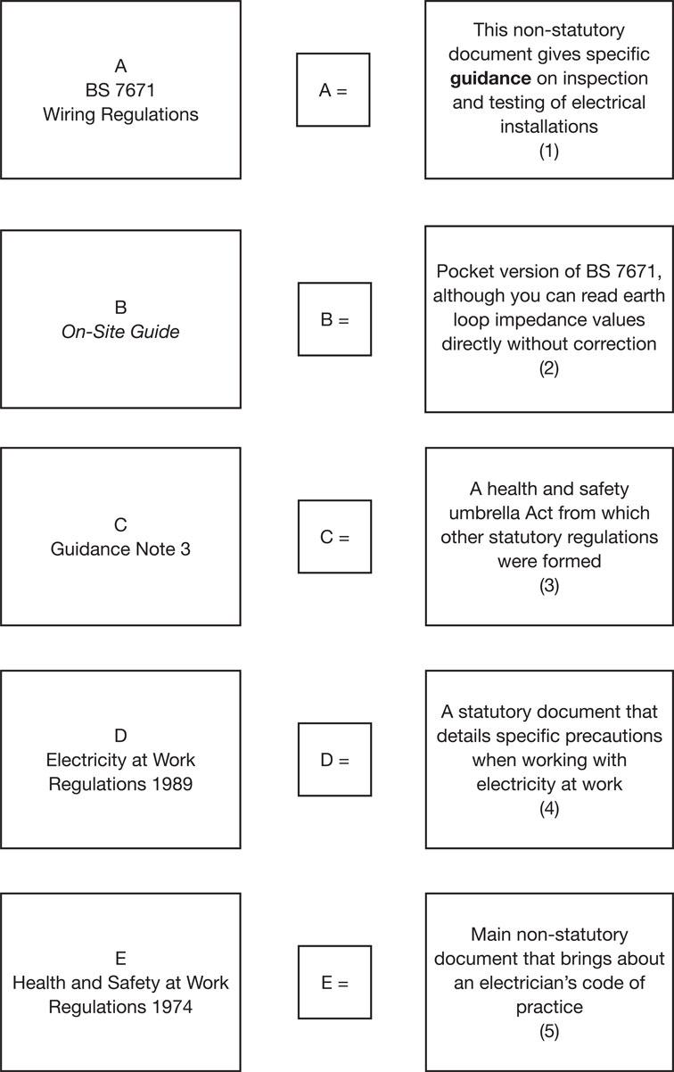
ELEC3/04A Electrical Installation Planning, Preparing and Designing
Chapter checklist
Learning outcome |
Assessment criteria |
Page number |
|---|---|---|
1. Understand how to plan for the installation of wiring systems and equipment. |
1.1 Interpret statutory and non-statutory requirements for the planned installation. |
112 |
1.2 Specify the criteria that affect the selection of wiring systems and equipment. |
122 |
|
1.3 Select wiring systems and equipment appropriate to the situation and use. |
126 |
|
1.4 Interpret sources of information relevant to planning of the installation of wiring systems and equipment. |
148 |
|
1.5 Plan wiring system routes. |
148 |
|
1.6 Specify the positional requirements of wiring systems and equipment. |
148 |
|
1.7 Interpret the requirements of BS 7671 for the planned installation. |
153 |
|
2. Understand protection against overcurrent. |
2.1 Specify the operating principles of overcurrent protection devices. |
199 |
2.2 Distinguish the application of overcurrent protection devices. |
205 |
|
2.3 Specify the advantages and limitations of different types of overcurrent protection devices. |
201 |
|
3. Understand earthing and protection. |
3.1 Distinguish earthing systems. |
207 |
3.2 Interpret the requirements for protection against electric shock. |
207 |
|
3.3 Select suitably sized protective conductors in accordance with BS 7671. |
216 |
|
4. Understand the electrical design procedure. |
4.1 Determine the design current. |
219 |
4.2 Select a suitably rated protective device. |
219 |
|
4.3 Establish the installation method reference. |
224 |
|
4.4 Apply appropriate rating factors. |
224 |
|
4.5 Determine the minimum current carrying capacity of live conductors. |
224 |
|
4.6 Establish if the voltage drop is acceptable. |
224 |
|
4.7 Verify if the disconnection times have been achieved. |
230 |
|
4.8 Evaluate thermal constraints. |
232 |
|
4.9 Establish the maximum disconnection times for different circuits. |
230 |
|
4.10 Verify discrimination between protective devices. |
206 |
|
4.11 Verify the fault current capacities of protective devices. |
199 |
|
5. Understand how to prepare the worksite. |
5.1 Specify the health and safety requirements in establishing a safe working environment. |
239 |
5.2 Specify how to ensure that worksites are correctly prepared. |
241 |
|
5.3 Clarify the preparations that should be completed before electrical installation work starts. |
242 |
|
5.4 Outline how to check for any pre-existing damage to customer/client property. |
242 |
|
5.5 State the actions that should be taken if preexisting damage to customer/client property is identified. |
242 |
|
5.6 Specify methods for protecting the fabric and structure of the property before and during installation work. |
242 |