In this chapter we return to a theme that we explored at some length in Chapter 4, the provision of wireless service to the largest possible number of users. In that chapter we focused on geographic coverage and introduced the frequency reuse technique to show how coverage can be provided to a practically unlimited number of users spread over a practically unlimited geographic area. In the present chapter we take a somewhat narrower perspective. We explore techniques for accommodating a maximum number of users in a fixed geographic area such as a cellular cluster, given a limited spectral allocation.
As we observed in the earlier chapter, radio spectrum is a limited resource, with certain specific bands allocated to cellular telephone and other bands to other wireless services. In our discussions we assumed that the system bandwidth Bsys allocated to a specific cellular system was subdivided into Nchan channels, each of bandwidth Bchan. The bandwidth Bchan was selected to provide one subscriber with a link having enough bandwidth to support an adequate quality of service for the subscriber's intended application. Thus, in one cellular cluster, using all of the channels, Nchan subscribers can enjoy simultaneous access. This technique of dividing the system bandwidth into channels by frequency is known as frequency-division multiple access. As we shall see in this chapter, a systems engineer has alternatives in the way that multiple users can be provided simultaneous service. The two additional techniques that we shall explore are known as time-division multiple access and code-division multiple access.
As an alternative to the frequency-division technique, time-division multiple access (TDMA) allocates the entire bandwidth Bsys to a single user, but only for a limited time. The various users take turns transmitting, usually in a round-robin fashion. Because individual users can transmit only momentarily, although at regular intervals, the signals from each user are effectively sampled during transmission. Time-division multiple access is most easily used with digital signaling schemes, since digital signals are already pulse based and hence single transmissions are limited in time. It is necessary to ensure that the round-robin proceeds fast enough that the successive pulses from each user can be transmitted as they become available.
All multiple-access schemes depend critically on the receiver's ability to separate the signals from various users. The receiver in a frequency-division system uses a filter to pass the desired signal and reject signals from other subscribers. The receiver in a time-division system uses time gating for that purpose; the receiver listens to the communication channel only during the appropriate time slots. It turns out that frequency selection and time gating are special cases of a more general technique. If signals from distinct users are transmitted using signal sets that are orthogonal, in the sense defined in Chapter 5, then these signal sets can be separated at the receiver by correlation. The use of specially designed orthogonal signal sets to support multiple users is called code-division multiple access (CDMA). Some of the orthogonal signal sets that have proved successful are derived from the same pseudorandom signals introduced in the previous chapter in connection with spread-spectrum signaling. We will examine code-division techniques in some detail later in this chapter.
When introducing techniques for sharing spectral resources among multiple users, it is helpful to distinguish between multiplexing and multiple-access techniques. These two terms refer to similar concepts and denote primarily a difference in emphasis. When the set of users is fixed in advance, or remains stable for long periods of time, the schemes for providing service are usually referred to as multiplexing. When users come and go at random moments, the term multiple-access is used. When describing multiple-access systems there is generally a greater emphasis placed on the techniques used by subscribers to gain access to a communication channel or a time slot. As an example, the architecture of the wired telephone network is based on multiplexing. Channels or time slots are assigned when a call is set up, and the assignments remain in effect until the call is released. The duration of a call is long enough that channel or slot assignments appear stable. A parallel situation exists in wireless telephone systems, where voice channels are assigned for the duration of a call, or at least until a mobile subscriber moves into an adjacent cell. An example of the multiple-access situation can be found in both wired and wireless data networks such as Ethernets or WiFi networks. These are packet networks in which subscribers transmit packets of several dozen to several thousand bytes of data at irregular intervals. Because each user's transmissions are irregular and infrequent, there is no point in assigning users to time slots. Users contend for access to the channel every time they wish to transmit a packet; the "winner" gets to transmit right away and the "losers" transmit later. As we will describe later in this chapter, this same contention-based time-division multiple-access situation appears in wireless telephone systems in the context of enabling users to access a control channel when initiating or answering a call.
From the point of view of a systems engineer, the choice of a multiple-access or multiplexing scheme is, like all other system design issues, governed by a desire to provide high-quality service to a maximum number of subscribers at a cost that will provide an appropriate return on investment to the service provider. Now, at the highest level of abstraction, the multiplexing scheme does not matter. A communication channel with a given bandwidth operating at a given signal-to-noise ratio can carry a given amount of information. In principle, the same number of users can be served whether the channel is divided in frequency, in time, or by code. In practice, however, the costs of the various multiplexing alternatives are very technology dependent. Thus, given a particular state of technology, one or another of the multiplexing schemes may be most cost-effective. As an example, we have mentioned that time-division multiple access is most effectively used with digital signaling. The cost of a given multiplexing scheme depends on available filter technology, on the modulation method used by the signals to be multiplexed, and on the processing power available at the transmitting and receiving points. A brief historical summary describing multiple-access methods in cellular systems will illustrate the point.
The original AMPS cellular system, introduced in the United States in the early 1980s, used frequency-division multiple access. The available spectrum was divided into 30 kHz channels as described in Chapter 4. The AMPS system used analog frequency modulation, in which the transmitted signals were continuous and not sampled. Consequently, frequency-division multiple access was virtually the only cost-effective choice for serving multiple simultaneous users. The 30 kHz channel bandwidth was a legacy from earlier mobile telephone systems and was originally dictated by the technology used to implement the receiver filters.
By the early 1990s AMPS systems were reaching capacity in some major cities, and it was desirable to find a way to support an increased number of simultaneous users in the available system bandwidth. Speech compression techniques had evolved to allow almost-telephone-quality voice signals to be transmitted at bit rates below 10 kbits/s, as compared with the wired telephone standard rate of 64 kbits/s, and it became possible to consider digital modulation methods to replace the analog FM. The U.S. Digital Cellular (USDC) system, introduced in 1991, used π/4-DQPSK (differential quadrature phase-shift keying) modulation in the existing 30 kHz channels. Pulse streams from three subscribers were time-division multiplexed in each channel, allowing an immediate increase in capacity. By keeping the existing channels, the operating companies were able to minimize their investment in new radio frequency hardware, making the migration to second-generation systems economically attractive. From a systems-engineering perspective it is important to note that advances in speech compression, modulation methods, and microprocessor technology during the 1980s made the use of time-division multiplexing feasible for cellular applications. The GSM system, the first digital cellular system introduced in Europe in the early 1990s, used GMSK modulation to time-division multiplex signals from eight subscribers onto one 200 kHz channel.
Also in the early 1990s Qualcomm, Inc., introduced a CDMA alternative to the USDC system. This system used QPSK modulation with direct-sequence spreading to support multiple users in 1.25 MHz channels. Although the capacity of the CDMA system is larger than that of USDC, the unfamiliar code-division technique along with the larger channel bandwidth initially led to a slow adoption of the system. The cdmaOne system (also known as IS-95) was successfully deployed in the mid-1990s and clearly demonstrated a significant improvement in spectral efficiency. As a result, CDMA techniques became universally adopted as the fundamental approach for third-generation (3G) cellular systems. The two major systems that are being deployed worldwide are cdma2000 and Wideband-CDMA (W-CDMA) (also known as the Universal Mobile Telecommunications System, UMTS). From a systems perspective, it is the increase in signal-processing capability of the mobile unit that has been the enabling technology in these third-generation systems.
This chapter begins with a high-level description of how cellular subscribers get access to a channel when a call is placed or received. This description is intended to provide an overview, in very general terms, of how multiple access actually works. Next we proceed to specifics of frequency-division, time-division, and code-division schemes. As frequency-division and time-division systems are conceptually straightforward, we will present one or two examples of classical systems to illustrate the concepts. Both frequency-division and time-division systems have firm upper limits on the number of users that can be accommodated in a given system bandwidth. We will examine some practical considerations that may cause the maximum number of users to be smaller than the upper limit.
A significant part of this chapter is an introduction to code-division multiple-access techniques. We begin by describing a CDMA system using frequency hopping and then turn to direct-sequence methods of providing CDMA. In each case we estimate the number of users that the system can service. We show that there is not a firm upper limit to the number of users. Instead, the signal-to-interference ratio for all users degrades gradually as the number of users increases. The practical limit to the number of users is governed by how much the service quality is allowed to degrade. We consider two specific examples of direct-sequence CDMA. First we explore the possibility of using orthogonal waveforms to separate the channels. This provides essentially perfect separation, at the cost of demanding requirements for synchronization. Next we examine the use of pseudonoise spreading codes to separate the channels. In this case the channel separation is not perfect, and each additional signal adds to the interference experienced by all of the users. On the other hand, the synchronization requirements are relaxed. It turns out that both of these CDMA methods are used in the cdmaOne and cdma2000 cellular systems. Orthogonal waveforms are used in the forward links and pseudonoise spreading codes in the reverse links.
In the final section of the chapter we examine contention-based access methods. We introduce the Aloha and slotted Aloha access techniques. The latter is widely used for mediating access to the control channels in cellular telephone systems. We conclude with an introduction to carrier-sense multiple access, a technique widely used in wireless data networks. For each of the contention-based techniques we carry out a performance analysis, so that the relative merits of the alternatives can be quantified.
Regardless of whether channels are provided by frequency division, time division, or code division, a cellular user wishing to place or receive a telephone call must obtain access to a voice channel pair. In this section we describe how that access is accomplished in very general terms. In our description we omit many details that are particular to one specific system or another and focus on the general multiple-access procedure. It is important to note that establishing access to a cellular system voice channel is essentially a circuit-switching operation. That means that once a channel, time slot, or code is assigned to a subscriber, the subscriber has exclusive use of that channel, time slot, or code, and the assignment remains in effect for the duration of the call. It is interesting to contrast the circuit-switching model with the packet-switching or contention-based access model that we will present later in this chapter.
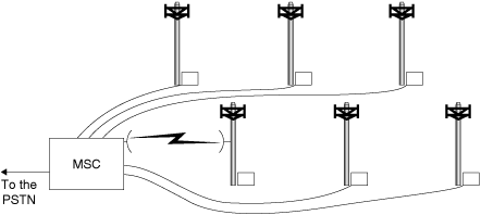
A simplified diagram showing the configuration of a cellular system was presented in Figure 4.20 of Chapter 4, repeated here as Figure 6.1. This diagram shows a set of base stations connected to a mobile switching center (MSC). The mobile switching center manages all of the channel assignments in the cellular system and also manages connections with the public switched telephone network (PSTN). Within a cellular system there is a large set of voice channels (dozens per cell) and a small set of control channels (a few per cell). (To make the discussion more readable, the term channel refers here to a frequency assignment, a time slot, or a code, as appropriate for the particular system.) There may in fact be several kinds of control channels. Some of these provide beacons containing synchronization information and system-dependent information needed by the mobile units. These are often called "sync" channels. Others, called "paging" channels, are used to alert a mobile unit to the arrival of an incoming call. Yet others are the "access" channels, which are reverse control channels used to implement the multiple-access procedure that we are about to describe. In this discussion we will not attempt to distinguish the various types of forward control channels in any precise way but will refer to them in the aggregate as "control channels." Access channels are a universally adopted reverse control channel type.
Figure 6.1. Base Stations Connected to a Mobile Switching Center
When a mobile phone is turned on, it scans a preprogrammed set of forward control channels looking for the strongest signal. The mobile unit tunes to the strongest control signal and obtains information that it needs to operate on the local system. This information may include access codes, location of the paging channels, and identification of the service provider. After it obtains sufficient information about the system, the mobile unit will register with the system using an access channel. If the mobile unit is not in its home system—that is, it is roaming—the service provider will verify the unit's right to service based on a suitable mutual service agreement with the unit's home system and will notify the home service provider about how to reroute calls. The mobile switching center also uses the forward control channel to periodically request mobile units to register with the service provider. Mobile units always respond to registration or paging alerts via an access channel.
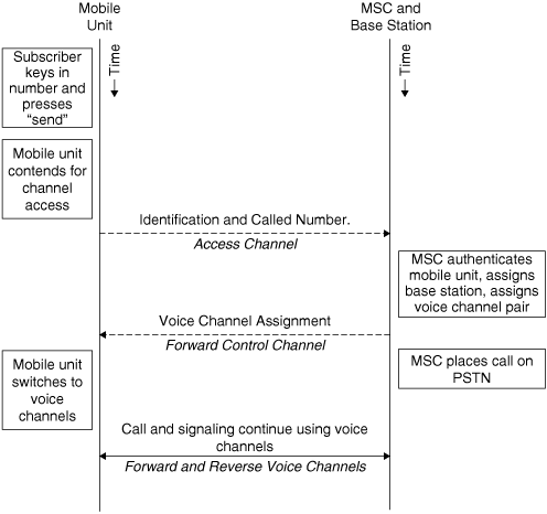
Once a mobile unit is powered up, tuned to a control channel, and known to the mobile switching center, it can initiate and respond to calls. The procedure for initiating a call is as follows.
This procedure is depicted graphically in Figure 6.2.
Figure 6.2. Procedure for Mobile Unit to Initiate a Call
The procedure for responding to an incoming call is similar.
This procedure is depicted graphically in Figure 6.3.
Figure 6.3. Procedure for Mobile Unit to Respond to a Call

The common theme that applies both to placing and to receiving calls is this: Mobile units must contend with each other to use an access channel, thereby allowing communication with the system. For most system implementations, access channels are used only when a voice channel has not been assigned to the mobile unit. Access channels are shared among multiple users, each of whose contribution to the overall control channel throughput is small. We will discuss contention-based access later in this chapter. Access to voice channels is not based on contention. Instead, voice channels are assigned to subscribers by the mobile switching center. Forward control channels are also controlled by the system, which can apportion messages to each user as necessary and to all users simultaneously when common messages are "broadcast" to all units. Therefore, even though all mobile units share the forward channels, there is no contention. When a mobile unit is operating on a traffic (voice) channel, all signaling messages with the system are carried by the traffic channel.
Frequency-division multiple access is the oldest of the multiple-access methods and was virtually the only option for circuit-switched or long-term users in the days before digital modulation became practical. From a system design perspective, the central issue is maximizing the number of independent users that can be simultaneously supported in a given system bandwidth. In this section we will identify the factors that limit the number of users and give several examples of frequency-division systems to illustrate the ideas.
As we observed in the introduction to this chapter, a simple calculation suggests that a system bandwidth Bsys divided among users each of whom requires a bandwidth Bchan can support Nchan = Bsys/Bchan simultaneous users. The challenge is determining an appropriate value to use for the parameter Bchan. At a minimum, the channel bandwidth Bchan must be wide enough to pass a modulated signal without unreasonable distortion. It is also the case, though, that the bandwidth Bchan determines how close in frequency adjacent signals can be placed. The channels must be separated by enough bandwidth to protect against adjacent-channel interference. Controlling this kind of interference can be the most important factor in determining a value for the channel spacing.
In Chapter 4 we provided an example in which we supposed that a base station received two signals from mobile transmitters using adjacent channels 30 kHz apart. We showed that under plausible assumptions about filter properties and propagation conditions a nearby interfering transmitter could provide a signal 50 dB stronger than the signal from a more distant cochannel transmitter. In the example this 50 dB difference was enough to overcome the stopband attenuation of the channel-selection filter. This example illustrates that to avoid such adjacent-channel interference it may be necessary to establish guard bands between channels. These guard bands constitute a kind of "overhead" and reduce the number of usable channels in the system bandwidth Bsys. As the example from Chapter 4 shows, the width needed for guard bands depends largely on two factors: the selectivity of the filters that can be used at the receivers to separate desired from undesired signals, and the range of relative amplitudes of the desired and interfering signals. The out-of-band spectral occupancy of the transmitted signal may also be a factor.
In the remainder of this section we provide several examples in which a bandwidth Bsys is subdivided to allow simultaneous transmission by a number of independent users. The first example is AM broadcast radio, the second is the frequency-division multiplexing scheme adopted by the North American telephone network prior to the introduction of digital transmission, and the third is the AMPS cellular telephone system. You will observe that these are all examples of legacy systems. Frequency-division multiplexing has been in use for a very long time, and the principles are the same whether one looks at historical or at modern communication systems. After we explore these classical frequency-division systems, we present an example that illustrates the consequences of poor spectral design of the transmitted signal. The section concludes with a discussion of frequency-division duplexing, a technique for providing two-way radio conversation.
A broadcast AM signal has a baseband (message) bandwidth of about 5 kHz. Since AM is a double-sideband modulation method, the transmitted signal bandwidth is 10 kHz. The AM broadcast band extends from 530 kHz to 1700 kHz. It is divided into channels, with carrier frequencies allowed every 10 kHz across the band. A naive calculation of Bsys/Bchan would suggest that 118 independent stations can be supported on this band in a given geographic location.
AM radios are mass produced and are generally optimized to minimize manufacturing costs. Consequently the filters that are typically used are not highly selective, certainly not selective enough to reject a strong station in an adjacent channel. As a result it is normal practice not to assign adjacent channels to stations operating in the same geographic area. As an illustration of actual practice, a quick look at the FCC Web site[1] shows that New York City has 16 active AM broadcast stations. These stations operate at carrier frequencies spread over the entire band, and in no case are stations assigned to carrier frequencies closer than 40 kHz apart.
Although there are no specific guard bands, it appears that assignment of stations on the AM band is made with Bchan ≥ 40 kHz. Using this wider channel bandwidth, we can determine that a fully populated AM band can support at most about 30 stations.
There is another consideration that further reduces the number of stations that can operate together on the AM broadcast band. A "Class A" AM station is authorized to transmit at a power level of up to 50,000 W. This is adequate to ensure good reception by receivers of possibly limited quality under poor propagation conditions over a large metropolitan area. It turns out, however, that when propagation conditions are good, such as on cold, clear winter nights when atmospheric noise is at a minimum, these powerful AM signals can be received over distances of a thousand miles or more. To avoid cochannel interference between these stations, a number of AM channels are designated as "clear" channels. Clear channels can be assigned to more than one station, but stations assigned to the same clear channel are located at least half a continent apart. (If this were a cellular system, think of the cell size!) As an example, station WBZ transmits from Boston, Massachusetts, on 1030 kHz. The same frequency is used by KTWO in Casper, Wyoming, but the clear-channel frequency of 1030 kHz is not available for assignment at other locations on the East Coast.
This example clearly shows how considerations of adjacent-channel and cochannel interference reduce the number of stations that a frequency-division multiple-access system can support in a given system bandwidth. Stations could be spaced more closely together if filters having greater selectivity were used in the receivers. This is not a cost-effective option for AM broadcasting, but our next example will show a different application in which selective filters were effectively used.
Perhaps the classic example of efficient frequency-division multiplexing is the system used by the telephone companies for long-distance telephone transmission. This system became highly developed during the 1950s and persisted into the 1970s, when it began to be gradually replaced by time-division multiplexing.
The baseband input to the telephone multiplexing hierarchy was (and still is) the voice signal. Voice signals are filtered as they enter the switching office, using a filter with a 4 kHz stopband bandwidth. The passband bandwidth is somewhat narrower, in the range of about 3200 to 3600 Hz. To form the multiplexed signal, 12 voice signals were modulated onto distinct carriers using single-sideband modulation. Given the strict 4 kHz message bandwidth, the bandwidth of a modulated signal is also 4 kHz. It was then possible to space the carrier frequencies 4 kHz apart so that the combined signal, known as a "group," occupied a total bandwidth of 48 kHz. As all 12 signals were transmitted from the same location and received at the same location, signal levels could be balanced, so that there was no problem with interference to a weak in-channel signal from a strong adjacent-channel signal. The filters used to generate the single-sideband modulated signals and also to separate signals at the receiver were specialized sharp-cutoff filters constructed from mechanical resonators. Hence adjacent 4 kHz channels could be used, without allocating guard bands or leaving empty channels between each pair of occupied channels.
Once 12 voice channels were combined into a group, the group could be treated as a "message" signal with a 48 kHz bandwidth. Five groups could then be combined into a "supergroup," also by using single-sideband modulation. As in forming a group, adjacent channels were spaced at the minimum spacing, in this case 48 kHz, with all channels used. The supergroup bandwidth was 240 kHz. Subsequently ten supergroups were combined into a "mastergroup," and six mastergroups were combined into a "jumbo group." A jumbo group contained 3600 voice signals. The jumbo group signal could be transmitted over coaxial cable or used as the baseband input into a microwave transmitter.
The AMPS cellular telephone system was introduced in Chapter 4. The AMPS system uses 30 kHz channels, with 395 voice channels available to be assigned to each of "A side" and "B side" operating companies. Table 4.3 shows part of a channel plan assuming seven-cell clusters, with each cell divided into three 120° sectors. As was pointed out in Chapter 4, the channel plan ensures that channels assigned to the same cell are spaced at least 15 channels apart, and channels assigned to the same sector are spaced by at least 21 channels. Thus we see that although there are no guard bands between channels, and all channels are used, significant spacing is guaranteed between channels that will be used in the same geographic area. It is important to note that the same minimum channel spacing could not be guaranteed if a smaller cluster size were used, as more channels would then be assigned to each cell.
As we observed previously, the second-generation U.S. Digital Cellular system uses the same 30 kHz channels used in the AMPS system. The cdmaOne system, however, uses 1.25 MHz channels. It is possible for cdmaOne and AMPS systems to coexist in the same geographic area if 1.25 MHz of the cellular band is allocated to the cdmaOne system. In this case, though, a guard band of nine AMPS channels must be set aside on each side of the cdmaOne subband to avoid interference between the systems.
The efficiency of a frequency-division multiple-access system can be adversely affected by poor spectral shaping of the transmitted signal. The following example illustrates what can happen.
Example
In a certain frequency-division multiple-access system the transmitters transmit data using binary phase-shift keying with a bit rate of 10 kbits/s. Rectangular pulses are used with no filtering at the transmitter. Channels are spaced every 20 kHz. Suppose the receivers use highly selective filters that we can take as ideal brick-wall (i.e., "rectangular" frequency response) filters, each having a bandwidth of 20 kHz centered on the appropriate carrier frequency.
Suppose a receiver receives two signals of equal amplitude. One of these is the desired signal, and the other has a carrier frequency n channels away from the carrier frequency of the desired signal.
How large must we make n so that the signal-to-interference ratio is at least 40 dB?
Solution
A binary phase-shift keyed signal can be written
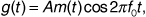
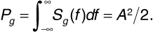
where A is the amplitude, m (t) is the message consisting of a train of polar NRZ rectangular pulses, and f0 is the carrier frequency of channel "zero." The power spectrum of this signal is given by

The power in this signal is the area under the power spectrum, that is,
The received signal power is the power in the passband of the receiver filter. The receiver filter passband occupies one channel and extends from f0 - 104 to f0 + 104, giving
that is,
We see that the receiver filter passes more than 90% of the power available. If the interfering signal has a carrier frequency of fn = f0 + 2 x 10⁴ n, then the power received from the interfering signal is
The signal-to-interference ratio is given by
Numerical evaluation of the integral in Equation (6.6) and substitution in Equation (6.7) shows that the signal-to-interference ratio reaches 40 dB when n = 17.
This example shows that even with perfect brick-wall receiver filters, geographically colocated transmitters must use a channel spacing of at least 17 when the transmitted signals have a spectrum that falls off as slowly with frequency as does the spectrum of a rectangular pulse. The efficiency of the multiple-access system can be improved significantly if the pulses are shaped, for example, with a raised-cosine spectrum.
A radio cannot transmit and receive simultaneously on the same frequency, unless separate and widely spaced transmitting and receiving antennas are used. The transmitted power level is so much higher than the power levels that the receiver is designed to expect that any leakage of power from the transmitter directly into the receiver can desensitize the receiver or possibly even damage components in the receiver front end. Mobile radios such as cellular telephones use a single antenna for both transmitting and receiving, and even cellular base stations locate their transmitting and receiving antennas on a common tower.
The traditional method of separating transmission and reception in a mobile unit is to operate half duplex. This means that the user alternately transmits and listens, as on a walkie-talkie. Now half-duplex operation is effective for data transmission, but most subscribers find the mode awkward for conversation. Land telephones provide full-duplex service, in which the subscriber can talk and listen at the same time (at least the telephone can do this). To provide full-duplex service using a mobile radio, either it is necessary to interleave the transmitting and receiving functions in time in a way that is transparent to the user, or it is necessary to transmit and receive on different frequencies.
Frequency-division duplexing provides two separate bands of frequencies for each user. A forward channel in one of the bands carries information from the base station to the mobile unit, and a reverse channel in the other band carries information from the mobile unit to the base station. The two channels together are sometimes referred to as a single full-duplex channel. A bandpass filter called a "duplexer" is used in each mobile unit and in the base station to prevent energy from the transmitter from reaching the receiver input. The forward and reverse channels must be separated in frequency by enough bandwidth to allow the duplexer to attenuate the transmitted signals in the receive band, but not so far in frequency that a common antenna cannot be used for transmitting and receiving. In multichannel systems the separation in frequency between the forward channel and the reverse channel is often a fixed constant to simplify the design of the duplexer. Forward and reverse channels are assigned in pairs that preserve the fixed frequency spacing.
In the AMPS cellular telephone system frequency-division duplexing was used with a spacing of 45 MHz between corresponding forward and reverse channels. Frequency-division duplexing with the 45 MHz spacing was preserved in the migration to U.S. Digital Cellular, cdmaOne, and also in the third-generation cdma2000. Frequency-division duplexing is also used in the GSM system.
Suppose, as above, that we have a multiple-access system with an allocated bandwidth of Bsys that is to support communications among users whose signals each have bandwidth Bchan. According to the sampling theorem, the signal produced by a user can be sampled without loss of information, provided that the sampling rate is greater than 2Bchan samples per second. Also according to the sampling theorem, a smooth waveform of bandwidth Bsys or less can be passed through a sequence of arbitrary samples, as long as the samples are provided at a rate less than 2Bsys samples per second. Now, if this sequence of arbitrary samples is generated by taking samples in round-robin fashion from a group of Nchan users, then the number of users is bounded by
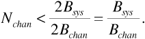
Thus, according to this simple argument, the maximum possible number of users that can be supported by a time-division multiple-access system is the same as the maximum number of users that can be supported by a frequency-division multiple-access system.
Where this argument runs into difficulty is that in digital transmission systems the samples of the transmitted signal are quantized, and each quantized sample is represented as a series of bits. If, in the round-robin, each user supplies a value that represents a bit rather than a value that represents a sample, the user may be supplying values at many times the 2Bchan rate. The number of such users that the system can support will be correspondingly reduced.
Example
We have seen that in wired telephone systems voice signals are filtered to a stopband bandwidth of 4 kHz when the signals enter the switching office. A 4 kHz signal can be sampled at 8000 samples per second. Now standard practice in the wired telephone industry is to represent each sample as an eight-bit number. Thus a single voice signal produces a 64,000 bit/s bit stream. If this bit stream were encoded using a polar-keyed line code, transmission would require 64,000 pulses/second. The pulses having minimum bandwidth are sinc-function shaped. Using sinc-function pulses, the bandwidth of the line code would be 32 kHz. Of course, sinc-function pulses are not necessarily practical, as they are very susceptible to errors caused by timing jitter at the receiver. Using raised-cosine-shaped pulses would produce a more robust system but would increase the bandwidth to a value between 32 and 64 kHz.
This example suggests that the use of time-division multiple access with digital transmission can reduce the number of users by a factor of between 8 and 16 compared with frequency-division multiple access. There are two ways by which the efficiency of the time-division scheme might be improved. First, if a multilevel line code were used, each user would be able to transmit fewer pulses per second. There is a trade-off, however, since for a given signal-to-noise ratio, a multilevel line code experiences a higher bit error rate than does a binary line code. Second, a more efficient way of digitizing the source data might be found. In cellular telephone systems, the introduction of time-division multiple access depended critically on the availability of speech processors that could sample and quantize "telephone-quality" voice signals at much lower bit rates than the 64,000 bits/s used in wired telephone. The use of sophisticated speech processing in cellular systems is a consequence both of improvements in the processing algorithms and also of improvements in digital signal processor technology that allow powerful processors to be included in small mobile handsets.
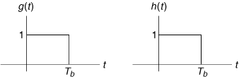
In a time-division multiple-access system signals from multiple users are sampled in rotation. The composite signal containing one contribution from each user is called a frame. A typical frame structure is shown in Figure 6.4.
Figure 6.4. A TDMA Frame
(Adapted from Figure 9.4 of T. S. Rappaport, Wireless Communications, 2nd ed. (Upper Saddle River, NJ: Prentice Hall, 2002).
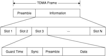
Frames are repeated cyclically. Each user is assigned to an individual slot, and the user transmits at regular intervals when that slot is available. It is apparent in the figure that more information is contained in the frame than just the data from each user. The frame preamble is needed so that the receiver can identify the start of the frame. Correct identification of the start of the frame is needed so that the receiver can correctly distribute data to the various users. In the figure each slot is shown as containing a preamble as well. These preambles allow the receiver to locate the start of data within each slot. Also, in a multiple-access system the user assigned to a given slot may change when, for example, a call terminates. The preamble may contain addressing information that identifies the user transmitting in the slot. In a wireless system individual users must key their transmitters when the slot time to which they have been assigned begins. The "guard time" allows time for radios to switch from receive to transmit or transmit to receive and for the transmitting radio to power up. The "sync" interval allows the radio starting a transmission to transmit a periodic signal so that the receiver can synchronize to the carrier and bit clock.
All of the guard, sync, and preamble intervals constitute overhead in the time-division multiple-access system. The presence of this overhead reduces the time that can be allocated to user data and thus reduces the number of users that can be supported in a given system bandwidth. The need for guard and sync intervals is a consequence of the application of time-division multiple access to a wireless system with multiple transmitters. These intervals would not be needed for a wire-based system with a single transmitter and receiver. The length of the preamble is determined to some extent by the signal-to-noise ratio and by the consequences of incorrect frame reception. In the DS-1 (digital signaling, level 1) time-division multiplexing system introduced for wired telephone systems in the 1960s, there were no guard or sync intervals at all, and the "preamble" was reduced to a single bit per frame!
In the remainder of this section we provide two examples of practical time-division multiple-access systems. We show the frame and slot structure for the U.S. Digital Cellular and GSM systems. These examples provide a look at some practical transmission rates and illustrate the number of users that can be supported by these systems in a given channel bandwidth. The examples also show clearly how much and what kind of overhead practical time-division systems require. Following the examples, we introduce the concept of time-division duplexing. This discussion complements the discussion of frequency-division duplexing in the previous section and shows, again by example, an alternative means of avoiding the necessity of transmitting and receiving on the same frequency at the same time.
The U.S. Digital Cellular (USDC) system is a second-generation cellular telephone system that was introduced in the early 1990s to offer an increase in capacity over that achievable with AMPS. The USDC system was designed to coexist with AMPS systems to make upgrading to the new system as easy as possible for operating companies. The USDC system uses the same 30 kHz channels that were allocated for AMPS, but transmission is digital. The modulation method is π/4-DQPSK at a pulse rate of 24,300 pulses/second. To restrict the signals to the allocated bandwidth, square-root raised-cosine pulse shaping is used, with a rolloff factor of 0.35. Quadrature modulation at 24,300 pulses/second gives a bit rate of 48.6 kbits/s. The transmitted signal is divided into frames of 40 ms duration, with each frame containing 1944 bits. Each frame is divided into six slots of 324 bits each. The USDC system can carry six "half-rate" or three "full-rate" voice signals per 30 kHz channel. For full-rate service, the first user occupies slots 1 and 4, the second user slots 2 and 5, and the third user slots 3 and 6.
For a cellular system to operate properly, a certain amount of "signaling" or supervisory information must be sent along with the voice signals. The 48.6 kbit/s bit stream in one 30 kHz channel actually carries four "logical" channels for each user. The first of these is the "digital traffic channel" (DTC) that carries the digitized voice signals or other user data. Next there is a "coded digital verification color code" (CDVCC), a "slow associated control channel" (SACCH), and finally a "fast associated control channel" (FACCH). The CDVCC is a 12-bit coded message sent in every time slot. The message is originated at the base station and echoed back by the mobile unit. The CDVCC helps to ensure that the mobile unit is receiving signals from the correct base station. If the correct CDVCC is not echoed back, the mobile unit transmitter is turned off and the time slot reassigned. The SACCH is also implemented as a 12-bit message sent in every time slot. This channel is used to communicate power level changes to the mobile unit and to allow the mobile unit to report the signal strength of nearby base stations. The FACCH, when it is needed, uses the field in each slot normally allocated to user data. The FACCH is used to transmit dual-tone multifrequency (DTMF) dialing information, call release instructions, and handoff requests.
Figure 6.5 shows the structure of one slot in the forward and in the reverse link. In the forward link, 28 bits of synchronization are followed by the SACCH bits. The 260 bits of data are divided into two 130-bit segments with the CDVCC between them. There are 12 bits "left over" at the end of the slot. In the reverse link, 6 bits each are allocated for guard and ramp-up of the mobile transmitter. The 260 bits of data are divided into three segments and interleaved with the synchronization bits, the SACCH bits, and the CDVCC as shown. Note that the FACCH is not shown. When needed, the FACCH uses the bits otherwise assigned to data.
Figure 6.5. Structure of a USDC Time Slot
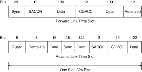
It is interesting to note how much of each time slot is allocated to "overhead" in the form of supervisory channels, synchronization, guard, and ramp-up time. In fact there is even more overhead than first appears, since of the 260 bits allocated to data, 101 are used for error control.
One time slot of 324 bits actually has room for only 159 bits of digitized voice. Now at "full" rate, each user is given two time slots per frame. Twice 159 bits is 318 bits, and at 318 bits per 40 ms frame, the voice signal bit rate is 7.95 kbits/s.
From a systems perspective it is important to recognize where the increase in capacity that USDC offers over AMPS comes from. First, the π/4-DQPSK used by USDC is a linear modulation method, and linear modulation would allow more than one voice signal to be transmitted in a 30 kHz channel, even without digitization. The digital modulation restores the noise immunity provided by FM. Second, quadrature modulation allows the transmission of two bits per pulse. Third, and perhaps most significant, the speech processor encodes voice signals at 7.95 kbits/s, which is a significantly lower bit rate than the 64 kbits/s associated with speech transmission over wired telephone systems.
GSM is a second-generation cellular system introduced in Europe in 1991 but now used worldwide. GSM was designed to provide a common cellular system throughout Europe, to replace the incompatible national first-generation systems that then existed. GSM was originally assigned to the 900 MHz cellular band in Europe, but it is also used in the 1800 MHz PCS band in the United States and elsewhere. GSM transmits in 200 kHz channels using GMSK modulation at a bit rate of 270.833 kbits/s. Frames have a duration of 4.615 ms and carry 1250 bits.
GSM has a variety of frame structures, depending on whether the frames carry traffic or control signals. There are six formats for traffic channels; the format used depends on whether the channel carries full-rate speech, half-rate speech, or data at any of several bit rates. In this discussion we describe only the format used for full-rate speech, as this is adequate to illustrate the time-division multiple-access principle. There are a number of excellent references that can provide further information.[2]
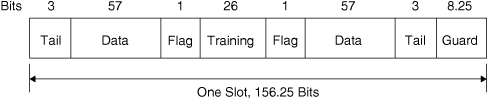
A GSM frame is divided into eight slots, each 576.92 μs or 156.25 bit times in duration. With eight slots, up to eight subscribers can share one 200 kHz frequency assignment. The "normal" format for a single time slot of full-rate speech is shown in Figure 6.6. In the format shown, the three tail bits at the start and end of the slot and the guard interval of 8.25 bit-times duration allow for transmit-receive switching, transmitter ramp-up, and synchronization. The slot carries 114 bits of data divided into two 57-bit segments. The 2 flag bits are used to indicate that subscriber data is present in the data segments. As was the case in the USDC system, the data fields can be used as a fast associated control channel (FACCH) when needed. A feature that we have not encountered in our examination of the USDC system is the 26-bit "training" field in the center of the slot. This field carries a known bit pattern that the receiver uses to assess the frequency response of the communication channel. The 200 kHz channel bandwidth is wide enough that frequency-selective fading can cause significant intersymbol interference. Using the bits in the "training" field, the receiver can adjust an equalizing filter to reduce the frequency-selective effects.
Figure 6.6. Structure of a GSM Slot, Format Used for Full-Rate Speech
Twenty-six GSM frames are grouped together into a "multiframe." In each multiframe, the thirteenth and twenty-sixth frames do not carry data. The thirteenth frame carries eight slots of slow associated control channel (SACCH) data, one control channel for each of the eight traffic channels carried in the remaining frames. The twenty-sixth frame is idle. (It is used for SACCH data in the "half-rate" speech format.) Given the slot, frame, and multiframe structure, we can calculate the overall rate at which user traffic is transmitted. One user is allocated one slot per frame. This slot carries 114 traffic bits in every frame time of 4.615 ms. Dividing gives a bit rate of 24.7 kbits/s. This bit rate must be reduced by a factor of 12/13, since only 24 of every 26 frames carry user traffic. The result is a user traffic rate of 22.8 kbits/s.
The subscriber traffic that fills the "data" fields of each slot is digitized speech. The speech coder processes speech in 20 ms blocks, producing 260 bits in each block. This gives a data rate of 13 kbits/s. Prior to transmission, each block of 260 bits has an additional 196 bits added for error correction. The resulting 456 bits per 20 ms gives the 22.8 kbit/s user traffic rate referred to in the preceding paragraph.
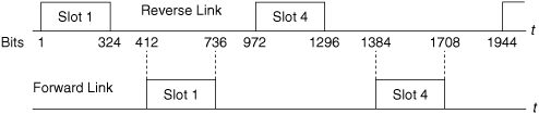
The USDC system is usually described as a frequency-division duplexed system, since the forward and reverse links use frequencies in separate bands. Since USDC operates using the AMPS channels, the forward and reverse transmissions are always assigned frequencies separated by 45 MHz. In the USDC system, however, there is a second duplexing method that takes advantage of the fact that each transmission is a burst of 324 bits followed by a period of silence during which other users transmit. In this system the forward and reverse channels are synchronized so that transmission of slot 1 in the forward direction begins 412 bit times later than transmission of slot 1 of the corresponding frame in the reverse direction. The timing is shown in Figure 6.7. It is apparent from the figure that a station never actually transmits and receives at the same time. It should also be clear that the same relative timing would apply for a station using slots 2 and 5, or 3 and 6. A radio that does not transmit and receive at the same time does not need a duplexer. The staggered time relation allows the cost of the radio to be reduced.
Figure 6.7. Timing of Reverse and Forward Links in USDC
Generalizing the preceding discussion, we see that a radio that transmits and receives during nonoverlapping slots does not actually need to use separate frequencies for the forward and reverse links. A scheme in which duplexing is achieved by separate transmit and receive time intervals rather than separate frequencies is called time-division duplexing. Time-division duplexing differs from half-duplex operation. In the former case the transmission slots are short and spaced closely enough together that the user perceives communications in both directions as simultaneous. In the latter case the user is aware of separate time intervals allocated for talking and listening.
Time-division duplexing is used in a number of cordless phone systems. It tends to work best over short transmission distances, as significant propagation delay can interfere with the slot coordination. Even more damaging is the time-varying propagation delay that can result when one or both of the radios is moving rapidly.
Code-division multiple-access techniques are based on spread-spectrum modulation. Spread-spectrum modulation was introduced at the end of Chapter 5, where we showed two such techniques: frequency-hopping spread spectrum and direct-sequence spread spectrum. Spread spectrum is defined by the use of a signal, unrelated to the information content of the transmitted message, to spread the bandwidth of the transmitted signal. We showed in Chapter 5 that spread-spectrum modulation offers advantages in providing resistance to narrowband interference as well as providing robustness in the presence of frequency-selective fading.
Because a spread-spectrum signal is created to have an artificially wide bandwidth, it might seem that this kind of signaling is unsuited for a densely channeled system such as a cellular telephone system designed to support a maximum number of subscribers. In fact, spread-spectrum systems have traditionally been used in situations in which the information data rate is very low, the channel bandwidth is relatively unrestricted, or the spreading is so broad that narrowband users have been able to coexist with the spread-spectrum system without being aware of its presence. We show in this section that multiple spread-spectrum transmitters can share a common communication channel if their spreading codes are distinct and properly chosen. This ability of spread-spectrum signals to be distinguished by their spreading code leads to the code-division multiple-access method that can be used as an alternative to frequency-division or time-division multiple access.
Both frequency-hopping and direct-sequence spread-spectrum systems can be used for code-division multiple-access communications. Bluetooth, for example, is a frequency-hopped system. Multiple Bluetooth "piconets" can exist with overlapping coverage areas if distinct spreading codes are used. Cellular telephone applications of code-division multiple access use direct-sequence spread spectrum. Direct-sequence systems include the second-generation cdmaOne as well as the third-generation cdma2000 and Wideband CDMA. We will describe both frequency-hopping and direct-sequence systems in this section. We begin with a somewhat brief description of frequency-hopping CDMA. Frequency hopping is easier to understand than direct sequence, and it provides an effective framework for introducing some of the important properties and limitations of the technique. We will then move to the direct-sequence case. Our purpose in the discussion is twofold: On the one hand we describe how CDMA systems work, and on the other we wish to determine the number of subscribers that a system can support, given system parameters such as system bandwidth and available signal-to-noise ratio. Our discussions will focus on "generic" CDMA systems. Space does not permit getting into the implementation details of commercial second- and third-generation cellular systems. For those details the reader is referred to the standards documents or to textbooks written at a more advanced level.
A frequency-hopping spread-spectrum system is shown in simplified block diagram form in Figure 6.8. Recall that the PN sequence generator controls the frequency synthesizer in such a way that the frequency of the transmitted carrier hops at regular intervals among a predetermined set of frequencies. The receiver is equipped with an identical PN sequence generator and frequency synthesizer. The receiver tracks the carrier of the transmitted signal so that the received signal can be continuously demodulated. The PN sequence is usually designed so that the transmitted carrier makes equal use of all of the available frequencies. To an outside observer the hopping pattern appears random, though of course it is not random, as the receiver knows the pattern.
Figure 6.8. Frequency-Hopped Spread-Spectrum System: (a) Transmitter; (b) Receiver
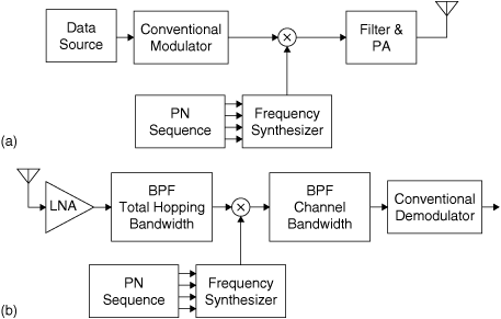
Figure 6.8 is simplified in that it does not show the circuits needed to synchronize the PN generators in the transmitter and the receiver.
Frequency hopping works well with any modulation method. It has been used with analog AM and FM, as well as with advanced digital modulation techniques. It is common practice to use FSK in frequency-hopping systems, as the constant envelope of the FSK signal is not impaired by the hopping.
Example
Suppose noncoherent FSK is used in a frequency-hopping spread-spectrum system. If the channel noise is white, and fading is not frequency selective, then the signal-to-noise ratio will be the same at each of the possible carrier frequencies in the hopping set. This means that the probability of error will not be affected by the fact that the carrier frequency changes at regular intervals. For noncoherent FSK we have
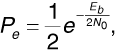
where Eb is the energy per bit, and N0/2 is the noise power spectral density.
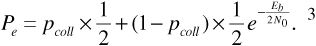
Now let us suppose that two frequency-hopping systems share the same set of carrier frequencies. If the two systems use different PN sequences to control their hopping, then each transmitter-receiver pair will perceive the other transmitter to be hopping at random. Every once in a while the two transmitters will hop onto the same carrier frequency. This is called a "collision" or a "hit," and when a collision occurs we can expect that the signals obtained by both receivers will be severely impaired. In fact, for modeling purposes, let us make the worst-case assumption that when a collision occurs, the probability of error becomes Pe = 0.5. If the probability of collision is pcoll2 then the average probability of error experienced by one of the receivers is
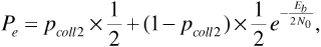
where we have continued to assume for purposes of illustration that noncoherent FSK is the modulation method used.
To complete our calculation of the probability of error for this two-transmitter-receiver-pair system, we need to obtain a value for pcoll2. Suppose there are q carrier frequencies in the hopping set. For the purposes of example, let us assume that a slow-hopping system is used, with Nb bits of data transmitted between hops. We will also make the reasonable assumption that the two transmitter-receiver pairs are not synchronized but hop independently of each other.
For purposes of discussion, let the two transmitter-receiver pairs be designated as "pair A" and "pair B." We calculate the performance of pair A in the presence of pair B. Let us now pick a particular moment in time when pair A is occupying a carrier frequency designated as f0. There are two ways that pair B can collide with pair A. One possibility is that at the start of the current bit time, pair B is also using carrier frequency f0. The other possibility is that at the start of the current bit time pair B is using some other carrier frequency but hops to frequency f0 during the current bit time. Now the probability that pair B is using frequency f0 at the start of the current bit time is 1/q. Consequently, the probability that pair B is not using frequency f0 must be 1 - 1/q.
Each transmitter-receiver pair hops once every Nb bit times. Since the two systems are not synchronized, the time at which pair B hops is uniformly distributed over the Nb bit-time interval. Therefore, the probability that pair B will hop during just one bit time is 1/Nb. Thus we see that the probability that pair B is not using frequency f0 at the start of the current bit time and hops during the current bit is  . Now when pair B hops, it may land on any of q - 1 destinations, assuming that it cannot hop back onto its original frequency. We see that the probability that pair B is not using frequency f0, but hops during the current bit time landing on f0 (thereby causing a collision), is
 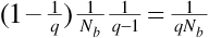 . Finally, we put the pieces together. The probability pcoll2 for a two-transmitter-receiver-pair system is
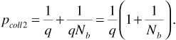
Having reached this point, we can easily generalize to the case in which there are more than two transmitter-receiver pairs. Suppose that there are K such pairs. To find pcoll for this larger system we reason as follows. We begin as before, by singling out one transmitter-receiver pair and calling the frequency on which it is transmitting f0. The probability that a second transmitter-receiver pair collides during the current bit interval is pcoll2, given by Equation (6.11). The probability that this second transmitter-receiver pair does not collide during the current bit interval is then 1 - pcoll2. The probability that none of the other K - 1 transmitter-receiver pairs collide during the current bit interval is (1 - pcoll2)(K-1). Therefore, the probability of one or more collisions during the current bit interval is
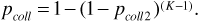
The probability of error for this K transmitter-receiver pair system is given by Equation (6.10), with pcoll substituted for pcoll2 that is,
Example
Consider a slow-hopping system with Nb = 625 bits/hop and q = 80 hopping frequencies. Figure 6.9 shows probability of error plotted against Eb/N0 from Equations (6.13), (6.12), and (6.11), assuming that there are K = 1,2,5, and 10 users.[3]
Figure 6.9. Probability of Error versus Eb/N0 for Frequency Hopping with Nb = 625 Bits/Hop, q = 80 Frequencies, and K = 1, 2, 5, and 10 Users
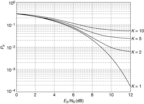
Several observations can be made from this simple example. First, when there is more than one user, the probability of error does not continue to decrease as Eb/N0 is increased. Instead, there is a so-called irreducible error rate that is reached when Eb/N0 becomes large enough. For large Eb/N0, virtually no bit errors are caused by the channel noise. Instead, nearly all errors are caused by collisions. In this case the probability of error can be reduced only by increasing the number of hopping frequencies or reducing the number of users.
A second observation is that for the numbers used in this example, the probability of error achieved is very high. In practice, CDMA systems used for voice transmission often use error-correcting codes to lower the probability of error. The errors caused by collisions tend to occur in bursts lasting from 1 to Nb bits. There are error-correcting codes that are very effective at correcting bursts of errors, provided the burst duration is not too long. To deal with long bursts, data is often "interleaved" before transmission. This means that blocks of data are shuffled, like a deck of cards, prior to transmission and unshuffled after reception. The interleaving (and de-interleaving) has no effect on the data, but bursts of errors become spread out by the de-interleaving, so that the error-correcting code can deal with the errors more effectively.
In our preceding discussions we assumed that the frequency-hopping system was a slow hopper. A similar analysis can be done for the fast-hopping case. When fast hopping is used there are several hops per bit time, which means that there are multiple opportunities per bit time for collisions. If the hopping is very fast, so that the hop time is much shorter than the bit time, a single collision may not cause enough disturbance to produce a bit error. Thus a fast-hopping system may in fact be more robust than a calculation based on a simple model might indicate.
For our final observation we return to the fundamental question: How many subscribers can a frequency-hopped multiple-access system support? It is apparent from Figure 6.9 that each user added to the system causes an increase in the probability of error for all users. Thus the number of users is not limited by a firm bound as is the case for frequency-division and time-division multiple-access systems. For a frequency-hopping system the number of users is limited by the quality of service that the system is designed to provide to each user. This "soft" limit in number of users provides an operational advantage, as there may be cases when it is desirable to add a user beyond the quality of service limit, if the user will be present for only a limited time. We will see in the next section that the soft limit on number of users applies to direct-sequence multiple-access systems as well.
A direct-sequence spread-spectrum system is shown in block diagram form in Figure 6.10. Direct-sequence spread spectrum was introduced in Chapter 5. We will review briefly how the system works and then proceed to the main issue before us: how multiple users can be supported on the same carrier frequency. We will show that multiple access can be very effective with this system, provided the spreading codes are chosen appropriately. Two cases will be investigated, both of practical importance in CDMA cellular telephone systems. First, we will investigate the case in which users are assigned orthogonal spreading codes. In this case the spreading codes may not be very effective at spreading the spectrum, and distinct users must be synchronized. In return, however, multiple users can be perfectly separated and do not cause interference to each other. Second, we will explore the case in which the spreading codes are pseudonoise sequences. In this case the signal bandwidth will be effectively spread, leading to the benefits discussed in Chapter 5 relating to narrowband interference resistance and robustness in the presence of frequency-selective fading. For this case, distinct users do not have to be synchronized. We will show, however, that multiple users are not perfectly separated and that the overall interference level increases with each user added.
Figure 6.10. Direct-Sequence Spread-Spectrum System: (a) Transmitter; (b) Receiver
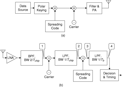
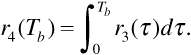
Referring to Figure 6.10, let us denote the signal at the receiver input by

where m (t) is the message, assumed to be a polar NRZ signal consisting of rectangular pulses of duration Tb; p (t) is the spreading code, also assumed to be a polar NRZ signal of rectangular pulses of duration Tchip; fc is the carrier frequency; and n (t) is additive white Gaussian noise, with power spectral density N0/2. Note that we are taking both the message and spreading code pulses as rectangular to simplify our discussion, even though in practice the pulses would be shaped to limit adjacent-channel interference. Further, we assume that both the message and the spreading code take values of ±1; we will use the parameter A to set the level of the received signal. For future reference the received signal power Ps is given by
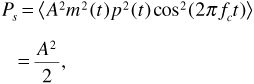
where we have used the facts that m2 (t) = p2 (t) = 1 and  . Finally, we recollect that in a direct-sequence spread-spectrum system, we always have Tchip
  Tb.
Tb.
The first stage of the receiver is conventional and consists of a low-noise amplifier and a bandpass filter. The filter bandwidth is approximately 2/Tchip, which is wide enough to pass the spread signal without significant distortion. In our discussion we will assume that all filters have rectangular passbands and unity gain, unless we specifically state otherwise. At point 1 in the system we have

Only the noise level is affected by the bandpass filter. The noise power spectrum is still Sn1 (f) = N0/2, but the noise is now bandlimited to a bandwidth of 2/Tchip.
The carrier oscillator, mixer, and first lowpass filter constitute a demodulator for the BPSK modulation. At point 2 in the system we have
The lowpass filter bandwidth is determined by the bandwidth of the spreading code and is approximately given by 1/Tchip. The noise power spectrum at point 2 is given by Sn2 (f) = N0/4. This noise has a baseband power spectrum with a bandwidth of 1/Tchip.
The spreading code generator, the second mixer, and the second lowpass filter constitute the "despreading" circuit. Multiplying Equation (6.17) by the spreading code p (t) produces
where we have again made use of the fact that p2 (t) = 1. We recall from Chapter 5 that multiplying the noise n2 (t) by the spreading code makes no change in the noise from a statistical point of view. The signal r3 (t) is thus an ordinary polar NRZ line-coded message in additive (bandlimited) white Gaussian noise.
Figure 6.10 shows the filter following point 3 as a lowpass filter of bandwidth 1/Tb We know, however, from the discussion in Chapter 5, that optimal receiver performance will be obtained if this filter is matched to the pulse shape used to represent the message bits. For rectangular pulses, the matched filter will have a rectangular impulse response. The data pulse and the matched filter impulse response are shown in Figure 6.11.
Figure 6.11. Data Pulse and Matched Filter Impulse Response
We can write the filter output using convolution. We have at point 4
where we have used the fact that the impulse response is a rectangular pulse of duration Tb. If the filter output is sampled at t = Tb, when the signal component at the filter output is maximum, we obtain the decision statistic
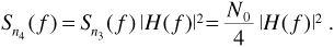
The decision statistic will have a signal component 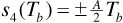 and a noise component n4(Tb). If the matched filter has frequency response H(f), then the power spectrum Sn4(f) of the noise at the matched filter output is
The variance  of the noise component n4(Tb) is
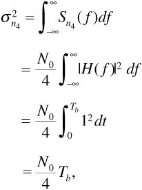
where we used Parseval's theorem to replace the frequency response integral with an impulse response integral. Recall that the probability of error for the system depends on the signal-to-noise ratio
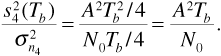
From Equation (6.15) we have the average power in the received signal as Ps = A2/2. The energy per bit is then Eb = PsTb = A2Tb/2. Substituting in Equation (6.23) gives the result
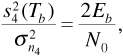
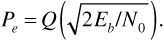
which leads to the familiar expression for probability of error,
Let us now suppose that there is a second user sharing the same carrier frequency. The received signal is

where p1(t) and p2(t) are distinct spreading codes and td is an unknown delay, representing the fact that the two received signals may not be synchronized. Note that we have not explicitly included a message signal m2(t) in the second component of the received signal r(t). To a receiver that does not know the spreading code p2(t), both m2(t)p2(t) and p2(t) appear to be random sequences of Tchip-second rectangular pulses. As these sequences are indistinguishable, we can simplify the notation by omitting explicit reference to m2(t).
After filtering, the signal at point 1 becomes

At point 2 we have

Note that the factor cos(2π fctd) is not a function of time but is a constant that represents the effect of a receiver that is not synchronized to the second user's carrier signal. The receiver next multiplies by the spreading code p1(t), giving

Passing r3(t) through the matched filter gives the decision statistic
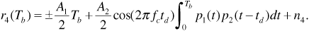
The polarity of the first term in Equation (6.30) depends on the value of the message bit. The second term in the equation represents the interference from the second user, and it is this term we wish to evaluate. Notice the similarity between the integral in this term and the cross-correlation function defined in Chapter 5. In the following discussion we will exploit this similarity to evaluate this term.
From this point the discussion can proceed in two directions, depending on the assumptions we make about the design of the spreading codes. As described previously, we will follow both paths. We first investigate the possibility of designing the spreading codes so that the cross-correlation in Equation (6.30) is identically zero.
In the forward link of a cellular telephone system, a single base station transmits to all of the mobile units in the cell. In this case the carriers and spreading codes of all of the transmitted signals can be synchronized. At any given mobile receiver, all of the received signals arrive with the same delay, particularly if we assume that flat, slow fading is the only multipath effect. To model this case in which received signals intended for distinct users are synchronized, we set the delay parameter td equal to zero in Equation (6.30).
The cross-correlation integral in Equation (6.30) extends from time zero to time Tb. In many spread-spectrum systems the spreading code is designed to appear as a random sequence of chips and hence has a period much longer than the bit time. It is also possible, however, to design short spreading codes. Let us assume that the entire spreading code repeats every Tb seconds, so that each data bit is multiplied by an identical spreading sequence. In this case the integral
is precisely the cross-correlation of p1(t) and p2(t) at zero lag. Two waveforms whose zero-lag cross-correlation is zero are said to be "orthogonal." To support noninterfering multiple users, we seek sets of waveforms that are mutually orthogonal.
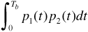
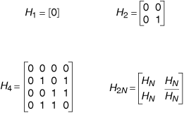
One useful set of orthogonal waveforms is the set of so-called Walsh functions. These are obtained from the rows of the Hadamard matrices. The Hadamard matrices are defined recursively as shown in Figure 6.12. Hadamard matrix H1 consists of a single Boolean zero. To construct Hadamard matrix H2N, form a matrix of four elements. Three of the elements are Hadamard matrices HN, and the element in the lower right-hand corner is the Boolean complement  . Figure 6.12 shows the progression H1, H2, and H4.
Figure 6.12. Structure of the Hadamard Matrices
Once a Hadamard matrix of an appropriate size has been constructed, the Walsh functions are simply the rows of the Hadamard matrix coded as polar-keyed NRZ signals. If the Hadamard matrix HN is taken as the Walsh function generator, then the Walsh functions can be designated 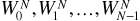 . Figure 6.13 shows the Walsh functions generated by the matrix H4.
Figure 6.13. The Walsh Functions 
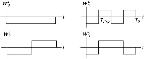
The important attribute of the Walsh functions from our current perspective is that distinct Walsh functions are orthogonal, that is,
Thus we can assign N users to the same carrier frequency and assign each user a separate Walsh function as a spreading code; according to Equation (6.30), each receiver will be able to receive its own assigned signal without interference from any of the other users.
Example
The cdmaOne cellular system is a second-generation system based on CDMA. In the forward link the Walsh functions  are used as spreading codes. Walsh function
  designates the pilot channel, which provides carrier synchronization. There is also a synchronization channel, encoded using Walsh function
  . Paging channels are assigned to the lower-numbered Walsh functions, and the remaining Walsh functions are available for traffic channels.
In the cdmaOne forward link the voice data, including error correction, is provided at 19,200 bits/s. As there are 64 Walsh chips per bit, the chip rate is 1.2288 Mchips/s. The signals are modulated onto a carrier using BPSK and transmitted in a 1.25 MHz channel.
It is very important to be aware that the orthogonality of the Walsh functions is not preserved if distinct functions are shifted in time with respect to one another. Thus in the cdmaOne system, Walsh functions cannot be used to separate users in the reverse channel, where the transmissions from different mobile units, located at various distances from the base station, are harder to synchronize. It is also important to note that not all of the Walsh functions are effective at spreading the bandwidth of the message signal. Walsh function  , for example, does no spreading at all. For this reason, Walsh functions used to separate channels are properly called a cover, rather than a spreading code. In the cdmaOne system, as well as in other systems in which the benefits of bandwidth spreading are desirable, additional spreading using a pseudonoise sequence is employed.
In this section we return to Equation (6.30) and pursue the alternative line of inquiry: We investigate the effect of multiple users sharing a carrier frequency when PN sequences are used as the spreading codes. Recall that a PN sequence is a deterministic binary sequence of finite duration that has the appearance of a random train of bits. The PN sequences used as spreading codes cannot actually be random sequences, however, because a given transmitter-receiver pair must generate the same code in order to communicate. Often, to enhance the appearance of randomness, the PN sequences used have a duration that is very long compared to a bit time.
PN sequences are commonly used to separate users in multiple-access systems when the signals from distinct users cannot be synchronized. In CDMA-based cellular systems mobile stations transmitting on the reverse channel can be difficult to synchronize. Even when a pilot signal transmitted on a forward channel by the base station is used to provide a common clock for the mobile transmitters, the propagation distances from mobile stations to a common receiver at the base station are all different. The propagation differences translate to differences in arrival times for the received signals. We have modeled that unpredictable propagation delay as the parameter td in Equation (6.26).
If p1(t) and p2(t) represent distinct PN sequences in Equation (6.26), then the integral in Equation (6.30) will not be identically zero. Thus we see that the presence of a second user adds interference to the signal we are trying to demodulate. Our immediate task is to quantitatively estimate the amount of this interference. To make this estimate without getting lost in mathematical detail, we will use the simplest model for the interference that is consistent with obtaining a reasonably accurate result. We observe that to receiver number 1, the spreading code p2(t) is indistinguishable from a random sequence of bits. When a delayed version of p2(t) is multiplied by p1(t) and passed through a lowpass (matched) filter, the output is noiselike. We will therefore use a noise model to determine the average power in the interference at the output of the matched filter.
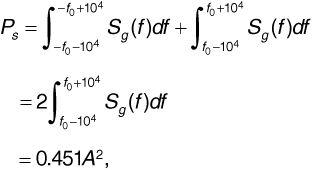
Let us begin with the desired signal. Equation (6.30) gives the desired sample at the matched filter output as  . Squaring this value gives
Now from Equation (6.15), the average power in the desired part of the signal at the receiver input is given by

Combining Equations (6.33) and (6.34) gives

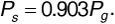
Now let us model the interference. From Figure 6.10 and Equation (6.29) the interference signal at the input to the matched filter is given by
The PN sequences p1(t) and p2(t) can be treated as random sequences of polar NRZ Tchip-second pulses. If we treat the product p1(t)p2(t - td) the same way, then the power spectrum of this product is approximately
This gives the power spectrum of the interference term as
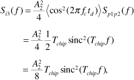
using Equation (6.37) and the fact that  . Now the matched filter in the receiver is essentially a lowpass filter with a bandwidth of approximately 1/Tb. Since 1/Tchip
  1/Tb, the spectrum Si3(f) is very broad compared with the bandwidth of the matched filter. Over the matched filter's limited bandwidth we can take
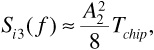
since sinc2(Tchipf)  1 for f 1/Tchip. If the frequency response of the matched filter is H(f), then the power spectrum of the interference at the matched filter output is
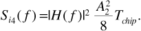
The average interference power at the matched filter output is obtained by integrating Equation (6.40) over all frequencies. We have
where we have once again used Parseval's theorem to replace the frequency response integral with the impulse response integral. The impulse response of the matched filter was given in Figure 6.11. Finally, referring back to Equation (6.26), we see that the average power in the interfering signal at the receiver input is  . Substituting in Equation (6.41) gives
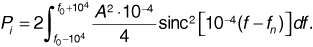
Ultimately, the effect of the interfering signal on system performance can be characterized by the signal-to-noise-and-interference ratio at the matched filter output. If we combine Equations (6.35), (6.42), and (6.22) we obtain
Thus, the signal-to-interference ratio at the matched filter output is proportional to the signal-to-interference ratio at the receiver input multiplied by the spread-spectrum processing gain.
Example
Our derivation of signal-to-interference ratio depends on the assumption that when the spreading code product p1(t)p2(t - td) is applied to a matched filter, the output can be modeled as noise. As an illustration to help make this assumption plausible, two long PN codes were generated, each having a chip duration of Tchip = 1 μs. A segment of the product p1(t)p2(t - td) is plotted in Figure 6.14, where the delay was arbitrarily taken as td = Tchip/4. The product of the two spreading codes was then passed through a filter having a rectangular impulse response of duration Tb, where Tb was taken as 64Tchip. The filter output is plotted as Figure 6.15(a). For comparison, white Gaussian noise having the same power spectrum at low frequencies as the product p1(t)p2(t - td) was passed through the same filter. The output is shown as Figure 6.15(b). A comparison of the two graphs suggests that the noise model for the filtered PN sequence product might be reasonable.
Figure 6.14. A Segment of the Product p1(t) p2(t - td) of Two PN Sequences
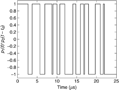
Figure 6.15. (a) Filtered Spreading Code Product Compared with (b) Filtered White Gaussian Noise
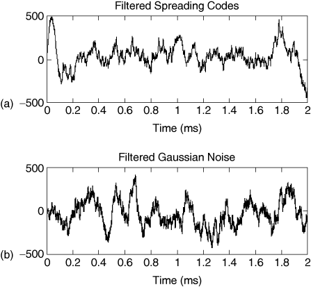
Several important conclusions can be drawn from the signal-to-interference ratio expression given by Equation (6.43). If Ps = Pi, so that the desired signal and the interfering signal are received at the same signal strength, then the spread-spectrum processing gain can reduce the interfering signal to insignificance. If, however, a base station is trying to receive a distant desired signal in the presence of interference from a nearby station, the ratio Ps/Pi can become very small. In this case the processing gain may not be sufficient to overcome the interference. This latter case is an example of the so-called near-far problem. In practical CDMA cellular systems the transmitted power of each mobile unit is carefully controlled so that all signals are received at the base station with equal power. For example, in the cdmaOne system, mobile unit transmitter power is adjusted in 1 dB steps every millisecond to maintain received power equality. For the case in which the desired and interfering signals are received at equal power levels, Equation (6.43) becomes
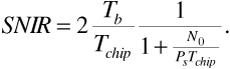
When there are more than two interfering signals, the powers of all of the interference components can be added. If we suppose that K stations share a carrier frequency, each of the stations uses its own spreading code, and all of the signals are received at equal power, then
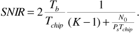
We see that in a direct-sequence multiple-access system the number of users is ultimately limited by the signal-to-interference ratio, just as in a frequency-hopping multiple-access system.
When direct-sequence spread spectrum is used for code-division multiple access in a cellular telephone system, the maximum number of subscribers depends primarily on the allowable signal-to-interference level. Several steps can be taken to reduce the level of interference. First and most important is power control. As we have mentioned in the discussion leading to Equation (6.44), it is essential to ensure that all mobile signals are received by the base station at nearly equal power levels. Power control is not as critical an issue in the forward channel, as signals to all mobile units are sent at the same power level from a single transmitter. A second technique for reducing interference is sectoring. If a cell is divided into three 120° sectors by directional base station antennas, then the number of interfering signals is reduced by a factor of 3. Sectoring thus virtually allows the capacity of the cellular system to be tripled. A third technique for interference mitigation is voice activity detection. It turns out that a speaker in a telephone conversation is active only about 3/8 of the time. Thus, if transmission from each user is interrupted during quiet intervals, the interference power will be reduced by a factor of about 3/8. In practice, a decrease in interference power by a factor of about 2 is realized.
Example
Gilhousen et al.[4] analyzed the capacity of a direct-sequence CDMA cellular system. They assumed a single 1.25 MHz channel, a bit rate of 8 kbits/s from the speech encoder, three-sector cells, and a voice activity factor of 3/8. They characterized propagation by a path-loss exponent of 4 and log-normal fading with a standard deviation of 8 dB. They assumed that with two receiving antennas and an error-correcting code the reverse link requires an Eb/N0 of 7 dB to produce a probability of error of at most 10-3 at least 99% of the time. On the forward link a pilot carrier can be transmitted on a control channel to synchronize the receivers, allowing Eb/N0 to be reduced to 5 dB for the same performance. By modeling the interference from users within a cell, and also from users in nearby cells, they determined that the reverse link can support 108 users/cell. The forward link can support 114 users/cell.
The same study compared direct-sequence CDMA with the AMPS system that uses frequency-division multiple access. For AMPS, a 1.25 MHz band can support just under 42 30 kHz channels. Assuming seven-cell frequency reuse with three sectors per cell, there is a maximum of 6 users per cell. Extending the analysis to USDC, time-division multiple access allows 3 users to be combined in each channel. This gives a total of 18 users per cell. The CDMA system exceeds this capacity by a factor of 6.
Example
Suppose that the reverse link of a certain cellular system has the following attributes for a mobile unit at the cell boundary:
Direct-sequence spread spectrum is used for code-division multiple access. Assume that the modulation is binary phase-shift keying using rectangular pulses. Find the number of subscribers that can be supported per sector.
Solution
For binary phase-shift keying we can relate the probability of error to signal-to-noise-and-interference ratio at the matched filter output by
Substituting Pe = 10-3 gives SNIR = 9.55. This gives the minimum SNIR that the receiver requires.
Next let us calculate the received signal power. From the given data
that is,
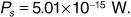
The thermal noise power spectrum referred to the receiver input is
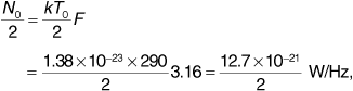
where the noise figure of has been converted out of decibels to give F = 3.16.
Finally, using  seconds and
 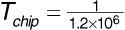 seconds we can substitute in Equation (6.45) to obtain
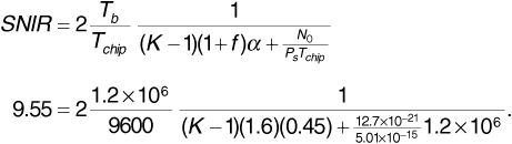
In Equation (6.50) we have multiplied the term representing the total interference power by the factor (1 + f) to account for interference from other cells, and by the factor α to account for voice activity of less than 100%. Solving gives

users per sector.
We conclude by noting that a three-sector-per-cell organization will provide for 99 users per cell. We also note that direct-sequence CDMA can allow all frequency assignments to be reused in every cell. Recall from Chapter 4 that the number of users is larger when the cluster size is smaller. Using a cluster size of one gives an additional enhancement to the system capacity.
In our discussions up to this point we have assumed that access to a channel is granted to a user for an extended duration, and that this access is exclusive. In other words, whether a "channel" is provided by frequency division, time division, or code division, a single user holds possession of that channel for the duration of a call. For direct-sequence CDMA systems we saw that it can be advantageous for a transmitter to cease transmission during pauses in voice activity, but the channel is not reassigned during these pauses. This strategy of long-term channel assignment is based on a "circuit-switching" principle that corresponds to provision of a "circuit" to support a telephone call in the wired telephone network. This strategy makes sense for transmission of voice, video, and other "streaming" signals, in which a user spends a significant fraction of the call duration transmitting data. There are other applications, however, in which data transmission is very different and an alternative switching strategy makes sense.
Consider a data application in which a user transmits short bursts of data at infrequent and irregular intervals. There are many applications for which this kind of bursty transmission is typical. Transmission of e-mail, browsing the World Wide Web, and terminal-based computer activity are applications of this sort. In cellular telephone applications, use of the control (particularly the paging and access) channels is a bursty transmission activity. A mobile unit, when answering or placing a call, sends to the base station a packet of data containing identification and authorization information and perhaps a destination telephone number. These packets are sent only during call setup and hence are sent infrequently. All of these application scenarios share a common feature: It is very wasteful of communication resources to assign a channel on an exclusive long-term basis to a user who sends infrequent, short bursts of data.
The common strategy for providing communication service to users who transmit and receive data in infrequent bursts is to require a number of such users to share a communication channel. User data is presented as "packets," and each packet includes destination and source addresses so that it can be delivered correctly. In many systems there is a maximum allowable packet size, to prevent a single user from hogging the channel for an extended period. This "packet-switching" model characterizes transmission over the Internet, wireless data networks such as those based on the IEEE 802.11 standards, and the control channels of cellular telephone systems.
A major issue for packet-switching systems is how to provide unsynchronized and infrequent users with access to a communication channel in an orderly way. In this section we describe a family of multiple-access methods derived from a simple and elegant procedure called the Aloha protocol first put into practice at the University of Hawaii in the early 1970s. These multiple-access methods are said to be "contention based" for reasons that will become apparent. They are very effective for combining users with bursty data but are most efficient when the aggregate of users only lightly loads the communication channel. We will describe three variations on the contention-based multiple-access theme. We first describe the original Aloha protocol. Then we describe a variation known as "slotted Aloha" that has found application in cellular telephone networks. Finally we describe the "carrier sense" variations that form the basis for wireless data networks. For each of these variations, we will carry out some analysis to determine the efficiency with which the communication channel is used.
The Aloha Network was developed at the University of Hawaii to provide data access to the university's central computer from a number of remote sites. Two radio channels were provided: a downlink to the remote sites and an uplink to the central computer. The multiple-access protocol was needed on the uplink, where there were several stations supporting users with data to send at unpredictable times. The access protocol that was developed for this network is known as the "Aloha" or "pure Aloha" protocol.
An Aloha protocol is very simple. A station (user) with data to send just sends it. Every packet received on the uplink is acknowledged by transmission of a short acknowledgment packet on the downlink. When a station transmits a packet, that station starts a timer. The timer is set so that the acknowledgment should be received before the timer expires, at which point the timer is stopped. If the timer times out, the station assumes that its packet was not received and retransmits it.
Since stations transmitting on the uplink are uncoordinated, it will occasionally happen that two or more stations transmit at once, or nearly at once, so that their packets overlap at the receiver. This occurrence is called a "collision," and a collision normally results in incorrect reception of all of the transmitted packets. In this case there will be no acknowledgments, and all of the stations involved in the collision will time out and retransmit.
Now if two stations transmit at nearly the same time, causing a collision, and both stations time out and retransmit, some mechanism must be provided to ensure that a second collision does not occur. The Aloha protocol requires a station not receiving an acknowledgment to follow a "backoff" procedure. When a station's timer expires, the station generates a random number generated uniformly from a small range of possible values. The station waits ("backs off") a number of time units specified by the random number and then retransmits. A second collision might still occur, but then the procedure is repeated. Eventually the stations involved in a collision will choose random numbers that are sufficiently different that the retransmissions do not collide. Random numbers are used in the backoff procedure instead of fixed assignments in the interests of fairness. Every station has an equal chance of getting its retransmission in first.
We can estimate the efficiency of an Aloha network as follows. Suppose the network has a large number of users who offer packets for transmission at random times and without collusion. Suppose for simplicity that all packets have the same T-second duration. The "offered load" is defined as the number of packets offered to the link for transmission by all users during a T-second interval. The offered load includes packets carrying new data and also packets that are being retransmitted because of collisions and errors. The random backoff procedure ensures that retransmission times are not correlated with the original transmission times, so retransmitted packets are indistinguishable from new packets to the network. Let the offered load be designated by G. The units of offered load are "packets per packet time," or erlangs in telephone terminology.
In Figure 6.16 we show a packet, designated packet 1, transmitted at time t0. Packet 1 is shown colliding with two other packets. Packet 2 was in progress when packet 1 began transmission, and packet 3 is beginning transmission while packet 1 is still in progress. Now to avoid collisions of the packet 1–packet 2 variety, no packet can be offered for transmission during the T-second interval immediately preceding time t0. Similarly, to avoid collisions of the packet 1–packet 3 variety, no packet can be offered for transmission during the T-second interval that immediately follows t0. Thus successful transmission requires that there be an interval of 2T seconds during which no packets are offered to the link for transmission.
Figure 6.16. Packets 2 and 3 Colliding with Packet 1
To calculate the probability that 2T seconds will elapse without an offered packet, we need a model for packet arrivals. It turns out that we can use the same Poisson process model that we introduced in Chapter 4 and described in detail in Appendix B to represent call arrivals at a telephone switch. Equation (B.1) gives us the probability Pk that k packets arrive during an interval of Δt seconds. Repeating the formula here,
where λ is the average packet arrival rate in packets per second. If we substitute λ = G/T and Δt = 2T, we can find the probability P[success] that there is no collision when packet 1 is transmitted. We have
Given the offered load and the probability of success, we can find the rate at which packets are successfully delivered to their destinations. This quantity, which we will designate S, is called the "throughput" by computer network engineers and the "carried load" by telephone engineers. The units of S are the same as those of offered load, packets per packet time, or erlangs. We have
A plot of throughput versus offered load is shown in Figure 6.17. We see that the throughput is at a maximum when G = 0.5. At this offered load the maximum throughput is S = 0.5 e-2 x 0.5 = 0.184. Thus an Aloha network is at most about 18% efficient. For G 0.5 throughput is low because the link is underutilized. For G 0.5 the link is congested, and throughput is low because of an excess of collisions.
Figure 6.17. Throughput versus Offered Load for an Aloha Network
The Aloha protocol has the advantage of simplicity but the disadvantage of making very inefficient use of the communication channel. One enhancement, known as "slotted Aloha," assumes that the time axis is divided into "slots" of length T. Transmission of a packet may commence only at the beginning of a slot. Acknowledgments and backoff are handled exactly as for a pure Aloha system.
To evaluate the efficiency of a slotted Aloha system, consider the scenario shown in Figure 6.18. In this figure the time t0 represents the beginning of a slot. In this scenario, packet 2 "arrived" for transmission during the T-second interval preceding t0. Transmission was delayed until the beginning of the slot, and packet 2 is shown colliding with packet 1. Packet 3, on the other hand, "arrived" during transmission of packet 1. Transmission was delayed until the start of the next slot, and packet 3 does not collide with packet 1. We see that successful transmission of packet 1 requires that there be no packets like packet 2. Packets like packet 3 do not impact the transmission of packet 1. In other words, we require that no packets be offered for transmission during the T-second interval preceding t0.
Figure 6.18. Packet 2 Colliding with Packet 1 in a Slotted Aloha System
As in the pure Aloha case, we use Equation (6.52) to evaluate the probability of a successful transmission. Substituting λ = G/T and Δt = T gives the probability of no collisions as
In this case the throughput or carried load is
Throughput is plotted against offered load for slotted Aloha in Figure 6.19. The slotted Aloha system has the added complexity of requiring synchronization of all of the stations to a common slot clock, but in return, the maximum throughput is about 37%, double that of a pure Aloha system.
Figure 6.19. Throughput versus Offered Load for a Slotted Aloha Network
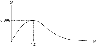
Example
Suppose in a slotted Aloha system that the offered load is G = 1 erlang. To an outside observer, the probability of seeing an empty slot is P0 = e-G = e-1 = 0.368. The probability of seeing a slot carrying only a single packet is  . Then the probability of seeing a slot containing a collision is 1-2 x 0.368 = 0.264. Thus at maximum throughput, about one-quarter of all of the slots carry collisions.
The slotted Aloha protocol is used for control channel access in GSM, USDC, and cdmaOne second-generation cellular systems. Variations on slotted Aloha can be found in third-generation cellular systems both for control channel access and for transmission of packet-based data.
The likelihood of collision in an Aloha system can be reduced if stations with packets to send listen to the channel before transmitting. This operation is called "carrier sense." If the channel is in use, a station must defer before transmitting. A system that implements carrier sense and deferring is called a carrier-sense multiple-access (CSMA) system. Several disciplines govern how long to defer and what to do afterward. These disciplines differ in how aggressive a station is when trying to gain access to the communication channel.
The 1-persistent CSMA discipline offers the least delay in gaining access to the channel when the offered load is very light. When the load is heavy, there will nearly always be a collision when the channel becomes idle following a transmission. It is typical for a transmission to be followed by a "contention period" with multiple collisions. Eventually only one station will transmit. The successful transmission will be followed by another contention period. Nonpersistent and p-persistent CSMA are intended to spread out transmission attempts so that collisions are less likely. The p-persistent discipline can be more like 1-persistent or more like nonpersistent CSMA, depending on whether the value of p is closer to 1 or closer to 0. As an example of the use of these access disciplines, 1-persistent CSMA is the basis of the Ethernet wire-network protocol. A variation on nonpersistent CSMA is used in the IEEE 802.11 (WiFi) local-area network standard. Finally, p-persistent CSMA is used in the packet reservation multiple access (PRMA) system used for combining voice and data in cellular telephone systems.
To illustrate how CSMA improves efficiency over Aloha, we can estimate the efficiency of a CSMA system.[5] Nonpersistent CSMA is the simplest case and the only one we will consider. The random deferral in the nonpersistent case avoids the bunching up of offered packets at the end of a transmission. This allows us to represent the process of packets arriving for transmission as a Poisson process, without having to treat either deferrals or retransmissions in any special way. We will continue to assume that all packets have the same length T. An outside observer would observe that the communication channel experiences busy intervals followed by idle intervals. During a busy interval at most one packet can be transmitted successfully. We will estimate the average duration of a busy interval and the average duration of an idle interval. This will allow us to calculate the average packet transmission rate. We can also calculate the probability that a transmitted packet is successful. This will allow us to calculate the throughput. Let the maximum propagation delay of the wireless channel be tp. A transmitted packet is vulnerable to collisions only for tp seconds after the start of transmission. After this time all other stations will hear the transmitted carrier and defer.
Figure 6.20 shows a collision scenario. Referring to the figure, suppose a busy interval begins at time t0. The transmitted packet, packet 1, lasts T seconds. If there is a collision, the colliding packet will add an additional Δt seconds to the busy interval. Now
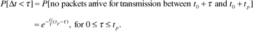
Figure 6.20. Packet 2 Colliding with Packet 1
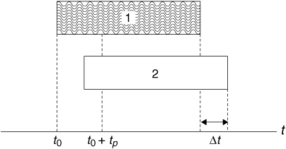
Then the probability density function for Δt is
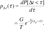
The average value of Δt is then
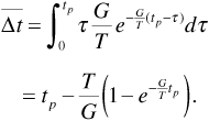
Finally, once transmission of packet 1 and any colliding packets ends, the channel remains busy for tp seconds while the various packets propagate through the link. The total average length of a busy interval is
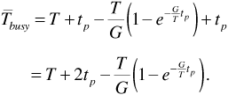
We now estimate the average duration of an idle interval. Suppose a busy interval ends at time t1. An idle interval begins and lasts until transmission of the next packet. Let the idle interval have duration Tidle. The probability that the idle interval lasts longer than  is the probability that no packets arrive for transmission between t1 and t1 + , that is,
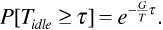
Then
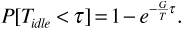
The probability density function for Tidle is given by
The average value of Tidle is given by
Now refer back to Figure 6.20. In that figure only frames of type 1 can be successful. Frames of type 2 are in collision and cannot be successful. Every busy interval begins with transmission of a frame of type 1. The average transmission rate Ravg is
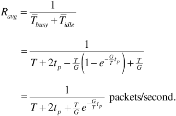
Multiplying by T seconds/packet gives the average transmission rate of type 1 frames in erlangs:
The probability that a type 1 frame is successful is the probability that no frame arrives for transmission during the tp-second interval following time t0, that is,
We can now calculate the throughput S as
The throughput depends on the offered load G and on the ratio of propagation delay to packet length.
When the propagation delay tp is a very small fraction of the packet duration T, the throughput can be very high. In fact, the only reason that S does not approach unity in this case is that the nonpersistent deferral strategy always produces some idle time. When propagation delay is large, however, the throughput can be very poor. For this reason wireless networks using a CSMA strategy are usually limited in geographic size. Figure 6.21 shows throughput plotted against offered load for several values of the ratio tp/T. The Aloha curve from Figure 6.17 is included for comparison.
Figure 6.21. Throughput versus Offered Load for CSMA for Several Values of tp/T
Example
Consider a wireless network that transmits 1500-byte packets at a rate of 10 Mbits/s. The offered load is G = 1 erlang. Find the throughput if the maximum transmission distance is 30 m. Repeat for a distance of 1 km. Finally, repeat for a "national network" of 5000 km.
Solution
For 1500-byte packets at 10 Mbits/s, the packet duration T is given by T = 1500 x 8/10 x 106 = 1.20 ms. For a propagation distance of 30 m, the propagation delay tp is  Substituting in Equation (6.68) gives S = 0.5 erlangs.
For a propagation distance of 1 km we have S = 0.498 erlangs. For 5000 km, S = 32.3 x 10⁻⁹. This example makes it clear why we do not have national CSMA networks!
In a wireless link it is possible that all of the stations cannot hear each other. A station may sense the channel and not hear the carrier of another station that is transmitting. Unfortunately, the receiver may hear both stations, resulting in a collision. This is called the "hidden station" problem. The IEEE 802.11 wireless networking standard includes a number of specialized techniques for dealing with the hidden station problem.
When the data link is from a number of mobile units to a single base station, the base station can send a "busy" or "idle" signal on a control channel that can be monitored by all of the mobile units. When any mobile unit is transmitting, the base station signals "busy." Another mobile unit with a packet to send detects the "busy" signal rather than the carrier of the station that is actually transmitting. This access technique is sometimes known as data-sense multiple access. Data-sense multiple access was used in the cellular digital packet data standard introduced in 1993 to allow first- and second-generation cellular telephone systems to provide data services.
On wire networks such as Ethernet, efficiency can be further improved if stations stop transmitting as soon as a collision is detected. Detecting a collision requires the ability to receive on the transmitting frequency while transmitting, however. As this ability is not common on wireless links, the collision detection option is not available in wireless applications. In Ethernet systems the technique is known as carrier-sense multiple access with collision detection, or CSMA/CD.
Wireless systems such as cellular telephone systems and wireless data networks have the important common attribute that multiple users must share access to the communication medium. An important task for a systems engineer is to maximize the number of users to whom simultaneous service of acceptable quality can be provided. In this chapter we have examined a number of techniques for implementing shared access and compared their relative merits. Our focus for most of the chapter was on methods for providing channels that a subscriber would use for extended periods of time, such as for the duration of a telephone call. In the last section we considered ways of sharing a single channel among users transmitting sporadic, bursty data.
We began the chapter with a high-level overview of how a subscriber obtains access to a voice channel in a cellular system. We described the use of a reverse control channel (universally called an access channel) for this purpose. The access method, at least when described in general terms, is independent of the specific multiplexing scheme that is used to provide voice channels for multiple simultaneous users.
Next we explored three techniques for creating multiple user channels in an overall system bandwidth allocation. The first technique we examined was frequency-division multiple access. Frequency-division schemes date back almost to the beginnings of radio. The overall system bandwidth is divided into disjoint frequency subbands, with each such subband available for assignment to an individual user. The width of each subband, and hence the number of subbands that can be provided, is determined primarily by the bandwidth of the users' modulated signals. Although it seems that the system bandwidth divided by the user bandwidth should give the number of users that can be accommodated, several inefficiencies reduce the maximum number of users in practice. These inefficiencies are primarily a consequence of adjacent-channel interference. The amount of interference experienced is determined by the spectral shaping of the transmitted signals and by the selectivity of the filters used in the receivers.
To illustrate what kind of user density is achievable in practice, we presented several examples of frequency-division schemes. We examined the frequency allocations used in AM radio, an application in which minimizing receiver cost is a primary concern. Next we examined the frequency-division multiplexing scheme developed by AT&T for long-distance telephone communication. This scheme used single-sideband modulation and was characterized by a high level of efficiency. Finally, we reviewed the AMPS first-generation cellular telephone system, whose channel allocations were introduced in Chapter 4.
The second multiple-access method that we examined was time-division multiple access. In this method time is divided into slots, and a number of users take turns using the slots in rotation. Since the users are transmitting sampled data, the slot provided to a given user must become available with sufficient frequency. We saw that application of time-division multiple access to cellular telephone systems did not become practical until speech-processing technology became sufficiently advanced that speech could be digitized at rates below 10 kbits/s.
As is the case with frequency-division multiple access, time-division multiple access is subject to inefficiencies that limit the number of users. These inefficiencies manifest themselves as time slots that cannot be assigned to user data because they are needed for synchronization, transmitter "ramp-up," and other forms of overhead. As illustrations of practical systems we examined time-division multiple access in the voice channels of USDC and GSM cellular systems.
The third multiple-access method, code-division multiple access, offers a higher user density in today's technology than either frequency-division or time-division multiple access and is therefore the method of choice for third-generation cellular telephone systems. We examined frequency-hopping CDMA and direct-sequence CDMA. Direct-sequence CDMA was presented in more detail, as this method is used in both the second-generation cdmaOne and the third-generation cdma2000 and W-CDMA systems. We introduced the Walsh functions as orthogonal spreading codes, and we examined the use of pseudonoise waveforms as nearly orthogonal spreading codes. In the latter case we developed the relation between the number of users and the signal-to-noise-and-interference ratio. This relation allowed us to calculate the number of users that a given system can support.
In the last section of this chapter we examined a different kind of multiple-access problem. In this section we introduced the Aloha, slotted Aloha, and CSMA techniques that allow users generating infrequent bursty data to share a single communication channel. These multiple-access methods are known as "contention-based" methods, because the users compete directly for channel access. The slotted Aloha system has been widely used to provide access to the control channels in cellular telephone systems.
In describing the contention-based access methods we have subtly changed the focus of our discussion of wireless systems. The operation and efficiency of methods such as Aloha, slotted Aloha, and CSMA are not strongly linked to the design of the physical link and can work well on wireless links and on wired links of various kinds. A systems engineer would say that we have moved up a "layer" in our discussion. Providing power to overcome noise, shadowing, and fast fading; designing modulation methods to convey bits with an acceptable error rate and avoid adjacent-channel interference; accommodating many users over a wide geographic area; and providing multiple channels in a given spectral allocation are all aspects of system design at the "physical" layer. The contention-based multiple-access methods, as well as the use of control channels to arrange assignment of traffic channels, are aspects of system design at the "medium-access control" layer. We will encounter layering considerations in more detail in the next chapter, when we examine the kinds of user information that are communicated over wireless systems, how quality of service is specified, and how user information can be packaged for transmission.
When a call is initiated on a wired telephone system, access to the switch is obtained as soon as the handset goes "off hook." The switch receives the dial tones one at a time and proceeds to connect the call when it has all of the necessary digits. In a cellular telephone system, the destination telephone number is keyed into the handset, and access to the switch is not attempted until the "send" key is pressed. Speculate intelligently on why the basic procedure for accessing the switch was changed for cellular telephone systems.
What is the spectrum allocation for the FM broadcast band? What is the channel bandwidth of a single FM station? How close together are FM channels actually assigned in a given location? How many FM broadcast stations are active in your location? You may need to refer to the FCC Web site (www.fcc.gov) for the information you need to answer these questions.
Suppose 400 MHz of spectrum is allocated to a wireless service in which users transmit in 200 kHz channels.
A. How many users can be serviced if a guard band of 50 kHz must be provided between each pair of channels?
B. How many users can be serviced if there are no guard bands, but only every second channel can be used?
The FCC spectrum allocation for mobile telephone service consists of the bands 824–849 MHz for reverse channels and 869–894 MHz for forward channels. Suppose a system consists of one 1.25 MHz CDMA channel and as many 30 kHz AMPS channels as possible. Remember that a guard band of nine AMPS channels must be set aside on each side of the CDMA channel. How many AMPS channels can the spectrum allocation support?
In a certain frequency-division multiple-access system the transmitters transmit data using QPSK modulation with a data rate of 400 kbits/s. Rectangular pulses are used with no filtering at the transmitter. Channels are spaced every 400 kHz. Suppose the receivers use highly selective filters that we can take as ideal brick-wall filters, each having a bandwidth of 400 kHz centered on the appropriate carrier frequency.
Suppose a receiver receives two signals. One of these is the desired signal, and the other has a carrier frequency n channels away from the carrier frequency of the desired signal. The interfering signal is 15 dB stronger than the desired signal.
How large must we make n so that the signal-to-interference ratio is at least 20 dB?
Suppose a voice signal having an absolute bandwidth of 4 kHz is sampled at 8000 samples/second, and each sample is quantized to eight bits. Suppose the resulting bit stream is encoded using a 2B1Q line code.
A. If the line code uses rectangular pulses, find the first-null bandwidth.
B. If the line-code pulse shape is designed for minimum bandwidth, what will be the shape of the pulses? What is the minimum bandwidth?
C. Find the bandwidth if the line code uses raised-cosine pulses with rolloff parameter α = 0.25
In a USDC time slot, what percentage of the time is available for transmission of user data, exclusive of error control bits? What percentage of the slot time is "overhead" (i.e., everything else)?
In a GSM time slot carrying full-rate speech, what percentage of the time is available for transmission of user data, exclusive of error control bits? What percentage of the slot is "overhead" (i.e., everything else)?
A slow-hopping CDMA system uses noncoherent FSK modulation. There are 1000 hopping frequencies and 20 bits of data are transmitted per hop time. Plot probability of error versus Eb/N0 for one, five, and ten users.
A frequency-hopped spread-spectrum system uses 50 kHz channels over a contiguous 20 MHz spectrum. Fast frequency hopping is used, where two hops occur for each data bit. Assume for simplicity that all users hop at the same time. If binary noncoherent FSK is the modulation method used, determine
A. The probability of error for a single user operating at Eb/N0 = 20 dB
B. The probability of error for a user operating at Eb/N0 = 20 dB with 20 other frequency-hopping users sharing the channels
C. The probability of error for a user at Eb/N0 = 20 dB with 200 other frequency-hopping users sharing the channels
A. Find the Hadamard matrix H8.
B. Find and plot the Walsh functions  , assuming a polar NRZ format.
Find and plot the cross-correlation function R37() of Walsh functions  and
and  Assume the Walsh functions are represented in polar NRZ format.
Figure P 6.1 shows a four-stage shift register connected with exclusive-or gates to form a state machine that can generate a PN sequence. The three branches marked with an X may or may not be present, so the figure actually represents eight possible circuits. Imagine that the shift register is preloaded with any nonzero pattern of bits. As the register is clocked, the state machine will cycle through a sequence of states, periodically returning to its original state.
Figure P 6.1. A Four-Bit PN Sequence Generator
A. Prove that regardless of which of the X wires is present, the state machine will eventually return to its original state.
B. Find a set of X connections that will cause the state machine to cycle through all of the nonzero states (the order does not matter) before returning to the original state. Find the corresponding output sequence. This output is a PN sequence. (Note: There are two possible answers.)
C. What output is generated if the shift register is initially in the all-zero state?
The sequences p1 and p2 given below are PN sequences.
p1 = 100010011010111
p2 = 100011110101100
Represent each sequence in polar NRZ format, then find and plot the autocorrelation function R11() and the cross-correlation function R12(). How nearly orthogonal are these two sequences?
A cellular system uses direct-sequence spread spectrum for CDMA. All of the users transmit on nearly the same carrier frequency, and each user is assigned a unique spreading code. Suppose that the spread-spectrum system has a processing gain of 511. Suppose further that there are 63 users transmitting simultaneously in the cell.
A. Find the signal-to-interference ratio at the output of the base station receiver. Ignore thermal noise and assume that signals from all the users are received at the same power level.
B. Now suppose that there are only 2 users. Suppose that the 2 users transmit at the same power level and the path-loss exponent is v = 4. One of the users is 3 km from the base station and the other is 0.5 km from the base station. The base station is attempting to demodulate the signal from the more distant user. Find the signal-to-interference ratio. Ignore thermal noise.
A certain contention-based multiple-access system uses a pure Aloha access protocol. Suppose the offered load is G = 0.4 erlang. An outside observer monitors the communication channel for T seconds, where T is the packet duration.
A. Find the probability that the observer sees no transmissions occur.
B. Find the probability that the observer sees a collision.
A certain contention-based multiple-access system uses a slotted Aloha access protocol. Users transmit at 64,000 bits/s and packets are 1000 bytes long. Find the maximum possible throughput in packets per second.