UPON COMPLETION OF THE FULL-SIZE drawings of the lines for the hull, the builder is at last ready to start cutting wood—be it frames for a sawn-frame boat, molds for a round-bottomed hull, or a male plug for a fabric-reinforced resin or cold-molded wooden hull.
Molds are made from the body plan, and because they are only temporary, they are made from lower grade lumber than that used for the boat parts. Any lumber except hardwood is suitable, the thickness of the molds varying with the size of the boat. A rough guide is ¾″ for boats to 16 feet, ⅞″ for 16 to 24 feet, and 1″ or 1⅛″ for 30-footers. As you will see further along, the molds are set up on the backbone or keel of the boat, and strips of wood called ribbands are bent around the molds similar to planking, except that ribbands have spaces between them. The frames for a round-bottomed boat are bent to shape against the ribbands. There are two schools of thought as to whether the frames should be bent inside or outside of the ribbands, but it will be observed as experience is gained that setting up the frame for the boat is simplified when the frames are bent inside the ribbands. When a number of boats are to be built alike, it is advantageous to make a permanent mold, in which case the frames are bent outside and the mold is removed for further use when the hull has been planked. Also, when a round-bottomed hull is built upside down, the frames are bent on the outside.
The lines for the 12-footer in Figure 7-3, like those for all small boats, are drawn to the outside of planking, and the full-size lines are lofted accordingly. For setups where the frames are bent inside the ribbands, the molds for the sections are made only after the thickness of the planking has been deducted. Similarly, frames for conventional v-bottomed boats are made only after the thickness of planking has been deducted. It should be obvious after you have studied Construction that to make a mold for a round-bottomed boat with the frames bent on the outside of the ribbands, the combined thickness of planking, framing, and ribbands must be deducted from the sections that are drawn to the outside of the planking.
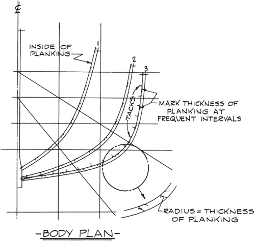
FIGURE 8-1. Planking thickness can be deducted simply by drawing a section that is parallel with and inside the true section, and separated from it at all points by the amount of the planking thickness. However, this is not the most accurate method. The shape of the section will be transferred to the mold stock by pressing the lumber down against the closely spaced tacks (see later in this chapter).
For methods other than conventional wooden Construction, the ways of getting the deductions depend upon the peculiarities of each Construction type. To make a male plug that will be used to form a female mold for a fiberglass hull, only the thickness of the plug planking or covering need be deducted. To make a male mold (or plug or jig—call it what you will) for a so-called one-off fiberglass sandwich hull as described in Chapter 5, “Fiberglass and other Hull Materials,” the deduction must be equal to the outer FRP skin thickness plus the core material thickness plus the ribband thickness. To make a male plug for a cold-molded hull, the deduction must be equal to the total thickness of the hull planking plus the thickness of the plug planking or ribbands.
Countless boats have been built from molds where planking thickness was deducted by simply drawing lines inside the sections by the amount of the planking thickness (Figure 8-1). However, this method is acceptable only when the planking is thin. Let me try to simplify this. If a hole was drilled through the planking, and the thickness of the planking was measured in the hole, the planking would measure correctly only if the hole were at right angles (normal) to the surface of the hull. (See Figure 8-2.) By the same token, such a hole would represent a truly accurate deduction only when the hole itself lies in the same athwartships plane as the stations. Thus, in a shapely hull, the deductions would be fairly accurate amidships, where the plan view waterlines run approximately parallel to the hull’s centerline, but as the waterlines break away sharply toward the centerline as one progresses to the ends of the hull, the deductions would become increasingly inaccurate.
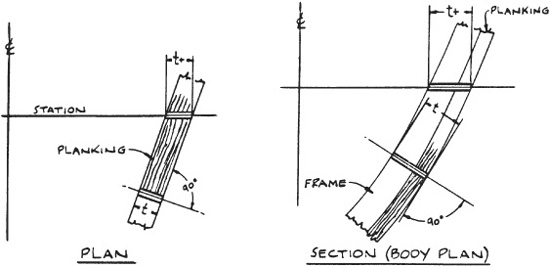
FIGURE 8-2. Deductions for planking thickness are truly accurate only at right angles.
Unless the planking is thin, it is best to take a little more time and make an effort to deduct planking thickness more accurately. To make the thickness deduction almost absolutely correct, it should be done on the diagonals, even to the extent of adding diagonals in addition to those shown on the lines plan, but this chore is not necessary in most cases. Rather than use this procedure, at each station lay off the planking thickness parallel to the waterlines in the plan view of the lines, then pick up this thickness along the station line and transfer it to the body plan, laying it off normal to the section. (See Figure 8-3.) When this has been done at each waterline, take a batten and draw through all the points to get the inside of planking. Once you have done this for a few points, the work will go quite rapidly.
When all the sections have been redrawn to the inside of planking, the molds for a round-bottomed boat can be made (unless additional deductions are required, depending on Construction alternatives, as explained earlier in this chapter). Figure 8-4 shows typical mold Construction, and Figure 8-1 shows how the shape of the section is transferred to the mold stock by pressing the lumber down against closely spaced tacks with their heads laid on the line to be reproduced. Turn the wood over, use a batten to connect the marks made by the tack heads, then work the board to the line. Do this for each station.
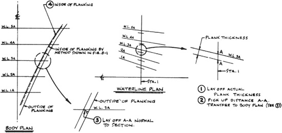
FIGURE 8-3. Deducting planking thickness on the diagonals at each station on the waterline plan and transferring that measurement to the body plan is more accurate than marking planking thickness on the body plan (see Figure 8-1).
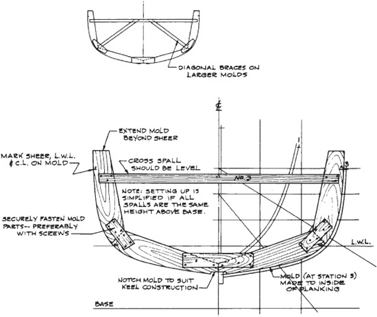
FIGURE 8-4. Typical mold Construction—this mold at Station 3 as seen in Figure 8-1. Molds must be well fastened and braced to retain their shape when set up.
It is not practical to use boards wide enough to get out an entire half mold all in one piece. Plywood of sufficient thickness would be too expensive compared to #2 or #3 solid lumber. Therefore, the mold is made in as many parts as necessary, and laid out in any convenient manner to suit the lumber stock. Just remember that the mold must not be too flimsy. Normally the mold should be extended a half foot or so above the sheerline, but if it is planned to build the boat upside down—a logical method for some small craft—the molds should be extended to a straight baseline above the sheer that represents the building floor. (See Figure 9-1 in Chapter 9.) Depending on the size of the boat, the inverted baseline is made parallel to the waterlines, and at a height enabling the greater part of the hull to be planked from a normal standing position.
Lay the mold parts on the sections of the body plan while carefully fastening them together with screws and butt blocks. Before the half mold is lifted from the plan, mark it at the deck line and L.W.L. For reference while setting up and building. Turn the first half of the mold over so that the butt blocks are down and make a second half to match it. When the mold is assembled, the butt blocks will then all be on the same side. Connect the two halves at the bottom with a block, which should be notched if required by the keel Construction, and fasten a crosspiece, called a spall, at or near the deck line. Spalls on all molds should be level, and if they all are located at the same height above the waterline or base, the molds will be much easier to align when set up on the keel or floor.
The stem assembly is drawn on the full-size lines, either as dimensioned on the Construction plan or, lacking dimensions, from widths scaled from the Construction plan. In boatbuilding language the widths of the stem are the molded dimensions, whereas the thickness of the material for the stem is the sided dimension. Ideally, a stem for a small craft like a dinghy should be made from a natural hackmatack or oak crook as they were some years ago. This is still possible in New England—hackmatack knees are available (see Chapter 4). A template of the stem would be taken to the dealer in this material to select a crook with a shape similar to the stem. But it seems very few people bother with this method anymore.
Often the stem is too large to get out of a natural crook (a range of hack-matack knee sizes is described in Chapter 4), so an assembly of wood will be made up as illustrated in Figure 8-5 or the stem assembly will be laminated. For the amateur, who does not usually count labor, a lamination is often the best way. When an assembly of parts is used, templates of the parts are made, the lines being transferred with tacks as explained for the molds in Figure 8-1. Templates are made of easily worked softwood ⅛″ to ⅜″ thick; ⅛″ or ¼″ plywood; thin plywood “doorskin” veneers; ⅛″ hard-board such as Masonite; or lofting paper (see “The Mold Loft,” Chapter 7). Besides representing the shapes of the parts, the templates must also provide guidelines for rabbeting the stem assembly to receive the planking.
The profile of the rabbet line may or may not be dimensioned on the lines or Construction plan, and even though it is shown, it should be checked full size for accuracy and fairness. The width or half-breadth of the rabbet line is generally the same as the siding of the stem (unless the hull is designed with a round-nosed flaring stem) and either retains a constant width throughout the length of the boat or swells in width toward amidships and then narrows again toward the stern. Bear in mind that the rabbet for planking at the stem, along the keel or horn timber, etc., permits the edge or end of a plank to be square. Reasons for this—caulking, fastenings—will become obvious as you continue to learn how to build a boat.
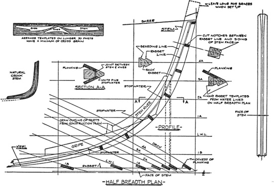
FIGURE 8-5. Plotting the stem and rabbet lines.
It was mentioned before that countless boats have been built from molds made by deducting the thickness of planking by a less-than-precise method, and so it is with the stem rabbet. I will discuss this first and then explain how to lay out the rabbet by a more precise method that consumes but little more time.
Note in Figure 8-5 that the half-breadth of the stem (the half siding—or one-half the thickness) has been drawn as well as the half siding of the face of the stem, and on each waterline half-breadth the thickness of planking has been drawn to get the back rabbet and bearding lines to which the material must be cut. The nomenclature is shown on the section through the stem drawn on waterline 4A in the profile, Figure 8-5. Points to plot these lines on the profile are projected from the waterlines in the half-breadth plan to the waterlines in profile and connected with a batten. The lines for the rabbet and the outline of stem parts are all transferred to the template material at the same time.
The templates are laid out on the stem material and arranged so that there will be a minimum of cross grain in the finished part. Cut and plane the parts to shape (if too heavy for your equipment have a mill do this for you) and lay them out on the full-size lines to check the alignment of the joints in the assembled position. Mark the sheerline, all the waterlines, and the centerlines of the bolts; then bore the bolt holes and put the stem assembly together with an oil-based bedding compound (if you anticipate a day when you may wish to take the assembly apart again) or a polyurethane adhesive sealant such as 3M 5200, Sikaflex 231, or the brushable Sikaflex 251 (if you want a bulletproof joint that will never come apart) generously applied between the faying surfaces of the joints. (Faying surfaces are those in contact with each other.) Whether or not the bolt heads are countersunk and plugged, you should take an extra precaution to make the bolt holes watertight by using a grommet. This is a piece of cotton wicking caulking long enough to go around the bolt a couple of times. In some locales you may hunt in vain for the proper cotton wicking, which is not at all like kerosene lamp wicking. It is available from Jamestown Distributors and Hamilton marine (see Appendix). Apply bedding generously to the wicking and wind it around the bolt beneath the head just before the bolt is driven all the way home. After assembly of the stem, mark the centerline of the boat on the stem and the width of the stem face on each side of the centerline.
Referring to the half-breadth plan in Figure 8-5, make a template of stiff cardboard or thin wood for the rabbet at each waterline. Use the templates to cut a short length of the rabbet at the waterlines, and then complete the rabbet by working away the material between the templated cuts on the waterline. The rabbet may be cut with confidence if the full-size drawing is accurate and complete. However, even some professionals leave the rabbet just a little shallow and complete it when fitting ribbands at the time the boat is set up. In many cases this is because they have learned from experience that their rabbet is not as accurate as it might be. Here is how you can make it more accurate.
In the beginning of Chapter 7 it was stated that vertical sections are drawn at intervals throughout the length of the boat to define the shape of the hull, but it should be realized that sections can be drawn through the hull at any angle, not only at the vertical planes of the stations and buttocks, the horizontal planes of the waterlines, or the diagonal planes. The designer often does this while drawing the Construction plan to get the true, accurate sizes of parts such as the stem assembly; only when a section is drawn normal to the part is full accuracy assured. Since the waterlines and buttocks are the most out-of-normal to the hull surface at the bow (and at the stern of double-ended hulls), it certainly pays to draw auxiliary sections at right angles through the stem of the boat in order to more accurately cut the rabbet.
It is well to note here that for the same reasons of accuracy, bevels should be taken off lines that are normal to the hull surface, or nearly so.
Figure 8-6 has been prepared to show how easy it is to draw sections through the stem (or the sternpost of a double-ender). The sections should be spaced at intervals close enough so that there is no question about having enough of the plotted points for the rabbet, back rabbet, and bearding lines (see Figure 8-5) to ensure a fair line. To save time and effort, the sections should be drawn right on the lines profile, as in section B-B of Figure 8-6, rather than apart as was done for clarity in section A-A.
First a centerline is drawn normal to the face of the stem, long enough to cross enough buttocks and waterlines to give a number of points so a batten can be set up to draw a fair section. For instance, the centerline for section A-A intersects two waterlines and a buttock. Then perpendiculars to this centerline are drawn at the waterline and buttock intersections and at the joints in the stem assembly. (For an illustration of how these perpendiculars can be laid off when the section is drawn directly on the lines profile, see Figure 8-7.) Next the half-breadths at these points of intersection are picked up as in the plan view and laid off on the perpendiculars to establish the points for the section to the outside of planking (section A-A of Figure 8-6). After the section line has been drawn, the thickness of planking is set off, and this sets up the points for the rabbet, back rabbet, and the bearding line.

FIGURE 8-6. A method of drawing sections through the stem.
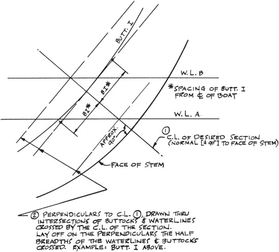
FIGURE 8-7. Setting up the grid for drawing stem sections in place on the profile.
Instead of making templates for the rabbet from the half-breadth plan in the method shown by Figure 8-5, make them from the more accurate sections drawn on the profile as illustrated by Figure 8-6.
Softwood dowels called stopwaters are fitted in joints in the backbone to prevent water from leaking into the hull along the joints. The locations of stopwaters are important for full effectiveness; it is imperative that they be placed wherever the rabbet crosses a joint in the backbone. Any durable softwood such as white pine or cedar will do, and there are so few of them that they can be whittled out of scrap, but they must be as round as the bored hole and a snug fit. Stopwaters are indicated in Figure 8-5 and in larger detail in Figure 8-8. It is tricky to start a drill in the right direction on the surface of the rabbet, so try tacking a piece of softwood on the side of the joint to provide a flat surface (see A in Figure 8-8).

FIGURE 8-8. Stopwaters are extremely important to prevent a leak into the hull wherever a joint in the stem, keel, et cetera, crosses the plank rabbet line.
On the other hand, if you plan ahead it is obviously much easier to drill for stopwaters after the rabbet lines are drawn on pieces like the stem and gripe and before the rabbet is cut.
Stopwaters are recommended even when the joint bedding is one of the highly effective polyurethane adhesive sealants.
Temporary molds are not necessary for the Construction of v-bottomed and arc-bottomed hulls. Instead, the body plan is used to make frames that become a permanent part of the structure. Typical v- and arc-bottomed hull frames are shown in Figures 1-3 and 1-4 in Chapter 1, but these sectional views do not reveal that the bottom and side pieces are beveled so the planking will bear against the entire siding of the frames (see Figure 8-9, A, and Figure 8-10). Note that the bevel—with rare exceptions—is not the same at the sheer as it is at the chine. This makes for more work, but this is the nature of boat hulls. The character, or curvature, of the deck line and chine, etc., determines the amount of bevel. At section B-B in Figure 8-9, where the deck line and chine are approximately parallel to the centerline, it can be seen that there is practically no bevel needed. However, as the deck and chine curve in toward the centerline, forward and aft of B-B, the frames must be beveled.
For a simple boat with straight sections like that shown in Figure 8-9, the bevels can be measured as indicated—the side frame bevels at deck and chine in the half-breadth plan, and those for the bottom frames at chine and keel in the profile. The bevels are cut in a straight line between deck and chine and between chine and keel, respectively. If the frames have some curve, the bevels at major points as described above are just the same, but those for the side frames at points between the deck and chine are taken from the waterlines in the half-breadth plan; those for the bottom frames at points between the chine and the keel are taken from the buttocks in the profile. Bevels for the notches in which the keel, chines, and clamps are fitted are taken off similarly or cut later when the boat is set up. At that time, battens for fairing the frames are run in and bevel adjustments are made by planing the frames.
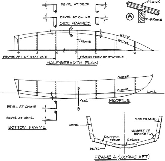
FIGURE 8-9. Making frames for a v-bottomed hull.
To determine bevels with more accuracy, however (and this is very important to time saving in the larger hulls with a good number of frames), the bevels should be measured normal to the surface, much like the deduction for planking thickness previously discussed. This can be done by the method shown in Figure 8-10. The square can be made up by the builder and applied as shown to measure the bevels. Once gotten, the bevels should be marked right on the body plan in degrees for reference and then marked on the actual frame material so that it can be sawn to shape with the proper bevel. The bevels should be taken along diagonals laid out to be as close to normal as possible to all the frames crossed.
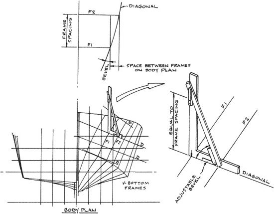
FIGURE 8-10. Bevels should be measured normal to the surface to ensure accuracy, and marked on the body plan and on the actual frame material.
Instead of using a protractor to measure a bevel each time you take one off, make yourself a simple bevel board as shown in Figure 8-11. Use a piece of plywood about 3½″ wide and mark off angles from zero to about 30 degrees. Slide the adjustable bevel along the left edge of the bevel board until it lines up with one of the angles and read it off.
When a bevel is marked on a piece of stock to be sawn, it must be designated as either under or standing, marking the piece UB or SB. This is most important, and after you have ruined a few pieces, you will understand the principle.
Fairing hull lines with the aid of a computer was mentioned in the previous chapter, which dealt with enlarging to full size the designer’s scale drawing of the set of lines defining the shape of the outside of the hull, whether it be wood, metal, fiberglass, or otherwise. Earlier in this chapter it was explained that for round-bottomed hulls, molds are needed to make a male framework on which to shape the frames, and that for v-bottomed hulls frames are needed on which to build the boat. Here is where fairing by computer pays off if your project justifies the expense. A computer-guided plotter can draw full-size sections through the hull (spaced either equally or unequally) at any location desired, complete with deductions from the outside of the hull.
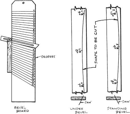
FIGURE 8-11. Make a simple bevel board out of plywood—marking off angles from zero to 30 degrees.
If lofting by computer is used, most of the lofting in the shop is avoided, but the bevels for the edges of the molds or frames will not be available to you. Therefore, you must order bevels from the computer people. Be certain that you understand how the bevels given by the computer should be applied to the section drawings. An explanation will be furnished, along with probably two or three times as many bevels as you really need. There’s just no stopping that computer, but better too many bevels than too few!
The mold spacing for round-bottomed hulls and the frame spacing for v-bottomed hulls is usually at uniform intervals. Sometimes the location of joiner bulkheads, those partitions dividing the cabin accommodations, etc., are not located in the same place as molds or frames. If full-size bulkhead drawings are desired, these, too, can be supplied by the computer service, and once again you should ask for the edge bevels.
Many of the larger boats are built of welded steel or aluminum alloy framing, with a skin or shell plating of the same material. For this type of Construction the computer service can supply full-size drawings, using your scale drawings, from which to cut the frames to shape from flat material, so the drawings should be ordered with the deduction for the thickness of the shell plating.
As will be seen later, the station molds, the stem, and the transom are needed before the boat can be set up. The molds and the stem have been explained, and the development of the transom shape has been illustrated. You also need the bevels on the transom edges. Remember that the developed shape of the transom is to the outside of the planking, and depending upon the type of Construction, it may or may not represent the actual size of the finished transom. The simplest method is to let the side planking overlap the transom and to then cut it flush with the after side. In this case the plank thickness is subtracted from the edges of the transom. The best practice, however, is to make the transom to the outside of the planking and rabbet the edge for the planking. Both methods are shown in Figure 8-12.
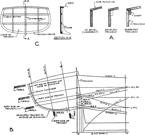
FIGURE 8-12. Transom bevels and typical Construction.
A in Figure 8-12 shows that the inside of the transom is larger than the outside, except at the top edge where the shape depends upon the Construction details, because the boat narrows from amidships to the transom. Consequently, like the frames of a v-bottomed boat, the edges of the transom must be beveled to allow the planks to lie flat. The bevels are taken from the full-size lines as shown—those for the sides from the waterlines in the half-breadth plan and those for the bottom from the buttocks in the profile drawing. But once again it should be remembered that this is not the most accurate way to take the bevels off, because it has not been done normal to the surface of the hull by the method shown in Figure 8-10.
Small-boat transoms are generally made of wide boards whose edges are splined or doweled and waterproof glued. The boards should be sufficiently thick so that the hull planks can be properly fastened to the edge. Such transoms can also be made of marine plywood, with cheek pieces around the edges to take the plank fastenings. Larger transoms, like that shown in C in Figure 8-12, are made the same thickness as the hull planking or thicker and have a frame or cheek pieces on the inside edges to take a share of the plank fastenings. There is usually a vertical member on the centerline, where a wood or metal knee connects the transom to the keel or horn timber. For the sake of appearance, the seams of transom planks should not be caulked. If single planked, the seams of the larger transoms are usually backed with battens. Wide transoms also have a series of vertical stiffeners outboard of the centerline. In a powerboat hull these are frequently spaced to bolt to the ends of long engine stringers.
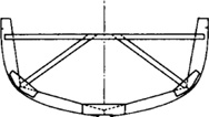
Most transoms do not have enough radius to prevent the planks from being bent cold. In transoms that do have a lot of radius, the planks can be soaked with hot, wet rags or steamed so they will bend to the transom frame.
There are quite a number of keel Construction methods, varying with the type of boat, the preference of the designer, and sometimes with the custom of a particular locality. The types most likely to be encountered are illustrated in Figures 8-13 and 8-14. needless to say, for longevity, only sound timber should go into the backbone members. White oak is the usual material for keel and other backbone members; sapwood should be avoided. Other species of wood can be used as guided by local experience.
The flat-bottomed skiff Construction shown in A in Figure 8-13 and at the top of Figure 1-3 (Chapter 1) is very common. It is mostly built upside down with a few forms notched for the keelson and chines, transom and stem set up and securely braced against movement. Sometimes a rabbeted stem is substituted for the two-piece assembly shown, and some builders like twin keelsons instead of one on the centerline. In a two-piece stem, the side planks are cut off flush with the inner stem, and then the outer stem is fastened to the inner, with sealant applied between the two. Before fastening the keel, cut a slot for the skeg.

FIGURE 8-13. Typical small-boat keels.
The rabbeted keel in B in Figure 8-13 is typical Construction for a great many boats. As was done for the stem in Figure 8-5, the rabbet should be cut at each station from templates and then cut away between the stations to make a continuous fair rabbet for the planking. The amateur will find it easier to make the two-piece keel if he fastens the pieces together over the molds after first beveling them to form the rabbet.
A generous amount of bedding compound should be applied to all backbone joints, as described earlier in the details of a stem assembly. Regardless of the type of backbone structure, this application is important in order to exclude any water between the joined pieces.
A few of the one-design sailboats use a keel without a rabbet, like that shown in C in Figure 8-13. this is all right, but because the garboard plank (the one next to the keel on each side) is not fastened to the keel, care should be taken to attach the frames strongly to the keel. If the frames butt at the centerline, the floor timbers connecting the frame halves must be well fastened to the frames and keel. In way of the centerboard slot in the keel, the bed logs should be thick to make for good fastening through the keel.
The keel structure shown in A in Figure 8-14 is typical of many modern powerboats. The keel is usually the same thickness throughout and is cut to shape from a template made from the full-size profile. A batten bent into place on top forms a back rabbet for the planking. The rabbet is cut the same as for the little boat in B in Figure 8-13. the horn timber aft is rabbeted. A bronze shaft log with packing gland is installed for watertightness where the shaft leaves the hull. The bottom of the keel may be cut away or continued aft and fitted with a skeg to support the bottom of the rudder. The stern end of the keel would be shaped differently if the boat was designed for twin engines.
Note the two-piece wooden shaft log for a single-engine boat shown in Figure 8-14, B. this is easier to make than a log in a single piece, because the shaft hole in each half can be worked out and grooves for splines can be cut on a table saw or with a plow plane. The purpose of the splines is to swell and prevent leaks in the same manner that stopwaters do, and they are made of softwood such as white pine. It is all right to cut through the splines with bolts so long as the bolt holes are tight. the splines swell against the bolts and function just as well as when not cut.
The semicircular grooves that form the shaft hole in a two-piece log can be made on a table saw or even with a portable circular saw by running a series of cuts of varying depths, then cleaning out with a plow plane or “worrying” with gouges. Most professionals prefer two-piece Construction to the struggle of boring out a one-piece shaft log. I strongly recommend a two-piece unit.
It is important to seal the tunnel for the shaft to prevent absorption of water, particularly fresh water, unless the wooden shaft log (B in Figure 8-14) is to be submerged all the time; but if the hull is to be stored ashore, say for several months or so, the moisture content might get in the range where decay can occur. There is more about this in the discussion of propeller shafts and bearings in Chapter 20.
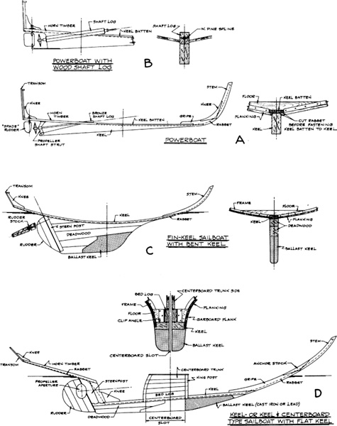
FIGURE 8-14. A few of the many possible backbone structures for powerboats and sailboats.
Fin-keel sailboats up to about 30 feet may have bent keels like that shown in C in Figure 8-14. indeed even larger boats have had this type of Construction, with keels thick enough to need steaming to bend the keel to shape. Probably the easiest way to build a boat of this type is upside down, the keel being bent down over the molds and the fin keel added after the hull is turned over.
Attention must be given to the sequence of the bolting in order to properly fasten the fin. The ballast keel bolts usually extend from the casting through the deadwood, keel, and floors, although sometimes they terminate between frames. The deadwood is carefully shaped as called for by the lines. Although it requires hard work if done by hand (another very good reason to acquire a portable electric plane), a lot of effort should be put into the deadwood to make it smooth and fair, not only for the sake of appearance but also to offer a minimum of resistance as the boat moves through the water. The aft edge of the sternpost is gouged out to take the rudder stock and the rounded forward edge of the rudder. While the forward edge of the rudder can be painted by alternately swinging it hard over to each side, it is impossible to paint the concave edge of the sternpost. To prevent accumulation of marine growth, the after side of the sternpost should be sheathed with light copper sheet brought around on the sides just enough for it to be fastened with tacks, or the groove can be heavily coated with epoxy resin. Either method is acceptable.
The backbone in Figure 8-14, D, is typical of most keel sailboats or combination keel and centerboard sailboats upward of 20 feet on the waterline. The keel in such boats is a thick plank of the same thickness from end to end, but varying in width throughout the length. It is rabbeted for the planking as shown in the section. The vertical position of the keel in the hull structure is drawn in on the full-size profile; then the heights of the keel at the stations it crosses are transferred to the corresponding sections in the body plan to obtain the half-widths of the keel at the stations. A centerline is drawn on the piece of lumber to be used for the keel, the station spacing is picked up and laid off from the full-size profile (the station spacing along the keel is greater than the spacing along the baseline because the keel is at an angle with the base), and the half-breadths of the top of the keel are picked up from the sections and laid off on the keel stock. Draw the outline of the keel with a batten. After the keel is sawn to the shape of the top edge, draw a centerline on the underside of the keel, making sure it aligns with the one on top, and similarly lay off the half-breadths of the keel bottom. The outline of the bottom will give the constantly changing bevel to which to cut the sides of the keel. The rabbet at each section is then templated as a guide for cutting, as mentioned before.
The gripe is the piece that connects the keel to the stem, and the horn timber connects the keel or sternpost to the transom in some types of power and sailboats. Both the gripe and horn timber are very similar to a stem. The rabbet for the comparatively horizontal horn timber is taken from the sections in the body plan. Knees are used to fasten the various backbone members to each other. Much of the backbone Construction work is made clear by Construction sections on the designer’s plans.
The structure between the horn timber and the keel in D in Figure 8-14 and in Figure 10-14, when designed as shown, can be bolted up without fouling the hole for the propeller shaft, but in this arrangement boring a hole for the shaft cannot be avoided. Normally a barefoot auger would be used, with an extension welded to the shank if necessary, and guides devised to keep the hole on course. One source for this auger is W. L. Fuller, inc. It will on request cut off the standard square end, leaving a round shank that is best powered by nothing less than a ½″ electric drill. A heavy-duty “hammer-drill” that hammers while it revolves may reduce the boring time, but I have never tried the tool in this application.
After all the backbone members are shaped, but prior to fastening them together, it is recommended that they be given two coats of a wood preservative. These preparations are inexpensive and well worth the investment for their rot preventive qualities. The liquid should also be poured down the bolt holes before the fastenings are driven. through-bolts and drift bolts, described at length in Chapter 6, are made and fitted as shown on the Construction plan for the boat, and the fastenings must be studied for sequence so the assembly will go together properly. It will be seen as you go along that some of the bolts cannot be driven at this time because they pass through floor timbers (Figure 8-14, A and C) That are not made and fitted in the structure until later. Once again it must be emphasized that all joints have bedding so that no crevices are left for water to seep through or to collect in and possibly start to rot the timbers. Under the washers of through and drift bolts it is advisable to wind a few turns of cotton wicking soaked in paint before the bolts are finally driven home. Very often this treatment will prevent leaks that otherwise would be troublesome or at least annoying. Wicking and a source for it were discussed earlier in this chapter under “Stem and Rabbet.” The stopwaters mentioned earlier are fitted after the parts have been bolted.
It is not always possible to obtain pieces of wood long enough for the keel, deadwood, bilge stringers, clamps, and shelves. Fortunately, sufficient lengths may be found for keels more often than for the other parts, even though an extensive search is required. The backbone requires enough work of the builder without his having to splice the keel, particularly the type shown in D in Figure 8-14. When it cannot be avoided, the long members are pieced out by means of through-bolted joints called scarphs. Nowadays these joints in wood are often glued with an adhesive such as resorcinol or a highly water-resistant glue such as thickened epoxy for good measure. If not glued, the joints must be bedded. Bolts are staggered when thickness of lumber permits.
Figure 8-15 illustrates three types of scarphs commonly in use, and it should be noted that all have nibs to prevent one part from slipping by the other when under strain. The joint shown in A is the very common plain scarph that is extensively used for stringers and clamps. The hooked scarph, B, is sometimes employed in backbone members. Just as effective, and easier to make, is the key scarph shown in C. This is simply a plain scarph mortised to take a tightly fitted rectangular key, preferably of durable wood like white oak. In large timbers the key is sometimes made of two wedges driven from both sides at the same time and cut off flush with the sides of the timbers. Such wedges are made with a taper of about one-half inch to the foot.
The scarph with feather edges at the top of Figure 8-15 is marked “incorrect,” but if such a joint is properly fitted, adequately clamped, with a couple of nails temporarily driven (to prevent skidding out of alignment when pressure is applied), and glued with a waterproof or highly water-resistant adhesive, then this joint is satisfactory. For an adhesive I would probably use epoxy, thickened to avoid starving the joint. This material is gap-filling and does not require as much pressure as a resorcinol glue. A polyurethane adhesive sealant is a good alternative.

FIGURE 8-15. Common scarphs for joining long members such as keels, clamps, and stringers.
The scarphed joints and their fastenings may not be shown on the boat plans or specifications. A rough rule for the scarph length is six times the depth of the timber, while the keys and nibs are made up to one-fourth of the depth. If the inexperienced builder should not be able to locate a piece of wood large enough for the keel, the designer or a competent boatbuilder should be consulted for the layout of scarphs most suitable for use with the available material.
The mortise-and-tenon joint is sometimes called upon to lock adjoining members having grain perpendicular to each other. The joints between the vertical sternposts and the keel in D in Figure 8-14 are typical. When the wood is not too thin, the tenon is made blind—that is, only partway across the pieces—and therefore it is not visible when the parts are fitted together. Whatever the case, the joint must be made as snug as possible and put together with bedding on the mating parts.