HVAC & Appliances
In this chapter:
• Maintaining Gas Forced-air Heat Systems
• Maintaining Hot Water & Steam Heat Systems
 Maintaining Gas Forced-air Heat Systems
Gas forced-air systems are widely used in cool climates worldwide. A gas forced-air furnace—running on natural gas or liquid propane (LP)—draws in surrounding air, channels it across a set of heated plates, known as a heat exchanger, and then uses a blower to circulate the air throughout the house (illustration). A chamber on top of the furnace, known as a plenum, leads the warmed air from the furnace to a network of ducts that carry the warm air to heat registers or vents mounted on walls or ceilings. To keep the cycle going, return ducts carry cooled air from each room back to the furnace so it can be reheated and recirculated. Older systems use gravity to carry warm air throughout the house and cool air back to the furnace.
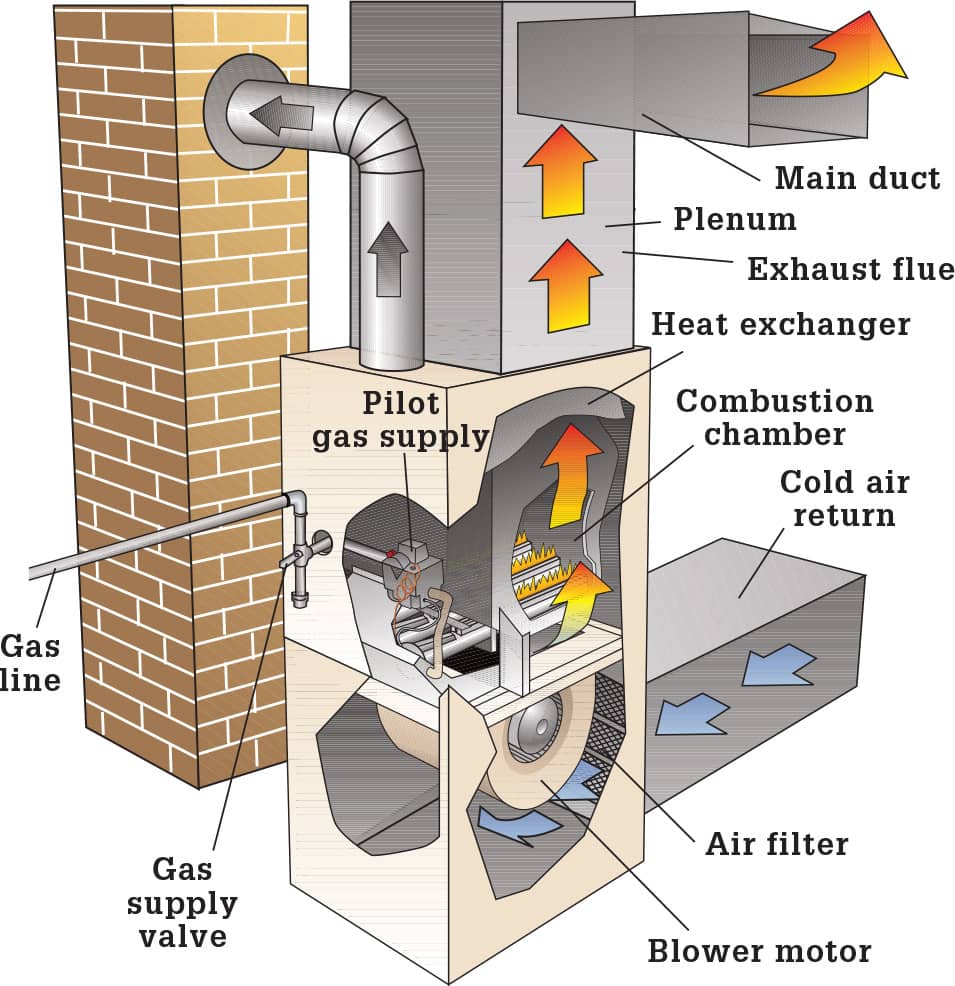
Identifying the plenum and cold air return, as well as the main duct leading to the rooms in your home, is a good way to begin familiarizing yourself with your forced-air system.
Balancing a Forced-air System
Most forced-air systems have dampers within the ducts that let you control how much air flows to various parts of the house. These are separate from the registers used to manage airflow within each room. Adjusting the dampers is called balancing the system.
Start by locating the dampers (illustration). When a damper handle or wing nut is parallel to the duct, it is wide open, allowing maximum airflow. When the handle is perpendicular to the duct, it is closed.
To balance your system, start by setting the thermostat as you would for the times when you’re at home. Close the dampers that lead to the room with the thermostat. Wait a few hours, and go to the rooms that are farthest from the furnace. If those rooms are too warm, leave them until later, when more dampers are open. Check the other rooms for comfort. After each damper adjustment, wait a few hours for the air temperature to stabilize.
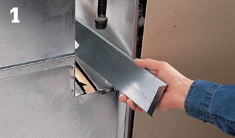
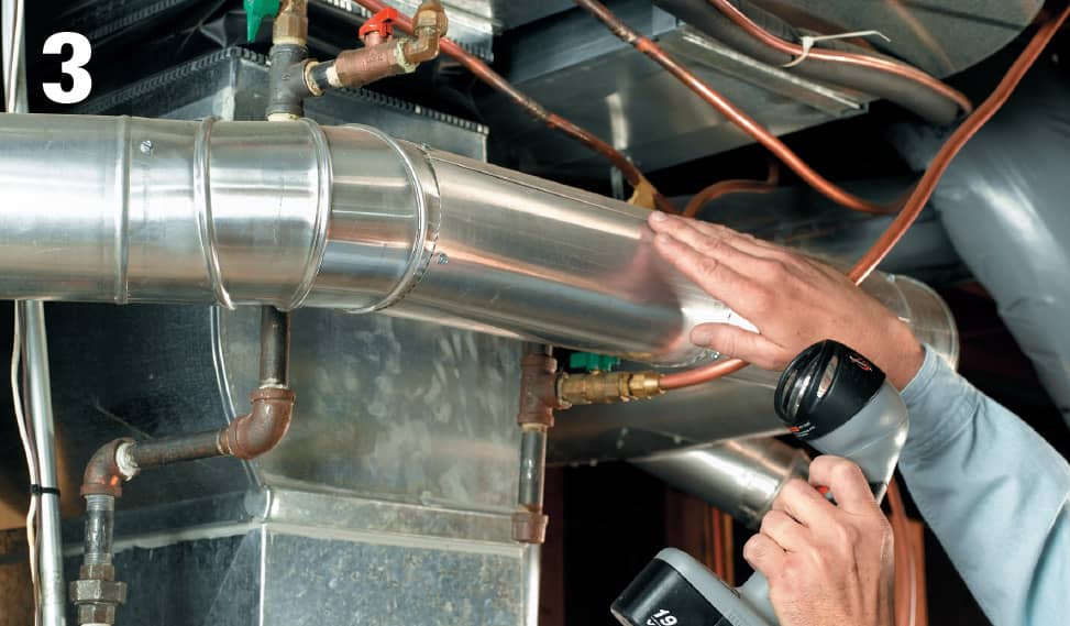
Once you’re satisfied with the heat each room receives, use a permanent marker on each duct to indicate the correct setting for each damper (photo 1). Repeat the process in the summer for air conditioning, making a second set of marks to indicate the correct damper settings for cooling.
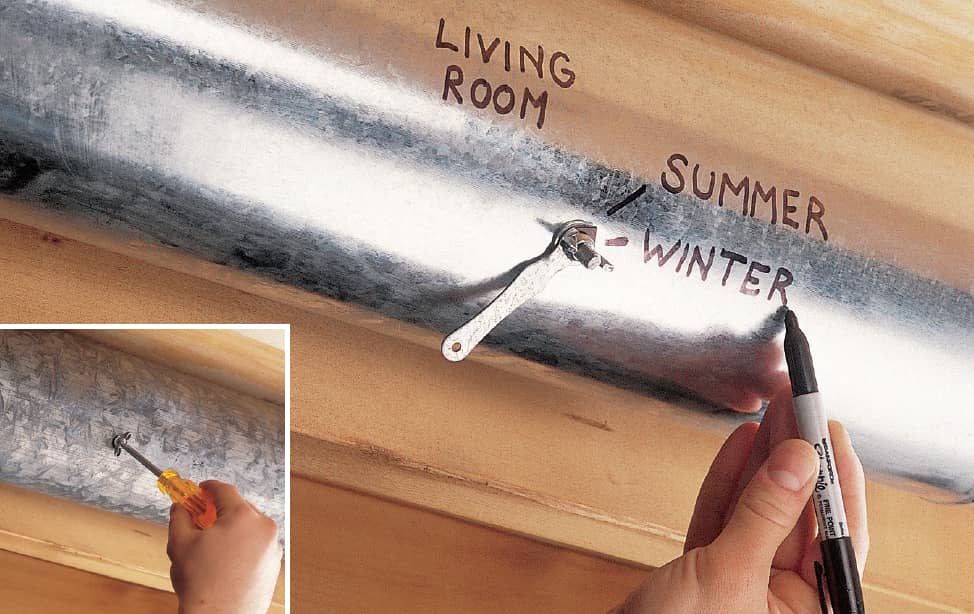
Mark damper positions on each duct, and indicate which room is affected by the settings. Open or close the damper using a screwdriver or by turning the wing nut (inset).
Maintaining a Forced-air System
You can handle most routine furnace maintenance yourself. Generally, the newer the furnace, the simpler the maintenance, since a number of heavy-maintenance components have been eliminated on newer models.
Most furnaces installed since the 1980s do not have a thermocouple-controlled pilot light. In fact, the standing pilot light found on older furnaces has been eliminated completely. In most cases, it’s been replaced with either an intermittent pilot light that’s lit only when there’s a call for heat from the thermostat, or a glowing element, known as a hot-surface igniter. An intermittent pilot light must be repaired by a professional technician, should it fail. You can replace a hot-surface igniter yourself.
Use this section to identify and complete the maintenance procedures that apply to the furnace in your home.
Before doing any maintenance, always turn off the furnace’s main gas supply and the pilot gas supply, if your furnace has a separate one. Then, switch off the furnace’s main power switch and the power to the furnace at the main service panel. Check your owner’s manual for any warnings or special instructions concerning your furnace. Then, clear the area, so you have a safe work space.
Start with the most important and simplest furnace maintenance procedure—inspecting the air filter. There are many types of filters. Read the section below to find out how to clean yours and how often it must be changed.
Replacing the Air Filter
The air filter on your forced-air furnace is designed to capture dust, pollen, and other airborne particles. The filter must be cleaned regularly, according to the manufacturer’s specifications, and should be inspected once a month. Locate the filter compartment and remove the access cover (photo 1). The location of the compartment depends on the furnace type and the style of filter. Many filters fit in a slot between the return air duct and blower. A few styles are located inside the main furnace compartment. An electrostatic filter is installed in a separate unit attached to the furnace.
Slide the filter out of its compartment, taking care not to catch it on the sides of the blower housing. Hold the filter up to a light (photo 2). If the filter blocks much of the light, replace it. Electrostatic filters can be reused after cleaning.
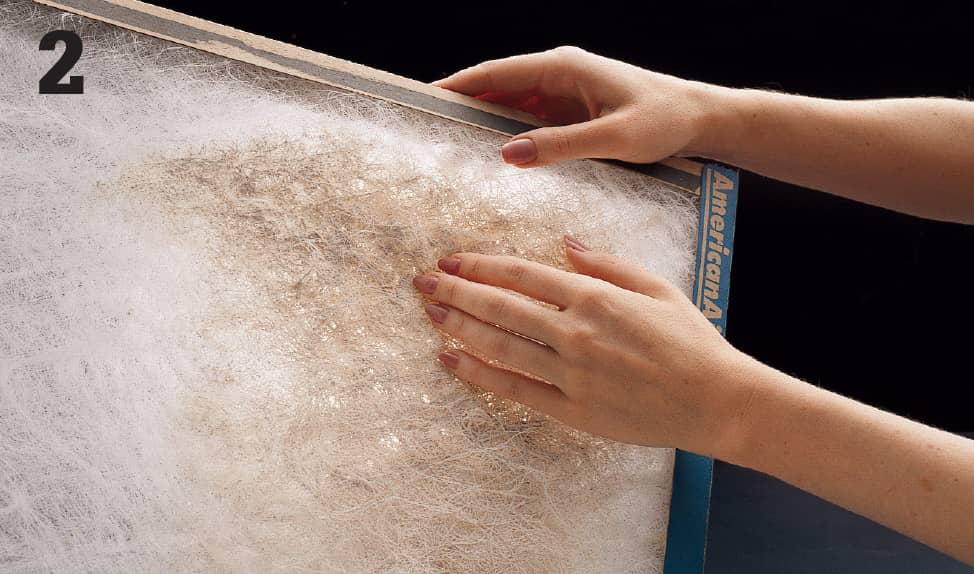
Hold the filter up to a bright light for inspection.
Maintaining the Blower Motor
Inspect the blower motor before the start of the heating season. Inspect it again before the start of the cooling season if your central air conditioning uses the same blower.
Turn off the power to the furnace. Remove the access panel to the blower housing and inspect the motor (photo 1). Some motors have oil ports and an adjustable, replaceable drive belt. Others are self-lubricating and have a direct-drive mechanism. Wipe the motor clean with a damp cloth and check for oil fill ports. The access panel may include a diagram indicating their location. Remove the covers to the ports (if equipped) and add a few drops of light machine oil (photo 2). Place the covers on the ports.
With the power still off, inspect the drive belt. If it is cracked, worn, glazed, or brittle, replace it. Check the belt tension by pushing down gently midway between the pulleys (photo 3). The belt should flex about 1". To tighten or loosen the belt, locate the pulley tension adjustment nut on the blower motor (photo 4). Loosen the locknut, and turn the adjustment nut slightly. Check the belt tension, and readjust as required until the tension is correct.
If the belt is out of alignment or the bearings are worn, adjusting the tension will not solve the problem. With the power off, hold a straightedge so it’s flush with the edge of both pulleys (photo 5). To align the belt, locate the mounting bolts on the motor’s sliding bracket (photo 6). Loosen the bolts, and move the motor carefully until the pulleys are aligned. Tighten the bolts and check the tension and alignment again. Repeat until the pulley is aligned and the tension adjusted. Replace the furnace access panels. Restore power and switch on the furnace.
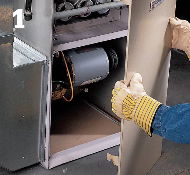
Remove the access panel to the blower housing and inspect the motor.
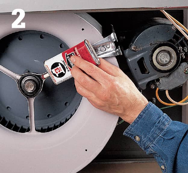
Remove the covers to the oil ports and add a few drops to each port.
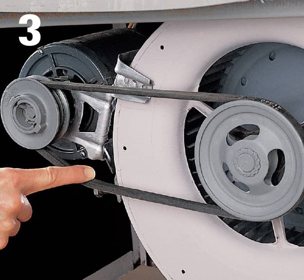
Check the tension by pushing down on the middle of the belt.
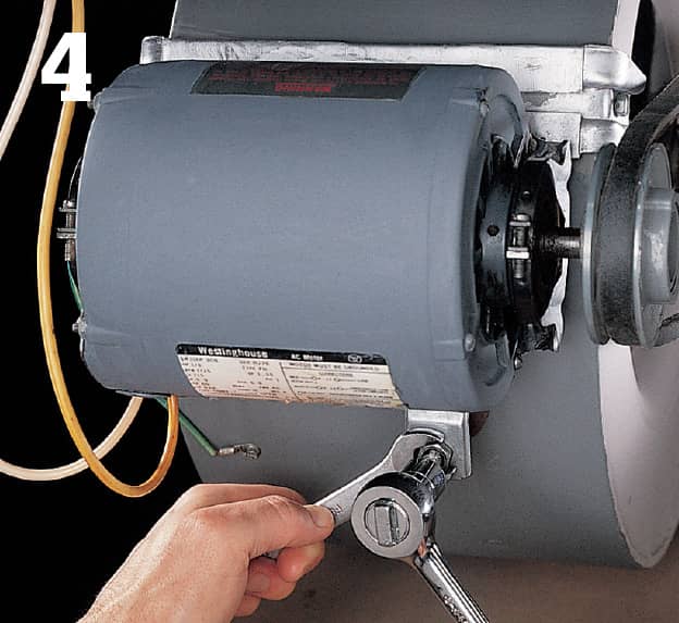
Loosen the pulley tension adjustment nut slightly to tighten the belt.
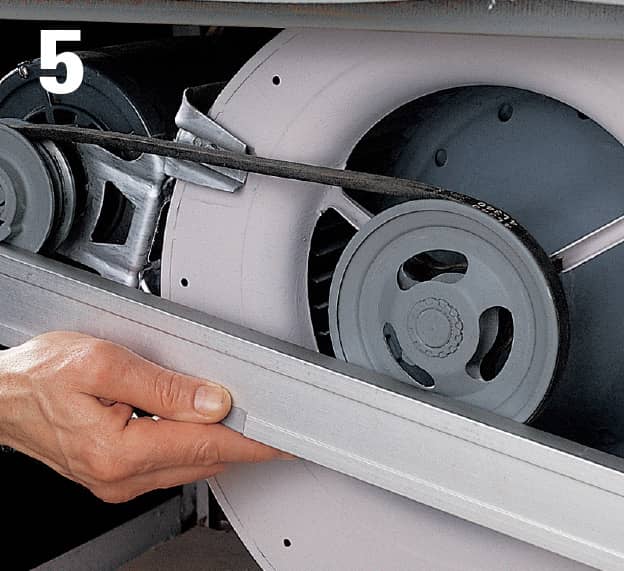
Check the pulley alignment, using a straightedge.
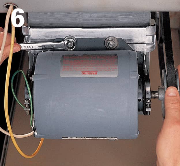
Loosen the bolts that hold the motor on its sliding bracket, and move the motor carefully until the pulleys are aligned.
Inspecting the Pilot & Thermocouple
The pilot light (it’s actually a flame used to ignite gas flowing through the burners) plays a large role in the efficiency of the entire system, and a clean-burning pilot saves money, improves indoor air quality, and extends furnace life.
If your furnace has a standing pilot light, always check the flame before the start of the heating season to ensure that it’s burning cleanly and with the proper mix of air and fuel. Start by removing the main furnace access panel. If you can’t see the pilot flame clearly, turn off the gas supply (photo 1) and the pilot gas shutoff switch (if equipped). Wait 10 minutes for the pilot to cool, and remove the pilot cover. Relight the pilot, following the instructions on the control housing or access cover. If the pilot won’t stay lit, shut off the gas supply once again and inspect the thermocouple.
Inspect the flame (photo 2). If the flame is too weak (left flame), it will be blue and may barely touch the thermocouple. If the flame is too strong (center flame), it will also be blue, but may be noisy and lift off the pilot. A well-adjusted flame (right flame) will be blue with a yellow tip, and cover 1/2" at the end of the thermocouple. Turn the pilot adjustment screw (photo 3) on the control housing or gas valve to reduce the pressure. If it’s weak, turn the screw in the other direction to increase the pressure. If the flame appears weak and yellow even after adjustment, remove the pilot jet and clean the orifice (page 500).
If the pilot in your furnace or boiler goes out quickly, and you have made sure the gas supply is sufficient, you may need to replace the thermocouple. Turn off the gas supply. Using an open-end wrench, loosen the thermocouple tube fitting from the control housing or gas valve. Unscrew the thermocouple from the pilot housing and install a new one (photo 4). Tighten it with a wrench just until it’s snug.
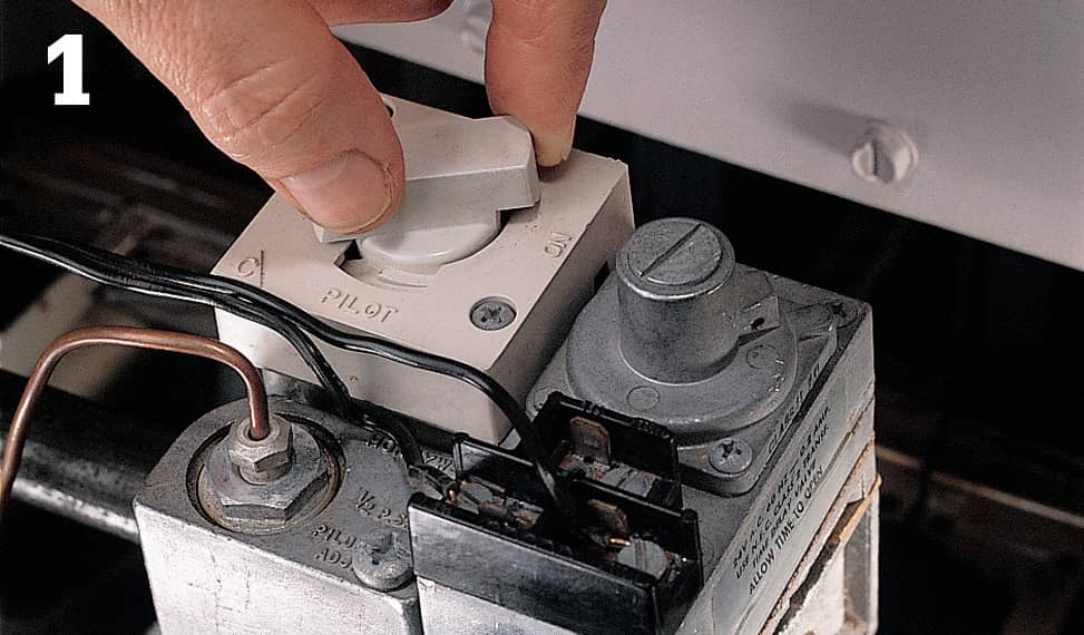
Turn off the main gas supply and the pilot gas supply (if your furnace has a separate one).
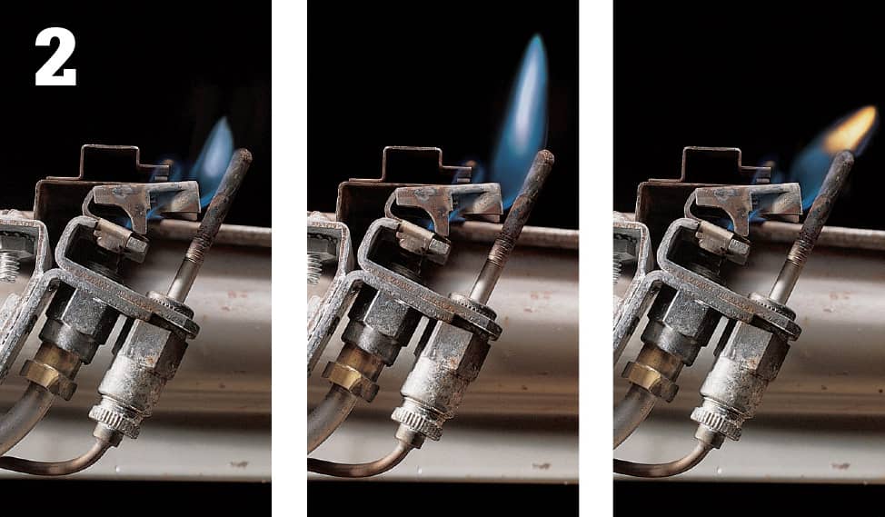
Adjust the flame so it is steady, has a yellow tip, and covers the thermocouple’s tip (right).
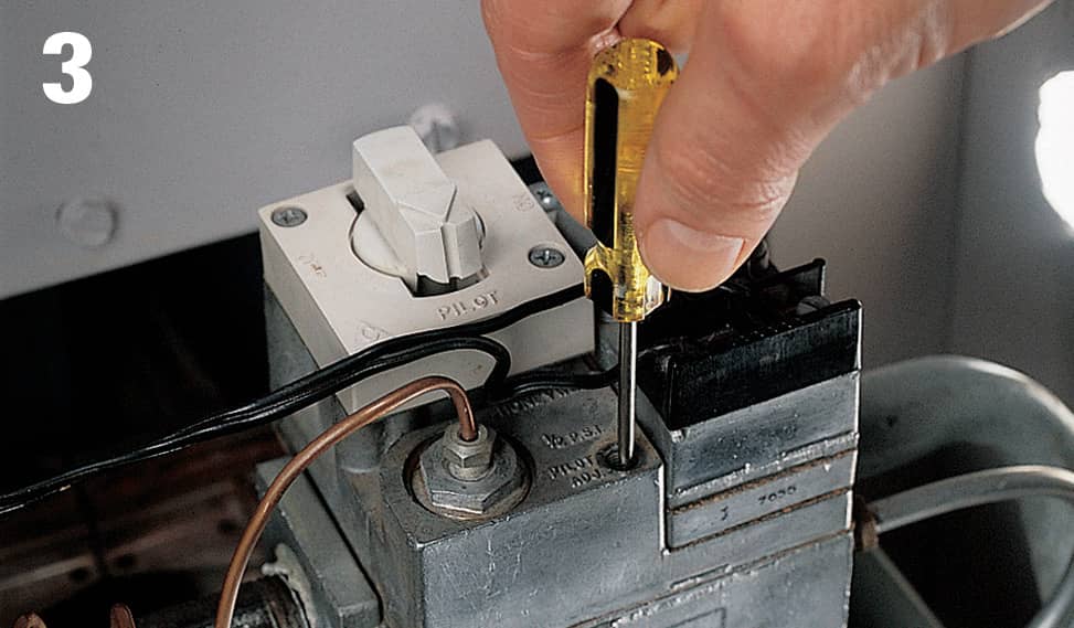
Turn the screw to adjust the height of the flame so it covers the top of the thermocouple.
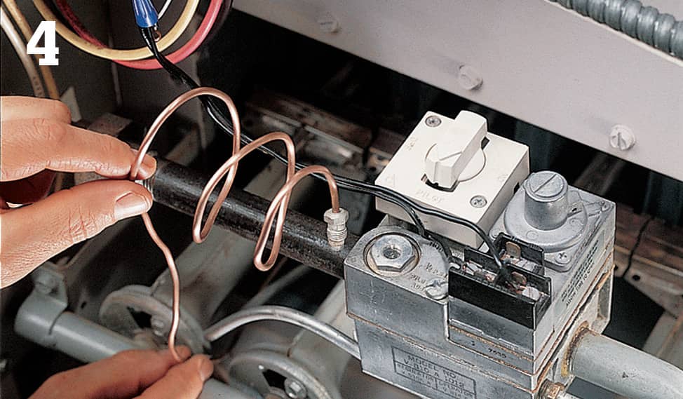
Remove the thermocouple from the control housing and install a new one.
Cleaning & Adjusting the Pilot Light
If the thermocouple and burners in your furnace or boiler appear to be working correctly, but the pilot flame is inconsistent or weak, remove the pilot jet and clean or replace it. Turn off the power and close the gas supply, including the gas supply to the pilot if your unit has a separate one. Wait at least 30 minutes for the parts to cool. Using an open-end wrench, remove the thermocouple from the pilot housing (photo 1).
Use two wrenches to hold the gas line in place, then loosen the nut that connects it to the control housing. Unscrew and remove the pilot housing, then carefully remove the pilot jet from the housing (photo 2).
Clean the outside of the pilot jet with a parts brush, and carefully clean the inside with a pilot jet tool. Take care not to scratch the inside of the jet, as this will affect its performance. If the pilot jet is severely corroded or difficult to clean, replace it.
Thread the pilot jet back into the pilot housing, and reinstall the housing. Reattach the gas line, turning the connecting nut while holding the line steady. Reinstall the thermocouple. Reopen the gas supply and turn the power back on, then light the pilot.
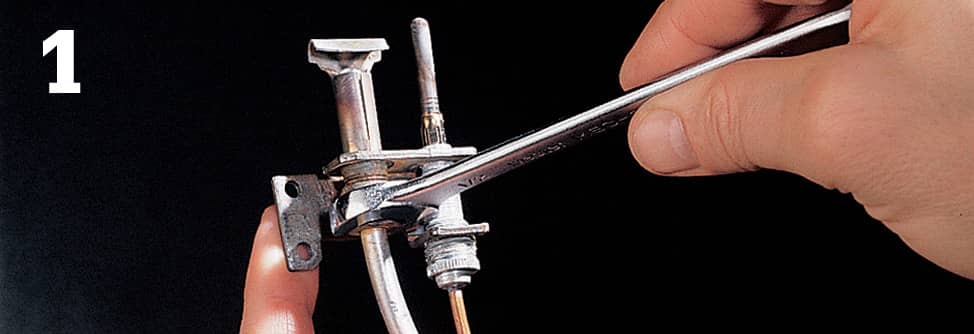
Loosen the connecting nut on the gas line with an open-end wrench.
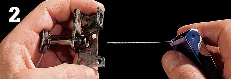
Remove the pilot jet from the housing and clean it with a pilot jet tool.
Inspecting the Burner Flame
Once you’ve set the pilot flame, check the burner flame. The burner flame should be blue, with a bluish green flame at the center and occasional streaks of yellow (photo 1). If it appears too blue or too yellow, adjust the air shutter at the end of the burner tube (photo 2). Start by setting the thermostat high so that the furnace continues to burn. Wearing protective gloves, loosen the air shutter locking screw. Open the shutter wide, then close it slowly until the flame color is right. Retighten the locking screw. Repeat the procedure for each remaining burner. Reset the thermostat.
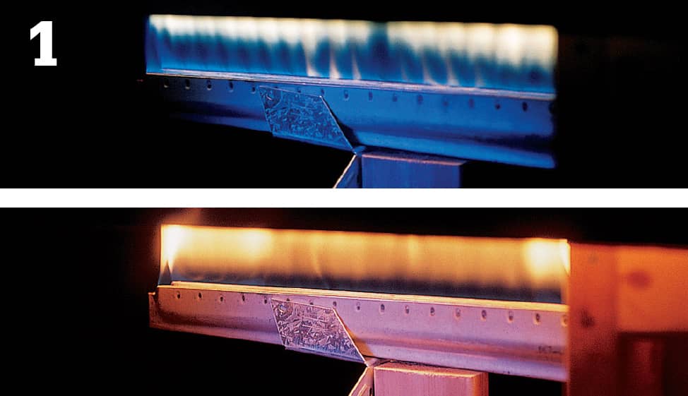
Compare your burner flame with the two above. Yours should be blue-green, with streaks of yellow (top).
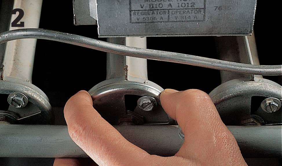
If the shutters are adjustable, you can set them yourself. Otherwise, call a professional for service.
Cleaning the Burners
Burners work by mixing together gas and air that is then ignited by a pilot flame or a heated element. Gas is delivered by a manifold and enters each burner tube through a small orifice, known as a spud. Burners and spuds gradually become encrusted with soot and other products of the combustion process and must be cleaned occasionally to keep them working efficiently.
To clean the burners, turn off the furnace’s main shutoff, and switch off the power to the furnace at the main service panel. Shut off the gas supply, including the pilot gas supply if your unit has a separate one. Wait at least 30 minutes for the parts to cool. Remove the burner tubes by unscrewing them from their retaining brackets (photo 1), by pulling out the metal pan that holds them, or by loosening the screws that attach the gas manifold to the furnace. On some furnaces, you need to remove the pilot housing to reach the burners.
Twist each burner carefully to remove it from its spud (photo 2). Fill a laundry tub with water and soak the burners. Carefully clean the outside of the burner tubes and the burner ports with a soft-bristled brush. Replace any tubes that are cracked, bent, or severely corroded.
Inspect the spuds: clean burners won’t work effectively if the spuds are dirty or damaged. Use a ratchet wrench to loosen and remove each spud (photo 3). Clean the outside of each spud with a soft-bristled brush. Then, use a pilot jet tool to clean the inside of each spud (photo 4). The tool is designed for cleaning small orifices, but take special care to avoid scratching or enlarging a spud’s opening. Reinstall the spuds in the manifold. Tighten them just until they’re snug. Once the burner tubes are dry, install them on the spuds, and attach them to the burner tube brackets or burner pan. Connect the pilot housing, if equipped. Turn the power and gas supply back on. On furnaces with a standing pilot, relight the pilot flame.
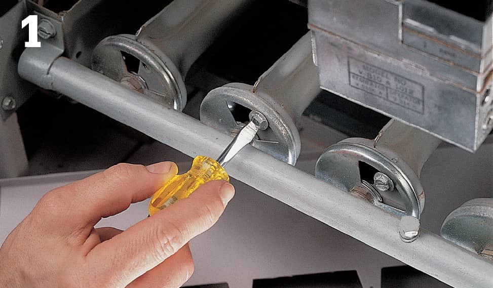
Remove the screws holding the burners to their brackets or to a slide-out pan.
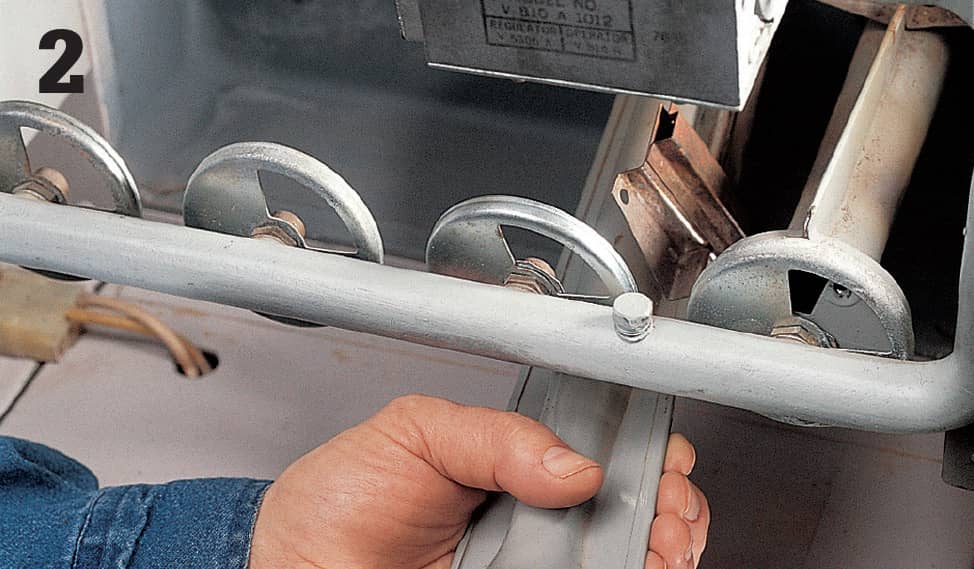
If a burner is difficult to remove, twist it carefully from side to side while lifting and pulling.
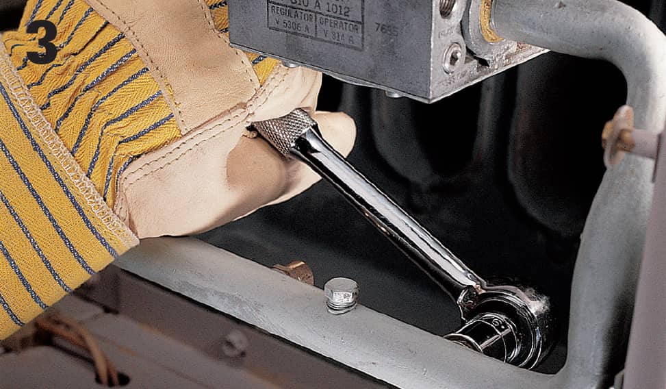
To avoid bending or damaging the spud threads, hold the manifold steady with one hand as you remove each spud.
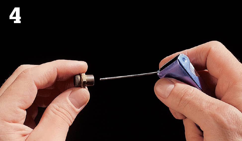
Clean each spud orifice carefully with a pilot jet tool, taking care not to scratch or enlarge the orifice.
Servicing Electronic Ignition Furnaces
Newer furnaces include an intermittent pilot light or hot-surface igniter as well as an electronic control center, with warning lights to help you recognize problems.
On some newer models, the temperature difference between the supply and return ducts needs to be within a narrow range to avoid damaging the heat exchanger. To find out whether this applies to your furnace, check the information plate on the burner compartment—it may include an indication of the acceptable range.
Each season, check the differential by slipping the probe of a pocket thermometer into a slit in an expansion joint in the supply duct (photo 1). Record the reading and compare it with the temperature in the return air duct. Call a professional technician if the difference between the two numbers falls outside the recommended range.
Your furnace may contain an intermittent pilot, which is lighted with a spark when signaled by the thermostat. An intermittent pilot consumes gas only when necessary, reducing home fuel costs. If the electronic ignition fails to spark, call a technician for service.
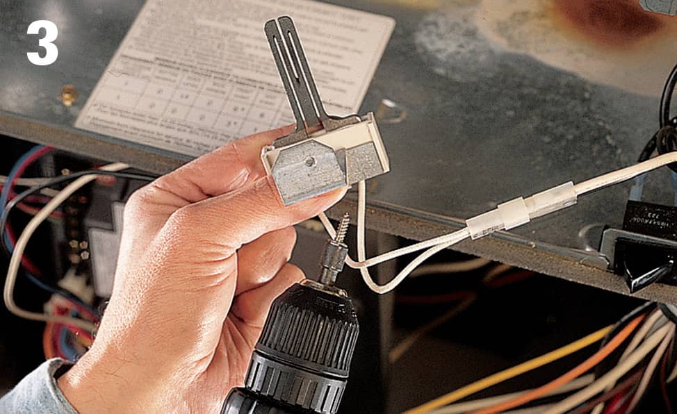
Some furnace models ignite the gas with a glowing element, known as a hot-surface igniter. If the igniter fails, replace it. Remove the main furnace panel and locate the igniter just beyond the ignition end of the burner tubes. Disconnect the igniter plug and remove the nut on the mounting bracket with a nut driver or ratchet wrench (photo 2). Replace the igniter.
If the igniter still doesn’t function properly, check with the manufacturer: you may need to replace the control center. Detach the wires from the old control center one at a time and attach them to the replacement (photo 3). Then, disconnect the old control center, using a screwdriver, and connect the new one (photo 4).
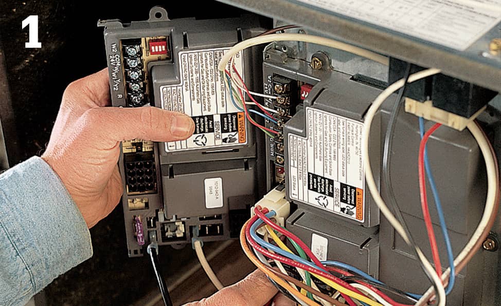
Remove the control center wires one at a time and switch them over to the new control center.
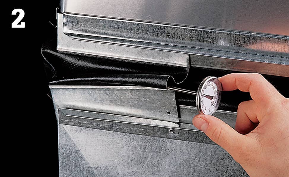
Check the temperature inside the supply duct and compare it with the temperature in the return duct.
Disconnect the faulty hot-surface igniter from the mounting bracket.
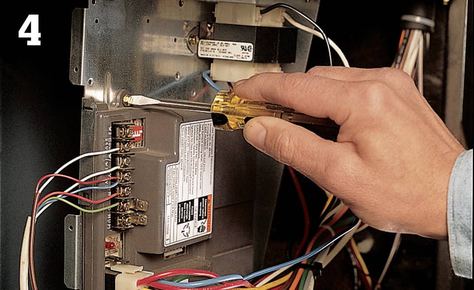
Unscrew the control center’s mounting screws and install the replacement unit.
Maintaining a High-efficiency Gas Furnace
A high-efficiency gas furnace is defined as a furnace that’s at least 90% “efficient,” as determined by an annual fuel utilization efficiency (AFUE) rating.
Furnaces made as late as 1992 can have ratings as low as 60%. A standard, mid-efficient unit sold today is about 80% percent, while high-efficiency units can be as high as 96% efficient.
Like other furnaces, high-efficiency gas furnaces require maintenance. The air filters must be cleaned regularly—electronic filters need to be cleaned on a monthly basis, and disposable filters should be changed every three months (photo 1).
If the drain line cannot drain properly, moisture can build up inside the heat exchanger and restrict gas flow. Inspect the drain line to make sure it’s free of kinks. Some furnaces have several drain connections that should be inspected.
Clean the drain line once a year by disconnecting it from the furnace and forcing water from a garden hose through the line (photo 2). If the drain line is black plastic, remove it at a connection point, then reattach once it’s clean. If the line is white, then it’s PVC, and you’ll need to reconnect it to the unit with a coupling after cleaning it.
Some furnaces have a removable condensate trap. If your unit has one, remove it at the beginning of the winter season and clean it out with water. Check the trap periodically throughout the season and dump the water as necessary.
Check the vent pipes and furnace unit for signs of corrosion (photo 3). The water produced by the furnace is acidic and will corrode metal quickly. If pipes are leaking, they must be replaced.
Make sure the areas around the air intake and exhaust are unobstructed. Plants, bushes, and other materials that block the intake and exhaust can cause the furnace to shut down (photo 4).
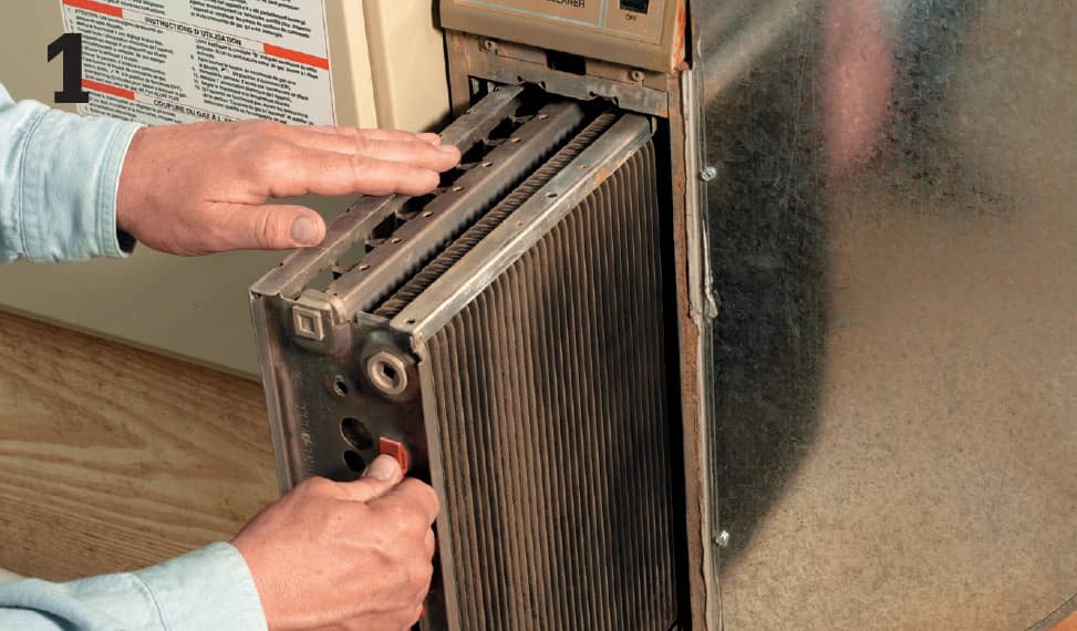
Clean electronic filters every month, then reinsert them in your furnace.
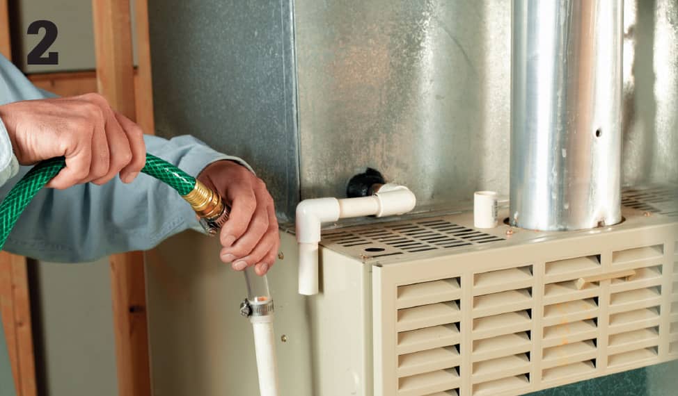
Clean the drain line once a year by running water through it from a garden hose.
Inspect the areas around vent pipes for signs of corrosion. Corroded pipes will need to be replaced.
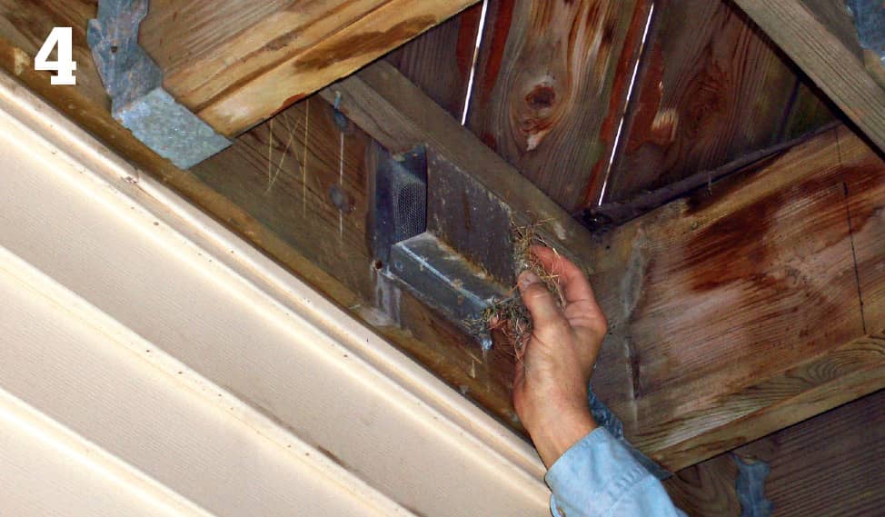
Remove any debris and materials that could block the air intake and exhaust.
 Maintaining Hot Water & Steam Heat Systems
Hot water and steam systems, also known as hydronic systems, feature a boiler that heats water and circulates it through a closed network of pipes to a set of radiators or convectors. Because water expands and contracts as it heats and cools, these systems include expansion tanks to ensure a constant volume of water circulating through the pipes.
Hot water and steam systems warm the surrounding air through a process called convection. Hot water radiators (photo 1) are linked to the system by pipes connected near the bottom of the radiator. As water cools inside the radiator, it is drawn back to the boiler for reheating. The radiators in steam systems (photo 2) have pipes connected near the top of the radiator. These radiators can be very hot to the touch. Convectors (photo 3) are smaller and lighter and may be used to replace hot water radiators, or to extend an existing hot water system.
Although the delivery of hot water or steam to the rooms in your house is considered a closed system, some air will make its way into the system. Steam radiators have an automatic release valve that periodically releases hot, moist air. Hot water radiators contain a bleed valve that must periodically be opened to release trapped air. It is usually necessary to bleed convector systems using a valve near the boiler.
Today’s hot water and steam systems are often fueled by natural gas. Older systems may use fuel oil. Fuel oil systems require more frequent maintenance of the filter (page 529) and blower (page 530).
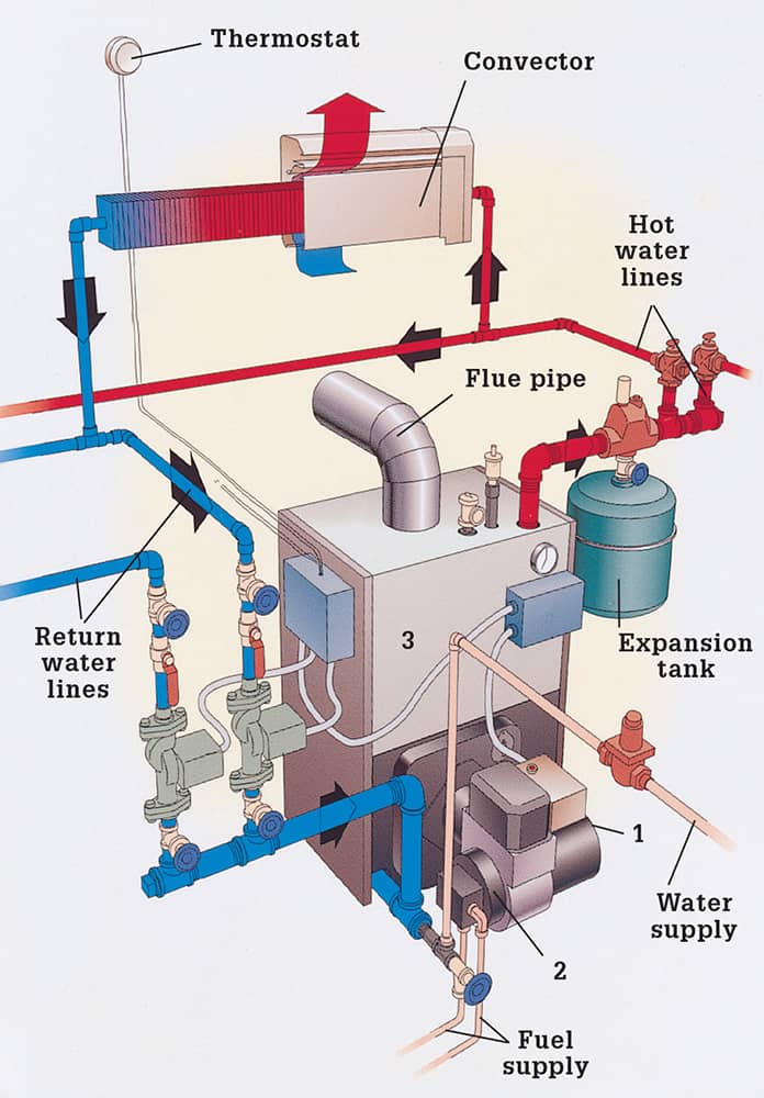
A blower draws in air through the air intake (1) while a fuel pump (2) maintains a constant supply of fuel oil. The mixture is ignited by a high-voltage spark as it enters the combustion chamber (3) and heats water.
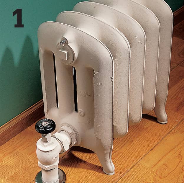
Hot-water radiators circulate heated water through pipes. As it cools, water is drawn back to the boiler for reheating.
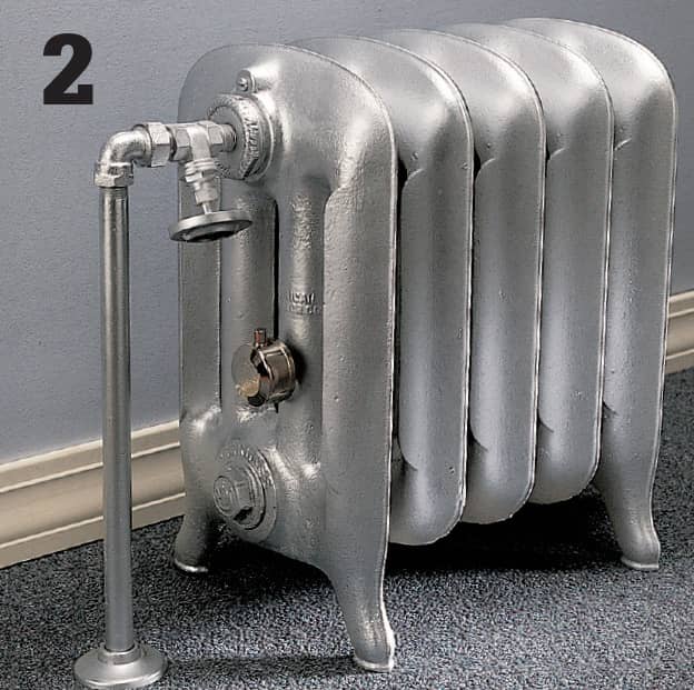
Steam radiators operate at a higher temperature. Steam cools in the radiators, returns to a liquid state, and then flows back to the boiler.
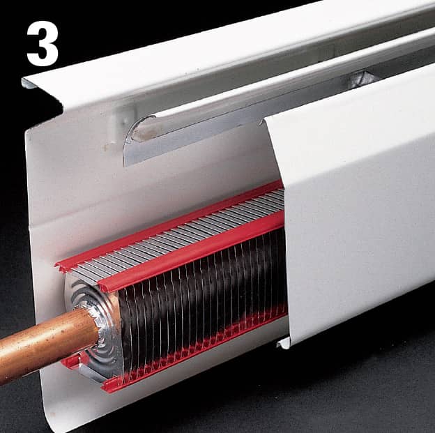
Space-saving hot water convectors work on the same principle as radiators, but use thin sheet-metal fins to transfer heat to the air.
Servicing the Oil Filter & Strainer
Replacing the oil filter is the best routine maintenance you can do for your hot water or steam heating system.
Surround the base of the boiler with a drop cloth and newspaper. Shut off the power to the boiler at the main service panel and at the boiler shutoff switch, usually located near the boiler. Then, close the fuel line supply valve and wait 30 minutes for all parts to cool.
Wearing disposable gloves, unscrew the top of the filter cartridge (photo 1). Remove the cartridge with a twisting motion and turn it over to dump the old filter into a plastic bag (photo 2). Remove the gasket from the cartridge and wipe out the inside, first with a cloth dipped in solvent, then with a dry cloth. Install a new filter and gasket (photo 3). Position the cartridge under the cover and screw it back in place.
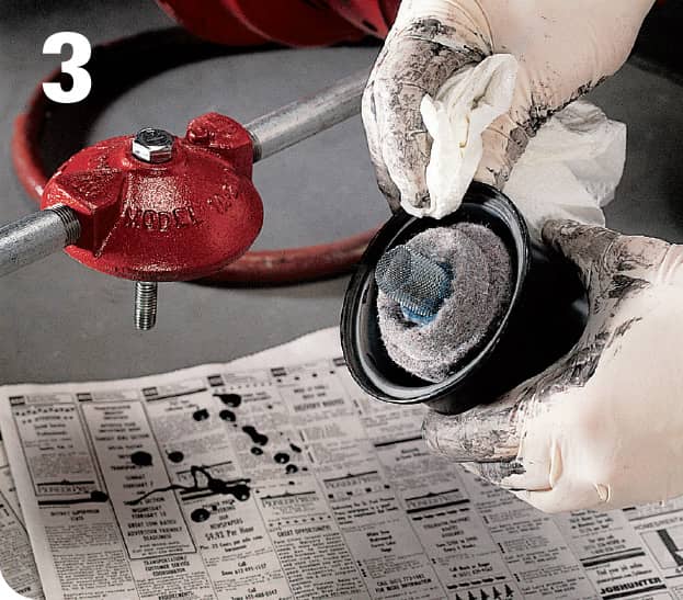
Use an open-end wrench to remove the bolts from the pump cover (photo 4). Leave the oil line attached, and remove the gasket and mesh strainer from the cover (photo 5). Clean the strainer with solvent and a parts brush. If it’s badly worn or damaged, replace it. Wipe the cover with a clean cloth. Place the clean strainer or replacement strainer in the cover and install a new gasket. Fasten the cover bolts in place. Restart the boiler.
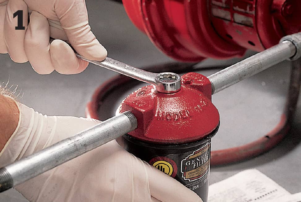
Have a disposable plastic bag ready, and unscrew the top of the filter cartridge.
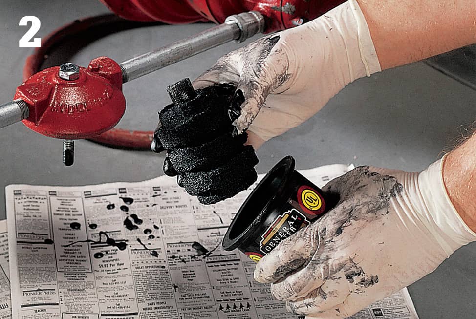
Twist the cartridge to remove it from the oil supply line. Ask your waste removal company for disposal instructions.
Wipe the edge of the cartridge, first with a solvent-dipped rag and then with a dry rag.
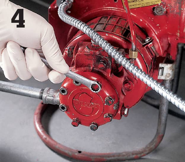
Leave the pump cover attached to the fuel line when you remove it.
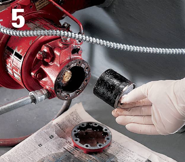
Remove the mesh strainer carefully. Even a heavily soiled one can often be reused after a good cleaning.
Cleaning & Lubricating the Blower
Clean fuel and a reliable air supply are critical to your boiler’s performance. Clean the air intake on your boiler every month and lubricate the motor every two months during the heating season.
Turn off the power to the boiler. Brush any dust and debris from the air intake with a narrow, medium-bristle brush (photo 1). Use an open-end wrench or screwdriver, as required, to loosen the transformer. With the transformer still attached, move it aside to reach the blower fan (photo 2). Use the brush and a damp cloth to remove dirt and debris from the fan blades (photo 3).
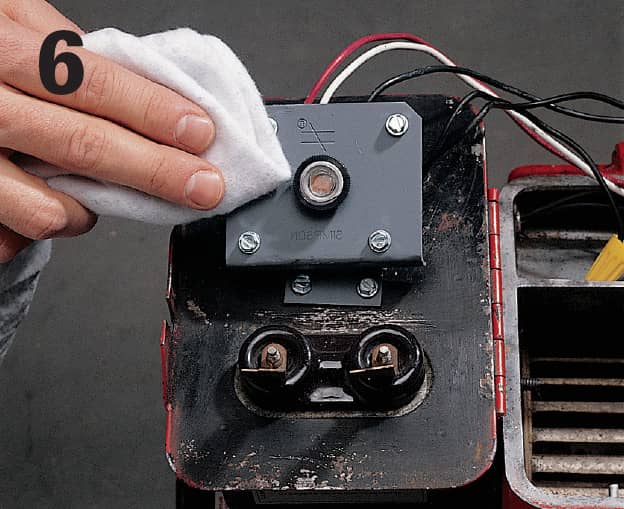
Most boiler blowers have a port on top or cups at each end for adding lubricating oil. Check your owner’s manual or consult the manufacturer on the best lubricating oil for your blower. Before removing the plugs or opening the cups, clean the outside of the motor with a damp cloth (photo 4) to keep dirt and debris from getting into the motor. Remove the plug from the opening or the lid from each cup, using a wrench or screwdriver, as required. Add a few drops of lubricating oil (photo 5).
If the motor doesn’t have oil ports or cups, it’s probably a self-lubricating type (photo 6). Check your owner’s manual to be sure.
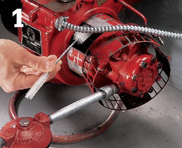
To clean the air intake, use a brush designed for cleaning the condensing coils on a refrigerator.
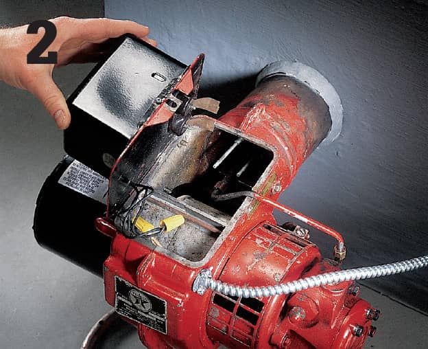
If the transformer attaches to the blower housing with a hinge, simply swing it out of the way. If it comes loose, be careful not to strain the wire connections.
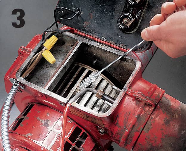
The blades on most blower fans are thin and hard to reach, so use a long brush carefully: a bent fan blade makes much more noise than a dirty one.
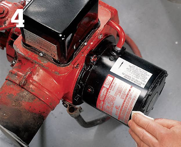
To prevent dust or dirt from getting in the motor while you add oil, clean off the surface with a damp cloth before opening the ports or cups.
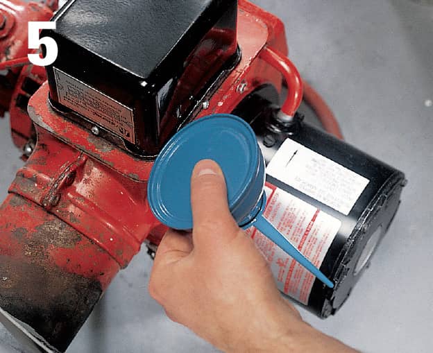
Add lubricating oil to the ports or cups. The motor housing may indicate what kind of oil to use.
If the motor doesn’t have cups or openings for adding lubricating oil, it’s probably sealed and may not need extra lubrication.
Draining & Filling a System
Sediment gradually accumulates in any water-based system, reducing the system’s efficiency and damaging internal parts. Draining the boiler every season reduces the accumulation of sediment. Be aware that draining the system can take a long time, and the water often has an unpleasant odor. This doesn’t indicate a problem. Drain the system during warm weather, and open the windows and run a fan to reduce any odor.
Start by shutting off the boiler and allowing the hot system to cool. Attach a garden hose to the drain at the bottom of the boiler (photo 1), and place the other end in a floor drain or utility sink. Open a bleed valve on the highest radiator in the house (page 508).
When water stops draining, open a bleed valve on a radiator closer to the boiler. When the flow stops, locate the valve or gauge on top of the boiler, and remove it with a wrench (photo 2).
Make sure the system is cool before you add water. Close the drain valve on the boiler. Insert a funnel into the gauge fitting and add rust inhibitor, available from heating supply dealers (photo 3). Check the container for special instructions. Reinstall the valve or gauge in the top of the boiler, close all radiator bleed valves, and slowly reopen the water supply to the boiler.
When the water pressure gauge reads 5 psi, bleed the air from the radiators on the first floor, then do the same on the upper floors. Let the boiler reach 20 psi before you turn the power on (photo 4). Allow 12 hours for water to circulate fully, then bleed the radiators again.
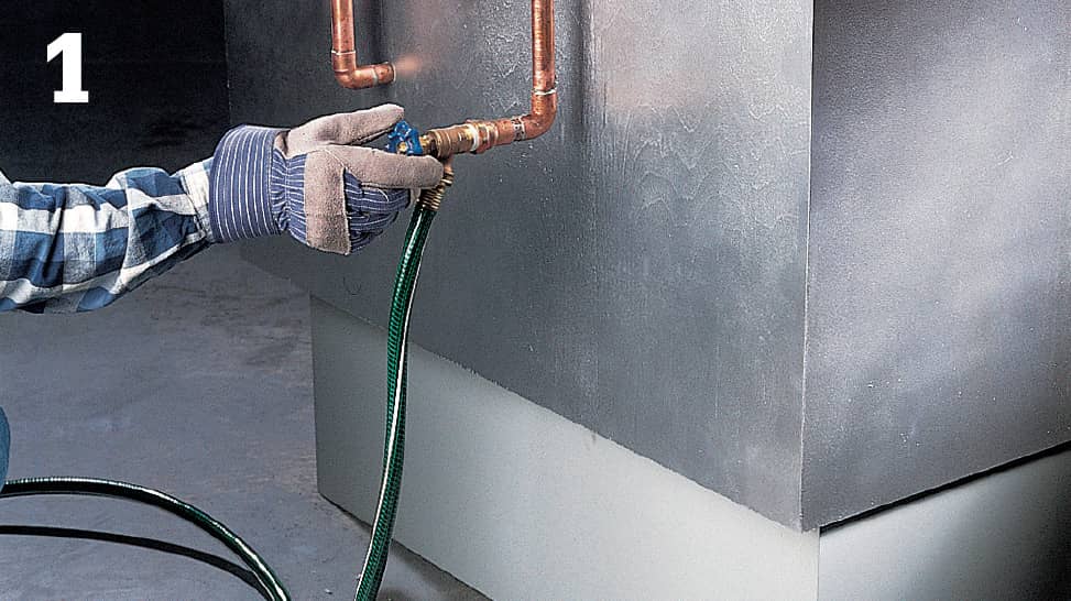
Use a garden hose to drain water from the boiler. Keep the drain end of the hose lower than the drain cock on the boiler.
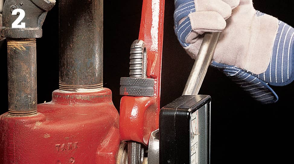
If the valve or gauge on top of the boiler is attached to a separate fitting, hold the fitting still with one wrench while removing the valve or gauge with another.
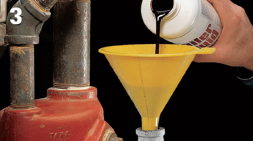
Using a funnel, add a recommended rust inhibitor to the boiler through the valve or gauge fitting.
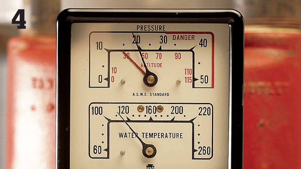
The boiler should reach a pressure of 20 psi before you turn the power back on.
Bleeding a Hot Water System
Hot water systems operate more quietly and efficiently if you bleed them of trapped air once a year. To bleed a hot water system, the boiler must be on. Start with the radiator that’s highest in the house and farthest from the boiler. Place a cloth under the bleed valve, and open the valve slowly (photo 1). Close it as soon as water squirts out. Some bleed valves have knobs, which open with a half turn; others must be opened with a screwdriver or valve key, available at hardware stores.
Steam radiators have automatic bleed valves. To clear a clogged valve, close the shutoff at the radiator and let unit cool. Unscrew the bleed valve and clear the orifice with a fine wire or needle (photo 2).
Older hot water convector systems may have bleed valves on or near the convectors. Bleed these convectors as you would radiators.
Most convector systems today don’t have bleed valves. For these, locate the hose bib where the return water line reaches the boiler. Close the gate valve between the bib and the boiler. Attach a short section of hose to the bib and immerse the other end in a bucket of water. Open the bib while adding water to the boiler by opening the supply valve. The supply valve is located on the supply pipe, usually the smallest pipe in the system. Flush the system until no air bubbles come out of the hose in the bucket (photo 3). Open the gate valve to bleed any remaining air. Close the hose bib before restarting the boiler.
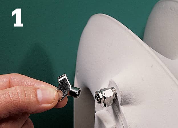
If you can’t find a key for your radiators, a local hardware store or home center may have a replacement.
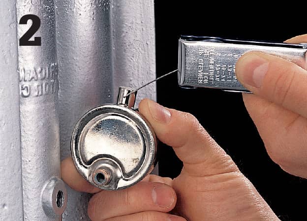
If the radiator isn’t heating, clear the orifice with a fine wire or needle.
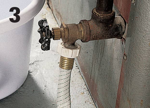
A convector-based heating system is usually bled at the boiler by holding a hose underwater and flushing the system until there are no more air bubbles coming from the hose.
 Identifying & Repairing Exhaust Leaks
Leaks in the exhaust flue, around the burner mounting flange, combustion chamber cover plate, or fire door are potential sources of carbon monoxide. Any leak that might allow carbon monoxide to enter your home should be repaired immediately.
Holes and rusted portions are visible signs of a damaged flue. Smaller leaks can be found by turning on the burner and holding a lighted candle along the joints in the flue and the seams of the burner mounting flange, combustion chamber cover plate, and fire door. The flame is drawn toward the joint or seam when there is a leak.
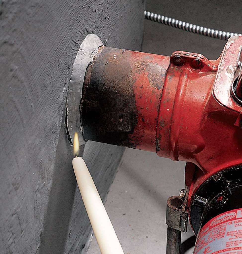
Hold a lighted candle to the joints on the flue and seams around the burner to find leaks.
Sealing an Exhaust Leak
To seal a leak at a seam, turn off the burner and let the boiler cool. Then, use a wire brush to remove any dirt or rust that has accumulated around the leak (photo 1).
Seal the leak by applying refractory furnace cement with a putty knife (photo 2). To stop a mounting flange leak, loosen the retaining bolts located at the edges of the flange. Scrape away the decayed gasket and apply refractory furnace cement at the edge. Then, tighten the bolts.
To test your repair, turn on the boiler and hold a lighted candle to the repair area. The candle flame should not flicker or waver.
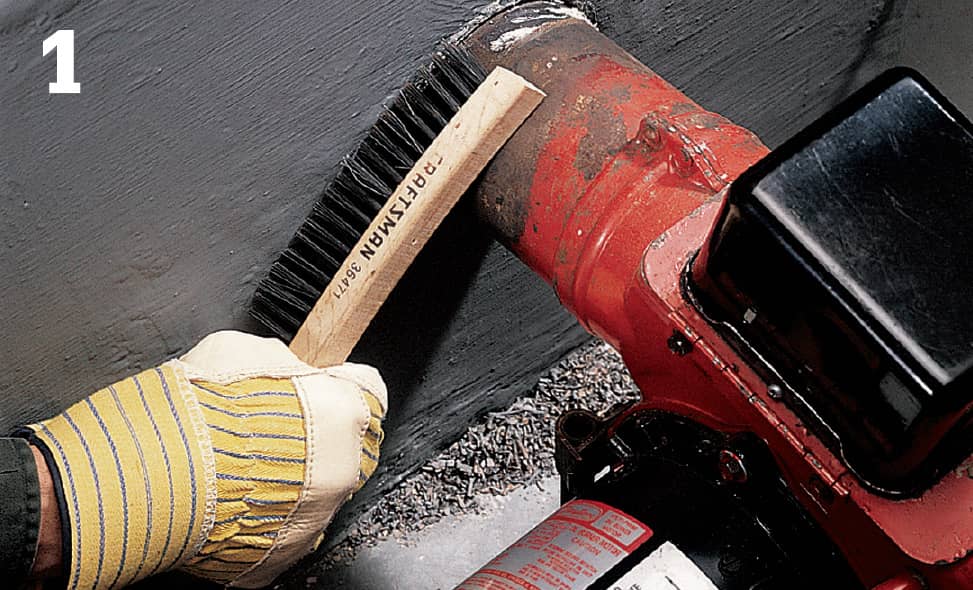
Use a wire brush to clean off any rust or dirt deposits that have accumulated on the surface.
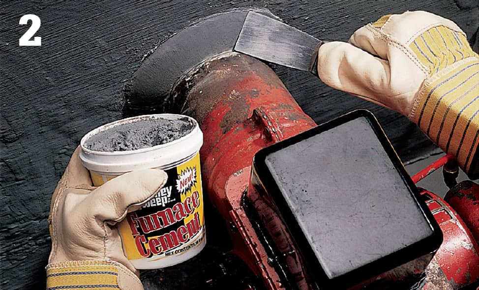
With a putty knife, apply refractory furnace cement to seal the leak.
 Replacing Dishwashers
A dishwasher that’s past its prime may be inefficient in more ways than one. If it’s an old model, it probably wasn’t designed to be very efficient to begin with. But more significantly, if it no longer cleans effectively, you’re probably spending a lot of time and hot water pre-rinsing the dishes. This alone can consume more energy and water than a complete wash cycle on a newer machine. So even if your old dishwasher still runs, replacing it with an efficient new model can be a good green upgrade.
In terms of sizing and utility hookups, dishwashers are generally quite standard. If your old machine is a built-in and your countertops and cabinets are standard sizes, most full-size dishwashers will fit right in. Of course, you should always measure the dimensions of the old unit before shopping for a new one to avoid an unpleasant surprise at installation time. Also be sure to review the manufacturer’s instructions before starting any work.
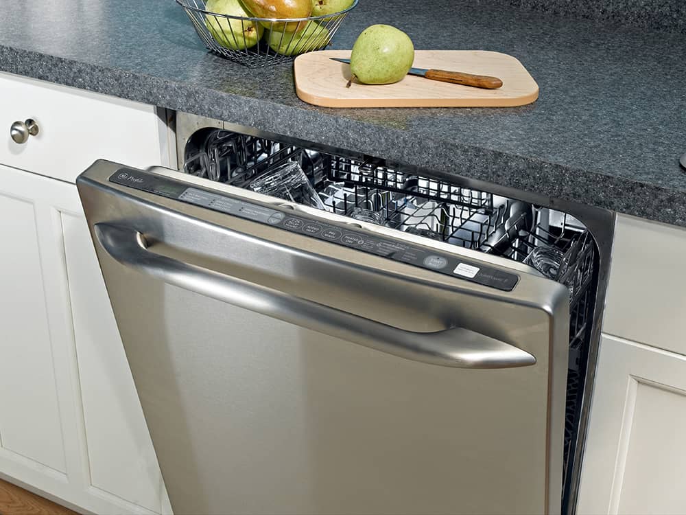
Replacing an old, inefficient dishwasher is a straightforward project that usually takes just a few hours. The energy and water savings start with the first load of dishes and continue with every load thereafter.
How to Replace a Dishwasher
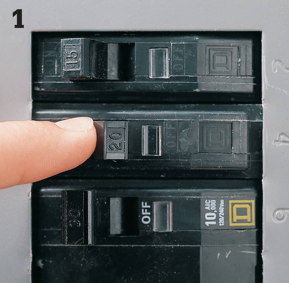
Start by shutting off the electrical power to the circuit at the main service panel. Also, turn off the water supply at the shutoff valve, usually located directly under the floor or in the cabinet beneath the kitchen sink. NOTE: Most local codes now require that dishwashers be on a GFCI-protected circuit. If yours is not, it’s always a good idea to replace the regular receptacle with a GFCI-protected model, or to replace the circuit breaker at the main panel with a GFCI breaker.
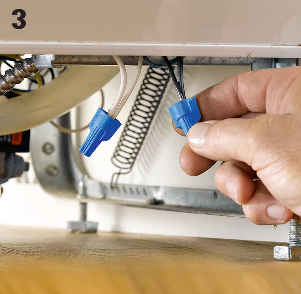
Disconnect old wiring connections. The dishwasher has an integral electrical box at the front of the unit where the power cable is attached to the dishwasher’s fixture wires. Take off the box cover and remove the wire connectors that join the wires together.
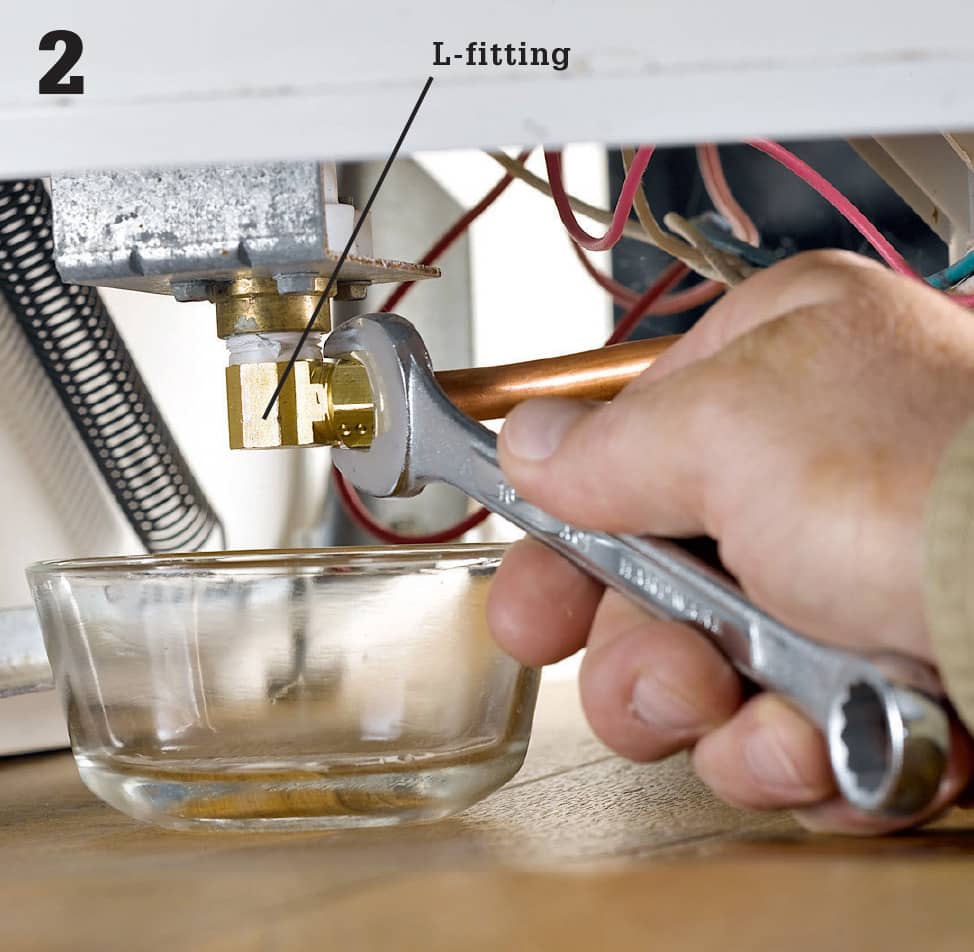
Disconnect old plumbing connections. First unscrew the front access panel. Once the access panel is removed, disconnect the water supply line from the L-fitting on the bottom of the unit. This is usually a brass compression fitting, so just turning the compression nut counterclockwise with an adjustable wrench should do the trick. Use a bowl to catch any water that might leak out when the nut is removed.
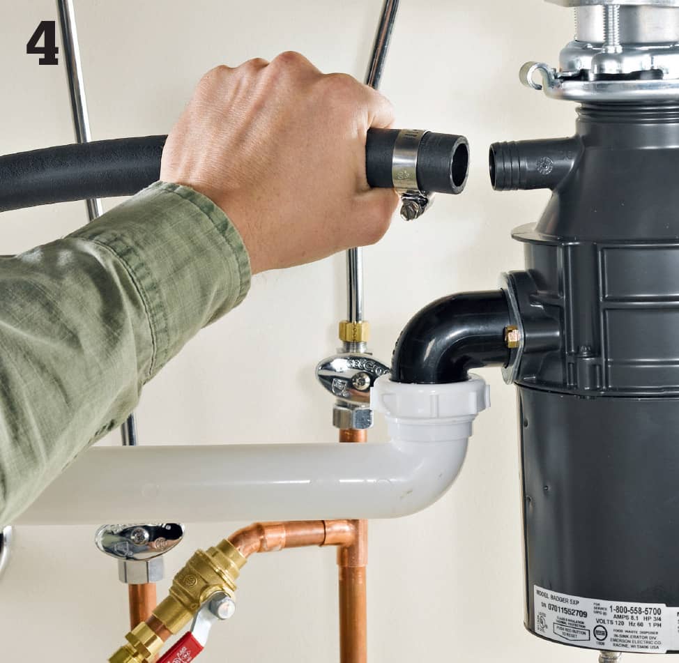
Disconnect the discharge hose, which is usually connected to the dishwasher port on the side of the garbage disposer. To remove it, just loosen the screw on the hose clamp and pull it off. You may need to push this hose back through a hole in the cabinet wall and into the dishwasher compartment so it won’t get caught when you pull the dishwasher out.
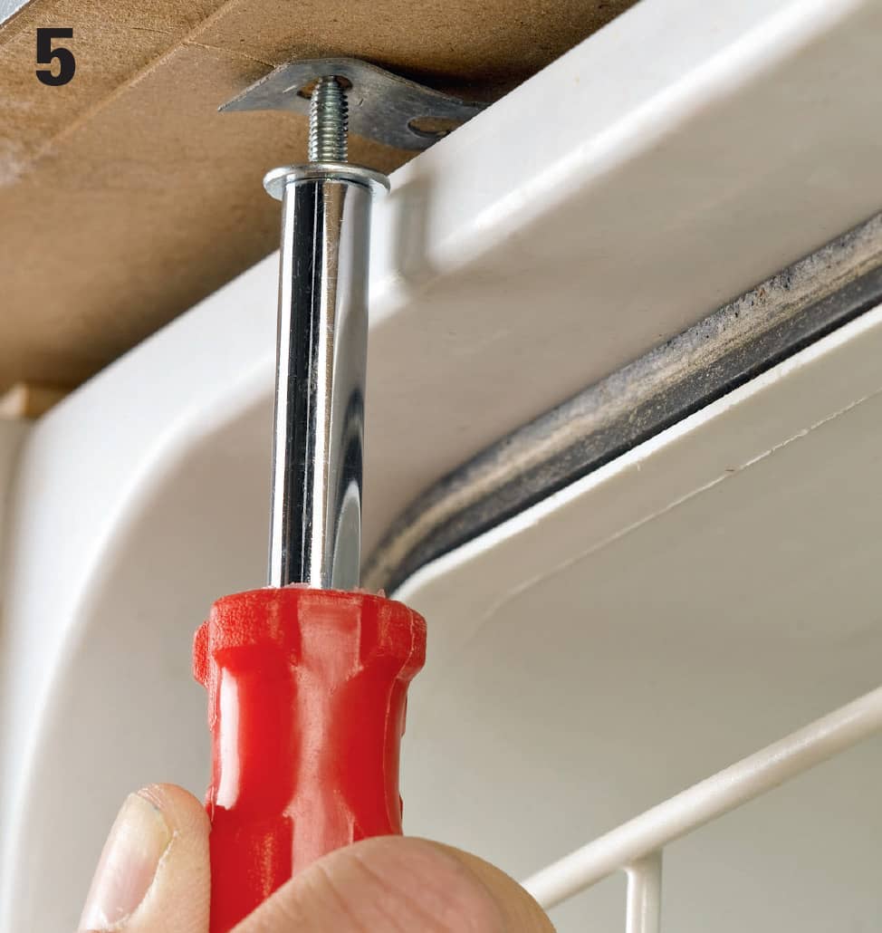
Detach the unit from the cabinets before you pull it out. Remove the screws that hold the brackets to the underside of the countertop. Then put a piece of cardboard or old carpet under the front legs to protect the floor from getting scratched, and pull the dishwasher out.
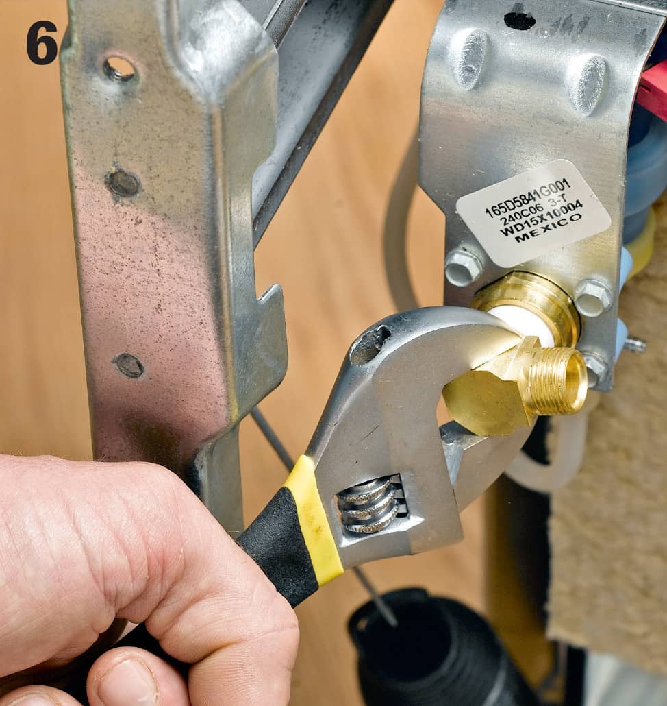
First, read the appliance’s installation instructions carefully and then prepare the new dishwasher to be installed. Tip it on its back and attach the new L-fitting into the threaded port on the solenoid. Apply some Teflon tape to the fitting threads before tightening to allow the coupling to be tightened fully.
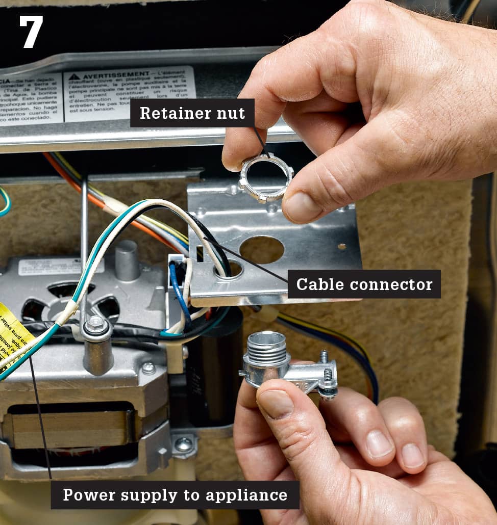
Prepare for the wiring connections. Like the old dishwasher, the new one will have an integral electrical box for making the wiring connections. To gain access to the box, just remove the box cover. Then install a cable connector on the back of the box and bring the power cable from the service panel through this connector. Power should be shut off at the main service panel at all times.
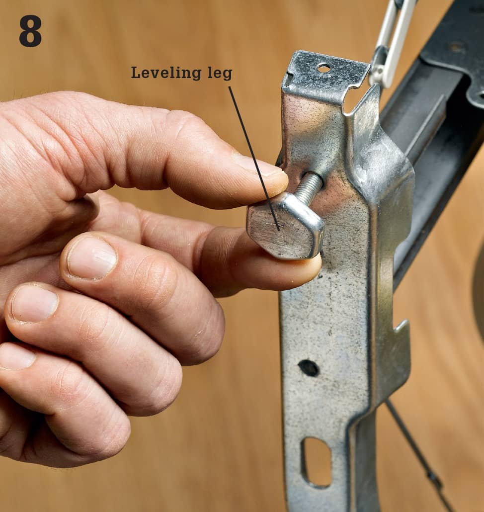
Install a leveling leg at each of the four corners while the new dishwasher is still on its back. Just turn the legs into the threaded holes designed for them. Leave about 1/2" of each leg projecting from the bottom of the unit. These will have to be adjusted later to level the appliance. Tip the appliance up onto the feet and slide it into the opening. Check for level in both directions and adjust the feet as required.
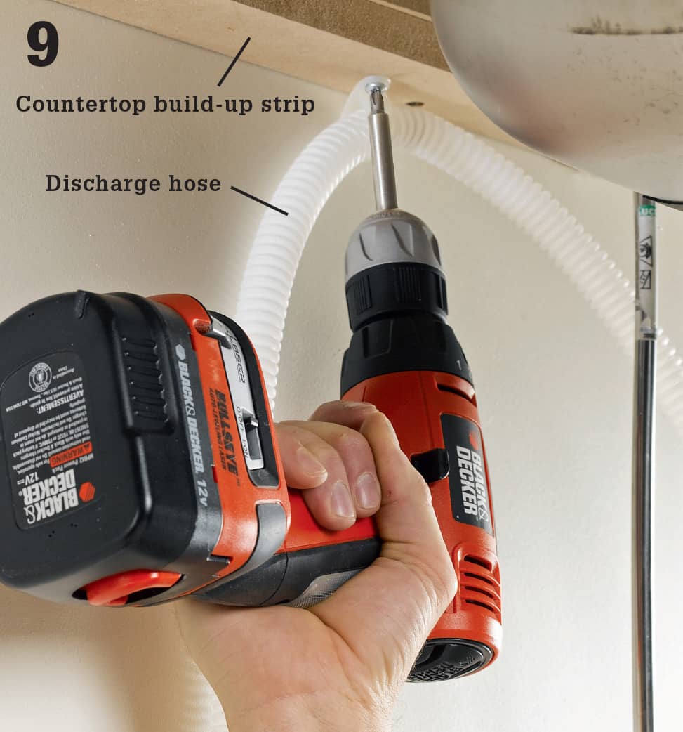
Once the dishwasher is level, attach the brackets to the underside of the countertop to keep the appliance from moving. Then pull the discharge hose into the sink cabinet and install it so there’s a loop that is attached with a bracket to the underside of the countertop. This loop prevents waste water from flowing from the disposer back into the dishwasher. NOTE: Some codes require that you install an air gap fitting for this purpose. Check with your local plumbing inspector.
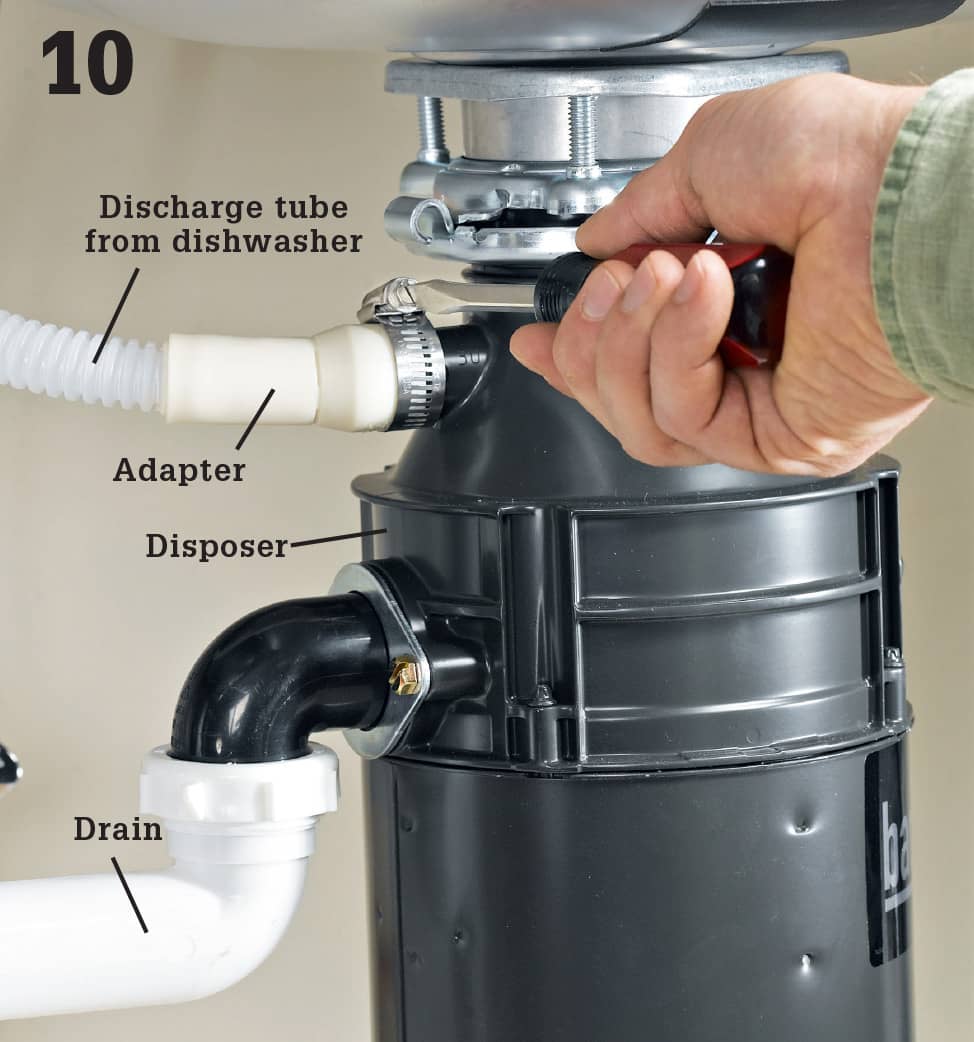
Push an adapter over the disposer’s discharge nipple and tighten it in place with a hose clamp. If you don’t have a disposer, replace one of the drain tailpieces with a dishwasher tailpiece, and clamp the discharge tube to its fitting.
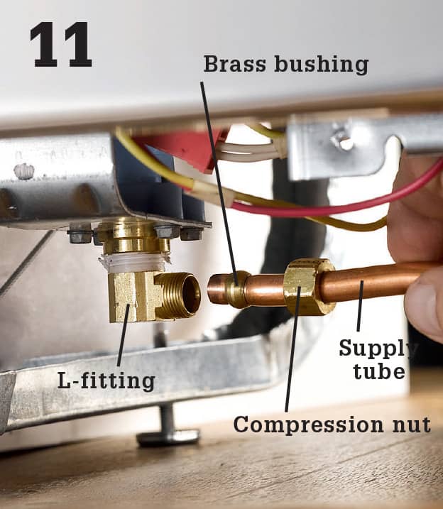
Adjust the L-fitting on the dishwasher’s water inlet valve until it points directly toward the water supply tubing. Then lubricate the threads slightly with a drop of dishwashing liquid and tighten the tubing’s compression nut onto the fitting, keeping the brass bushing between the nut and the L-fitting. Use an adjustable wrench and turn the nut clockwise.
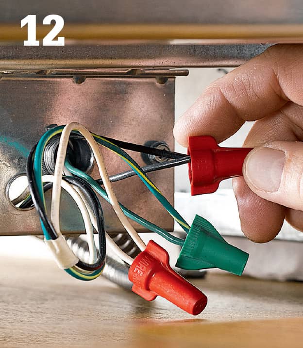
Complete the electrical connections by clamping the cable and joining the wires with wire nuts, following manufacturer’s instructions. Replace the electrical cover, usually by hooking it onto a couple of prongs and driving a screw. Restore power and water, and test. Replace the toe-kick.
 Replacing Food Disposers
Food disposers are standard equipment in the modern home, and most of us have come to depend on them to macerate our plate leavings and crumbs so they can exit the house along with waste water from the sink drain. If your existing disposer needs replacing, you’ll find that the job is relatively simple, especially if you select a replacement appliance that is the same model as the old one. In that case, you can probably reuse the existing mounting assembly, drain sleeve, and drain plumbing.
Disposers are available with power ratings between 1/3 and 1 HP (horsepower). More powerful models bog down less under load and the motors last longer because they don’t have to work as hard. They are also costlier.
Choose a switch option that meets your family’s safety needs. A “continuous feed” disposer may be controlled by a standard on-off switch on the wall. Another option is a disposer that stays on only when the switch is actively pressed. A “batch feed” disposer can turn on only when a lid is locked onto it, eliminating the possibility of harming fingers. Some models are controlled at the lid, without a wall switch. Continuous food disposers are the most common.
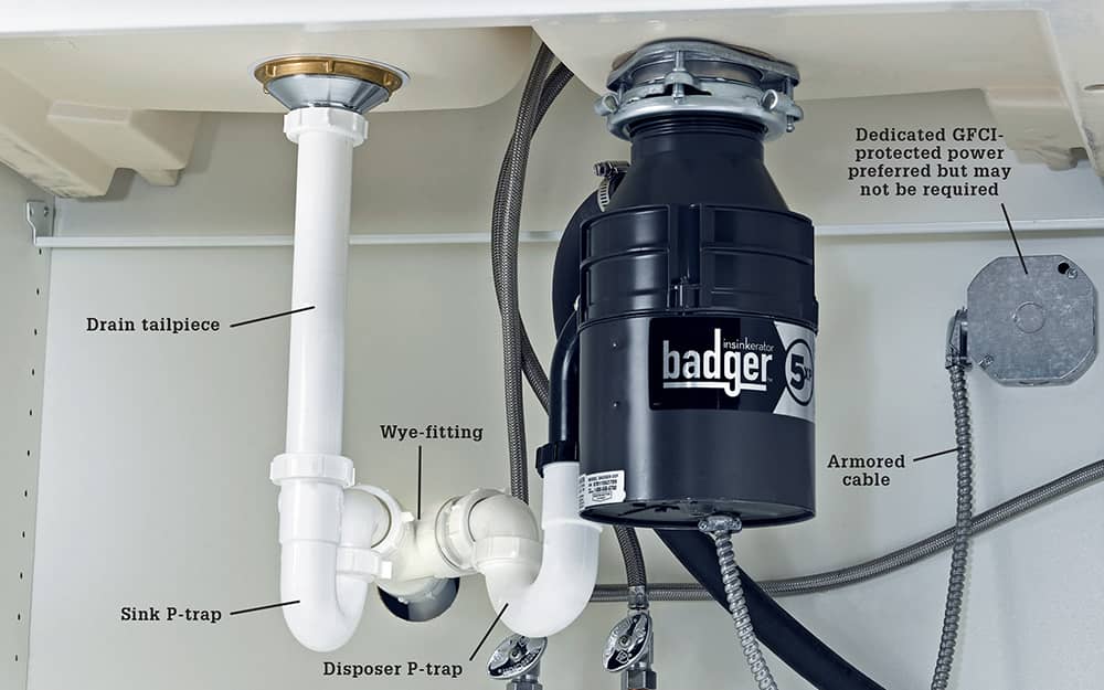
A properly functioning food disposer that’s used correctly can help reduce clogs. Some plumbers use separate P-traps for the disposer and the drain outlet tube as shown here. Others contend that configuring the drain line with a single P-trap minimizes the chance that a trap will have its water seal broken by suction from the second trap. See page 519, lower left.
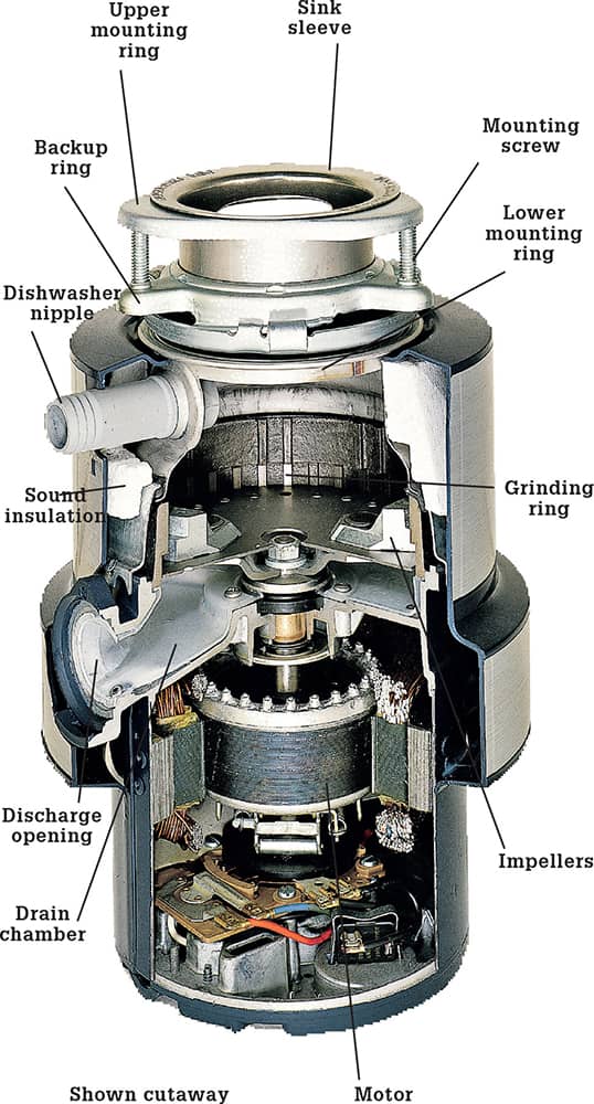
A food disposer grinds food waste so it can be flushed away through the sink drain system. A quality disposer has a 1/2–horsepower, or larger, self-reversing motor. Other features to look for include foam sound insulation, a grinding ring, and overload protection that allows the motor to be reset if it overheats. Better food disposers have a 5-year manufacturer’s warranty.
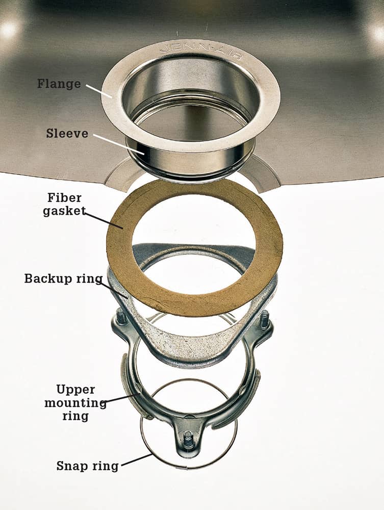
The disposer is attached directly to the sink sleeve, which comes with the disposer and replaces the standard sink strainer. A snap ring fits into a groove around the sleeve of the strainer body to prevent the upper mounting ring and backup ring from sliding down while the upper mounting ring is tightened against the backup ring with mounting screws. Use a fiber gasket compressor when the mounting screws are tightened to create a better seal under the flange.
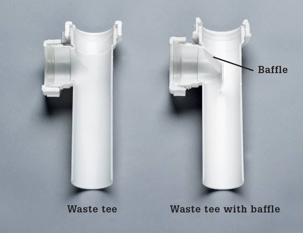
Kitchen and drain tees are required to have a baffle if the tee is connected to a dishwasher or disposer. The baffle is intended to prevent discharge from finding its way up the drain and into the sink.
How to Replace a Food Disposer
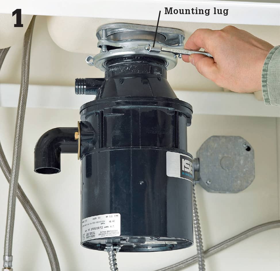
Remove the old disposer if you have one. You’ll need to disconnect the drain pipes and traps first. If your old disposer has a special wrench for the mounting lugs, use it to loosen the lugs. Otherwise, use a screwdriver. If you do not have a helper, place a solid object directly beneath the disposer to support it before you begin removal. IMPORTANT: Shut off electrical power at the main service panel before you begin removal. Disconnect the wire leads, cap them, and stuff them into the electrical box.
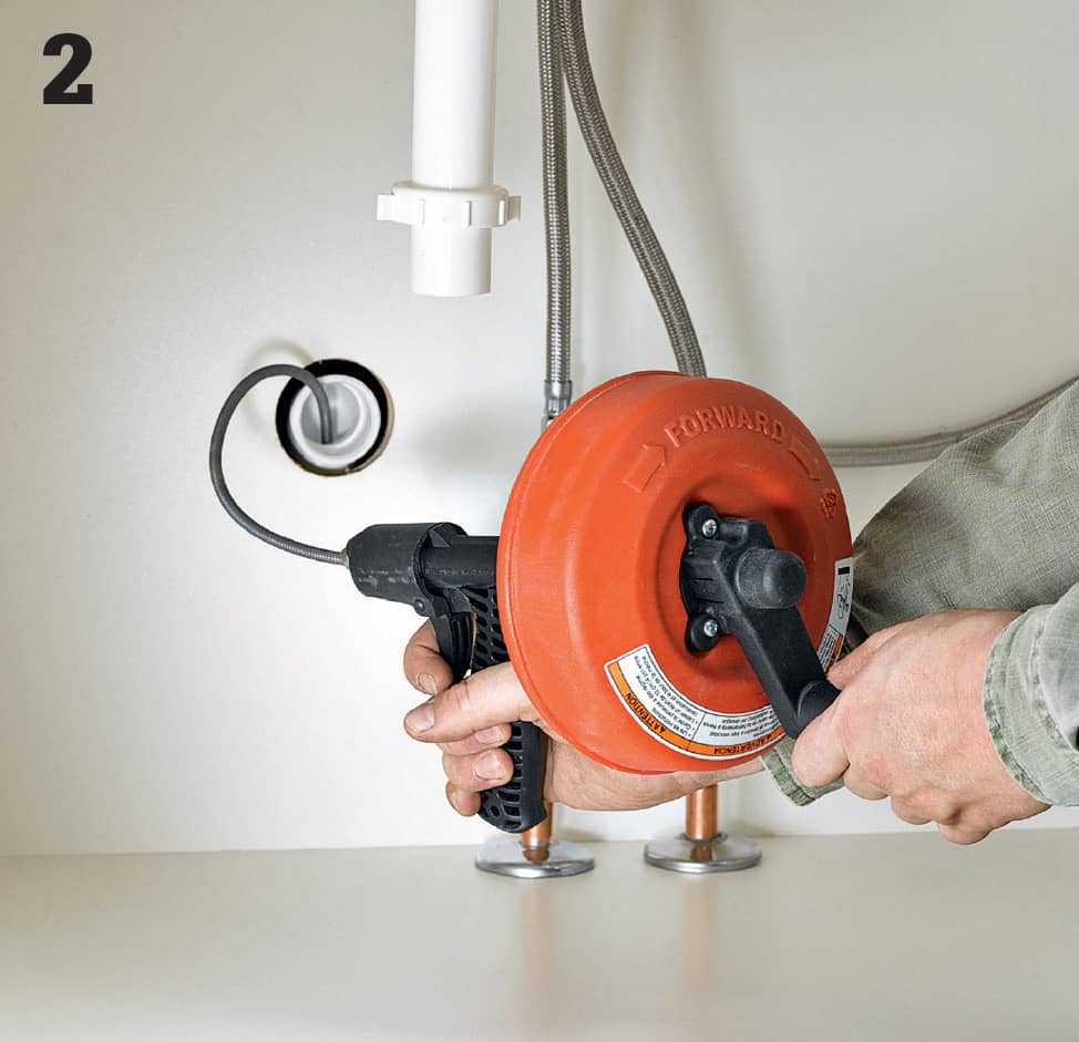
Clear the drain lines all the way to the branch drain before you begin the new installation. Remove the trap and trap arm first.
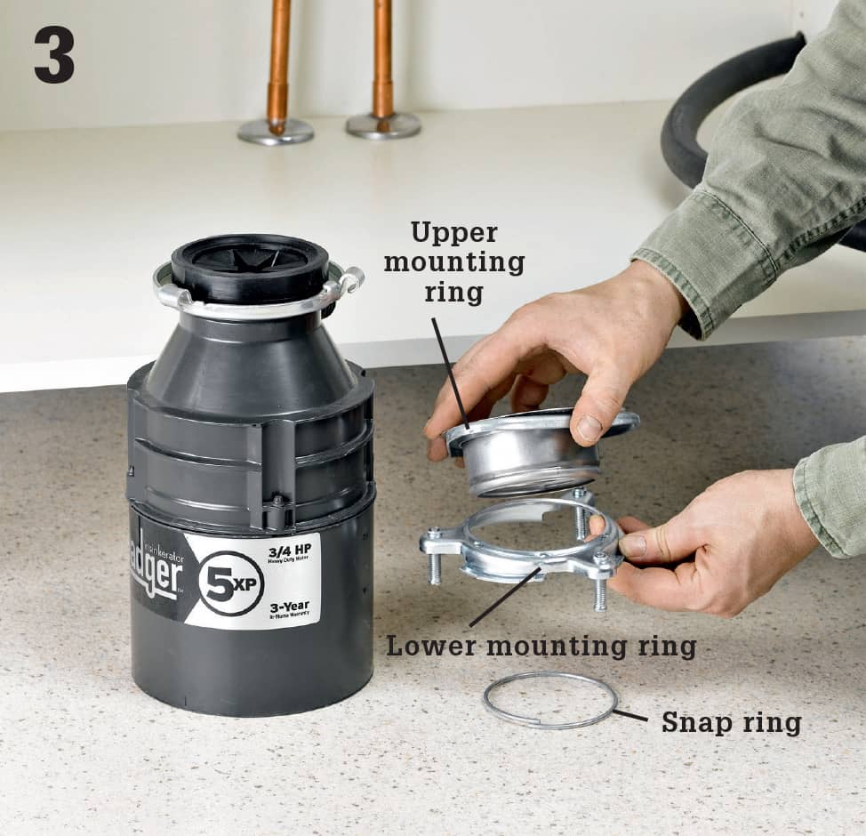
Disassemble the mounting assembly and then separate the upper and lower mounting rings and the backup ring. Also remove the snap ring from the sink sleeve. See photo, previous page.
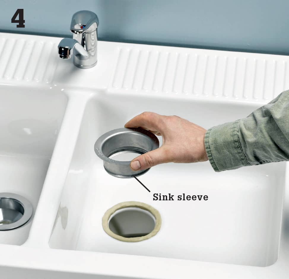
Press the flange of the sink sleeve for your new disposer into a thin coil of plumber’s putty that you have laid around the perimeter of the drain opening. The sleeve should be well-seated in the coil.
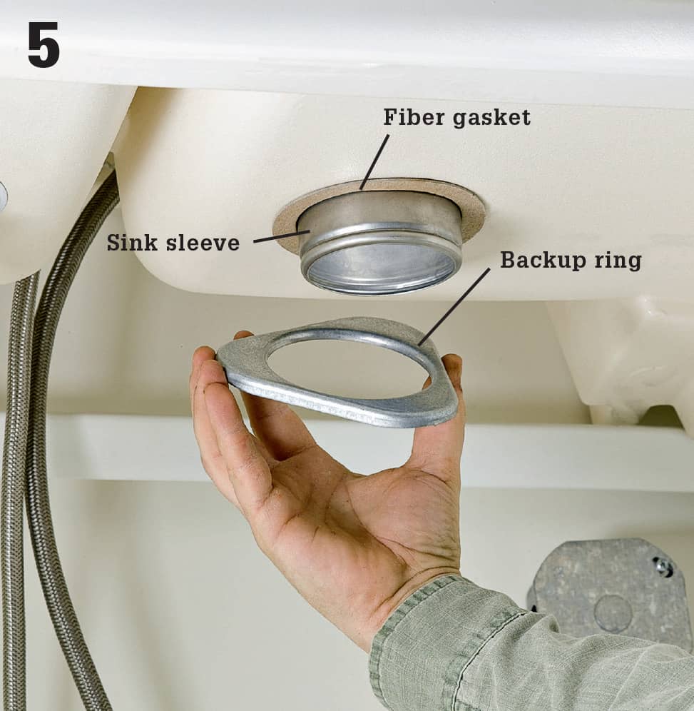
Slip the fiber gasket and then the backup ring onto the sink sleeve, working from inside the sink base cabinet. Make sure the backup ring is oriented the same way it was before you disassembled the mounting assembly.
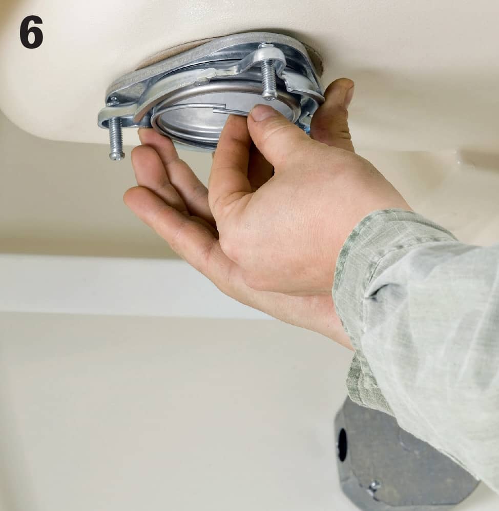
Insert the upper mounting ring onto the sleeve with the slotted ends of the screws facing away from the backup ring so you can access them. Then, holding all three parts at the top of the sleeve, slide the snap ring onto the sleeve until it snaps into the groove.
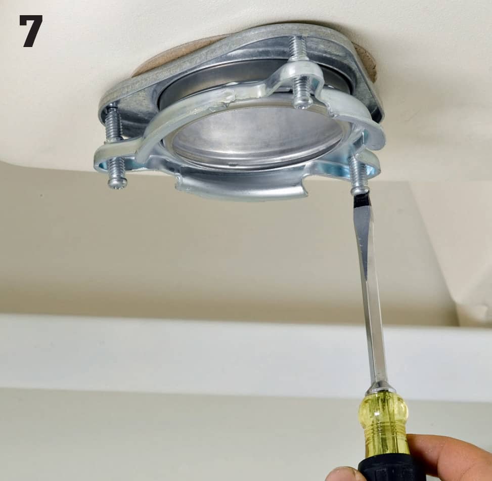
Tighten the three mounting screws on the upper mounting ring until the tips press firmly against the backup ring. It is the tension created by these screws that keeps the disposer steady and minimizes vibrating.
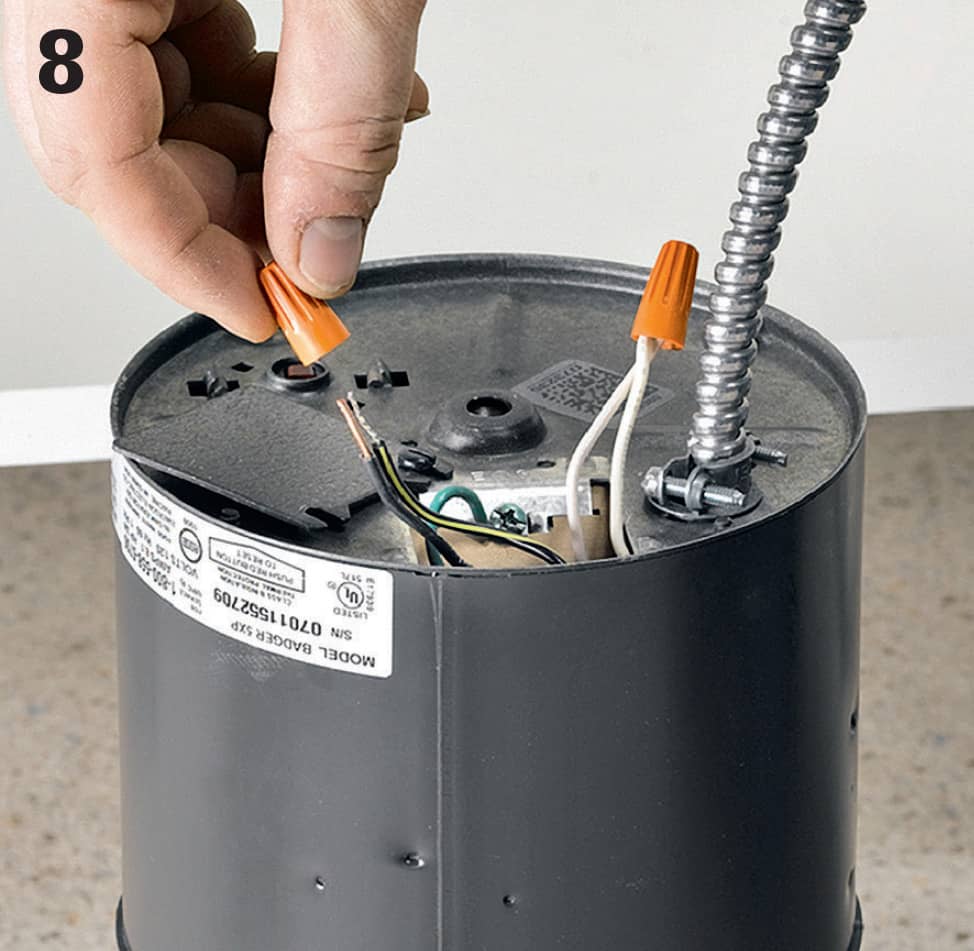
Make electrical connections before you mount the disposer unit on the mounting assembly. Shut off the power at the service panel if you have turned it back on. Remove the access plate from the disposer. Attach the white and black branch circuit wires from the electrical box to the white and black wires (respectively) inside the disposer. Twist a small wire cap onto each connection and wrap it with electrical tape for good measure. Also attach the green ground wire from the box to the grounding terminal on your disposer.
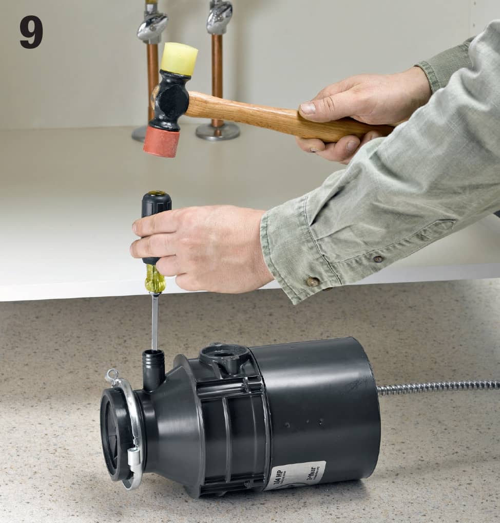
Knock out the plug in the disposer port if you will be connecting your dishwasher to the disposer. If you have no dishwasher, leave the plug in. Insert a large flathead screwdriver into the port opening and rap it with a mallet. Retrieve the knock-out plug from inside the disposer canister.
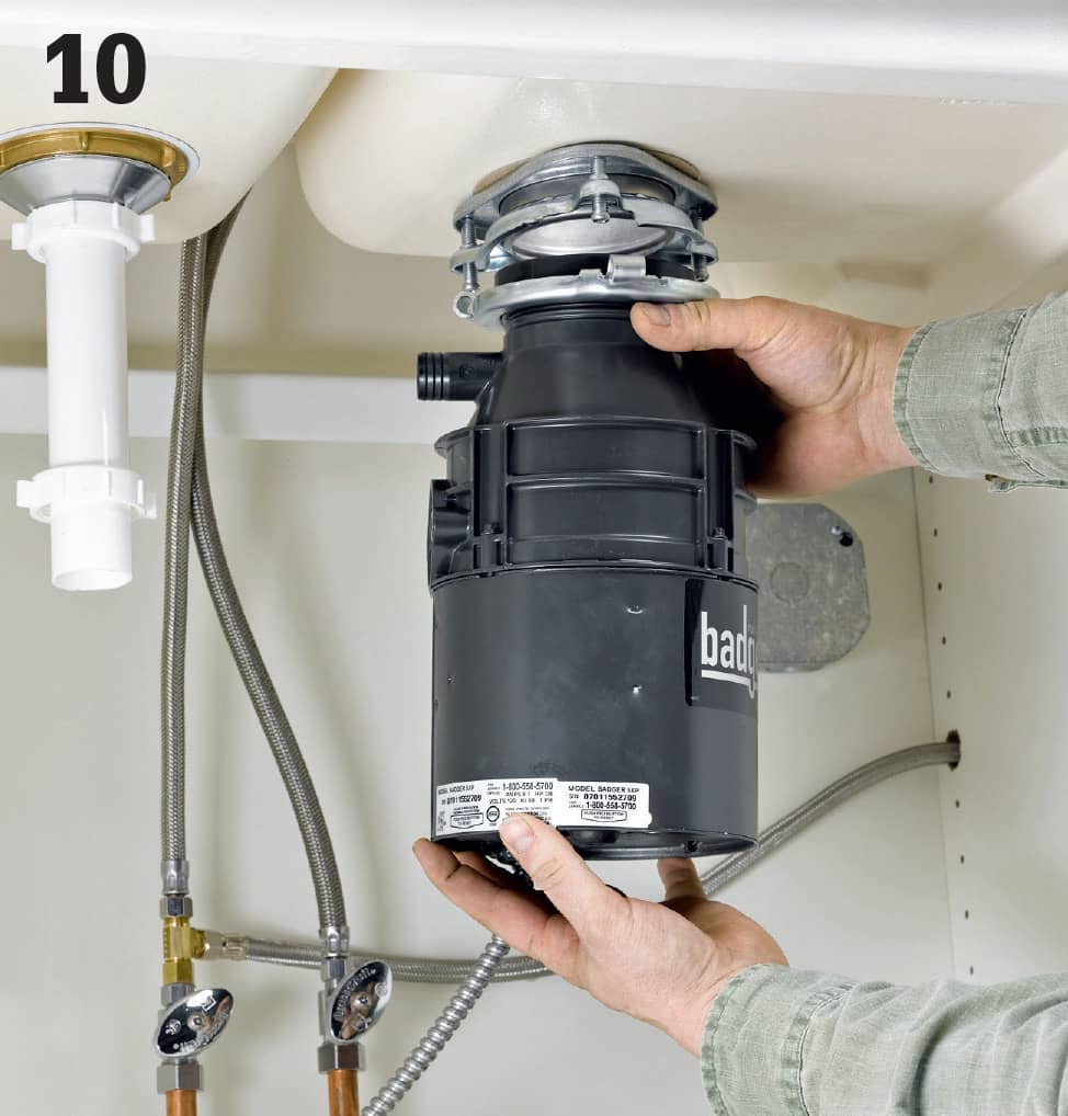
Hang the disposer from the mounting ring attached to the sink sleeve. To hang it, simply lift it up and position the unit so the three mounting ears are underneath the three mounting screws and then spin the unit so all three ears fit into the mounting assembly. Wait until after the plumbing hookups have been made to lock the unit in place.
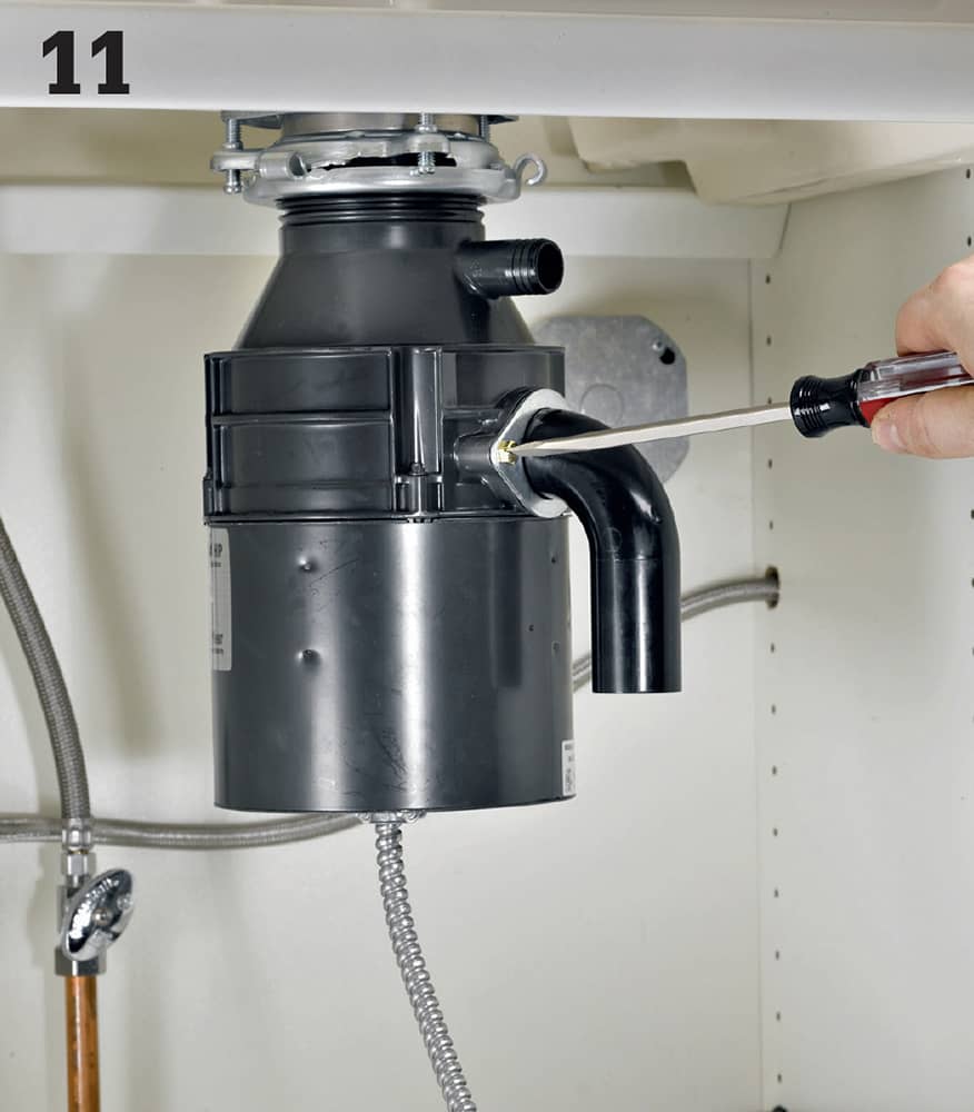
Attach the discharge tube to the disposer according to the manufacturer’s instructions. It is important to get a very good seal here, or the disposer will leak. Go ahead and spin the disposer if it helps you access the discharge port.
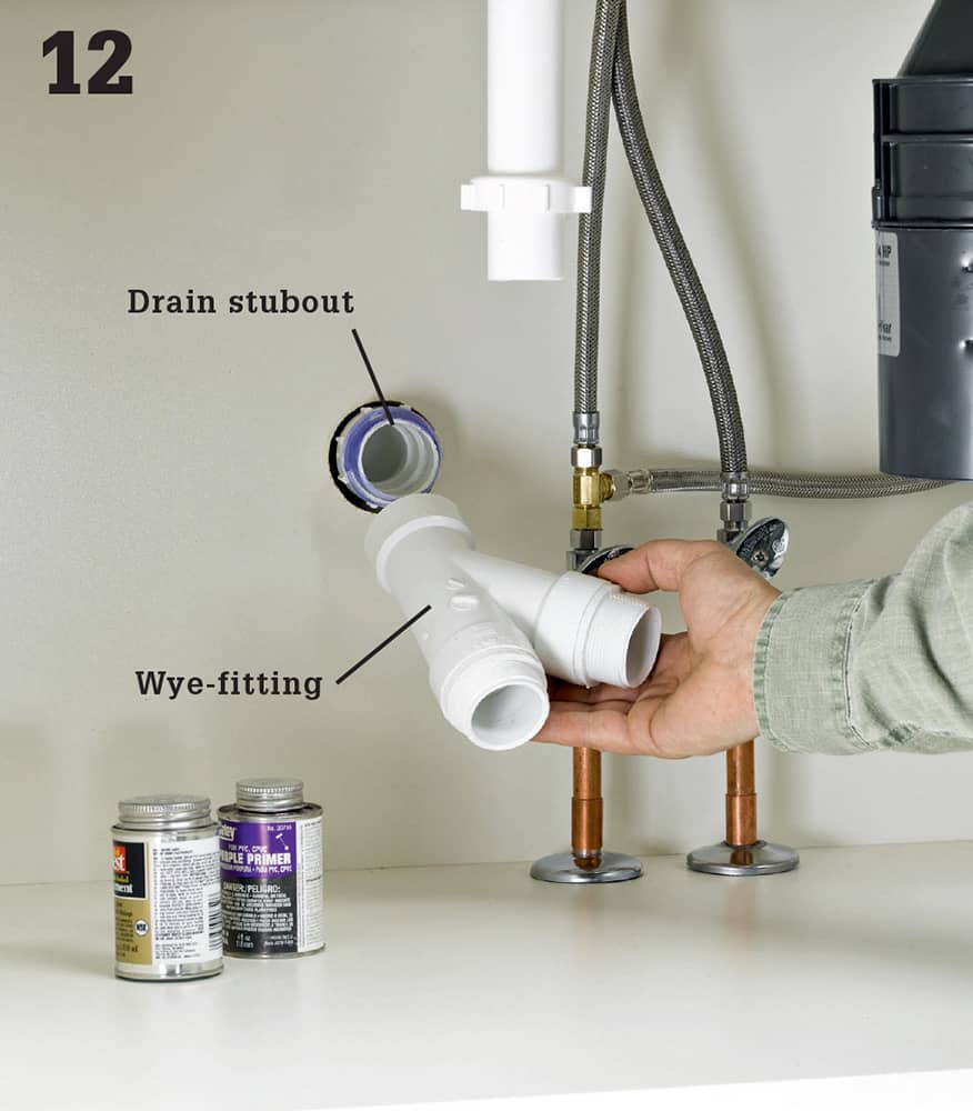
Attach a Wye-fitting at the drain stubout. The Wye-fitting should be sized to accept a drain line from the disposer and another from the sink. Adjust the sink drain plumbing as needed to get from the sink P-trap to one opening of the Wye.
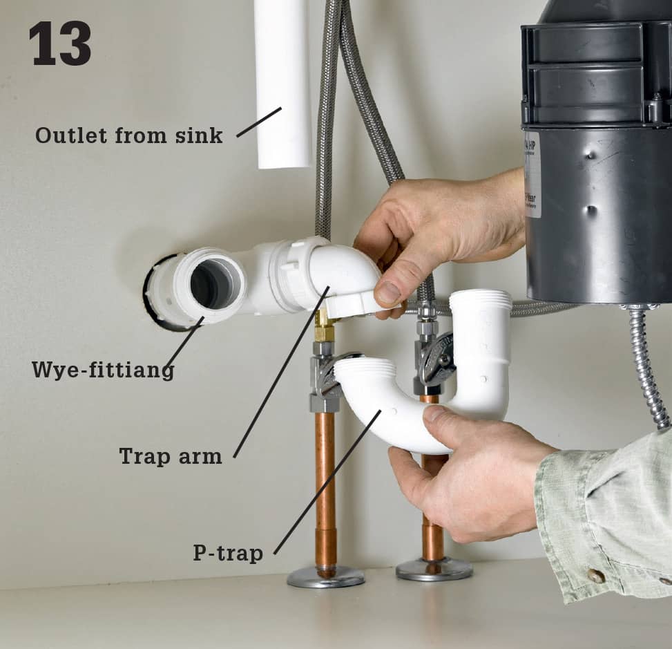
Install a trap arm for the disposer in the open port of the Wye-fitting at the wall stubout. Then, attach a P-trap or a combination of a tube extension and a P-trap so the trap will align with the bottom of the disposer discharge tube.
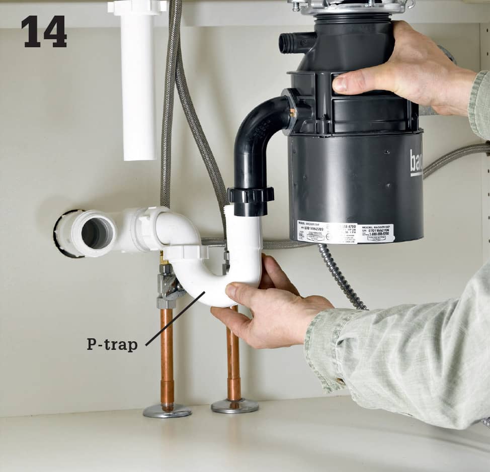
Spin the disposer so the end of the discharge tube is lined up over the open end of the P-trap and confirm that they will fit together correctly. If the discharge tube extends down too far, mark a line on it at the top of the P-trap and cut at the line with a hacksaw. If the tube is too short, attach an extension with a slip joint. You may need to further shorten the discharge tube first to create enough room for the slip joint on the extension. Slide a slip nut and beveled compression washer onto the discharge tube and attach the tube to the P-trap.
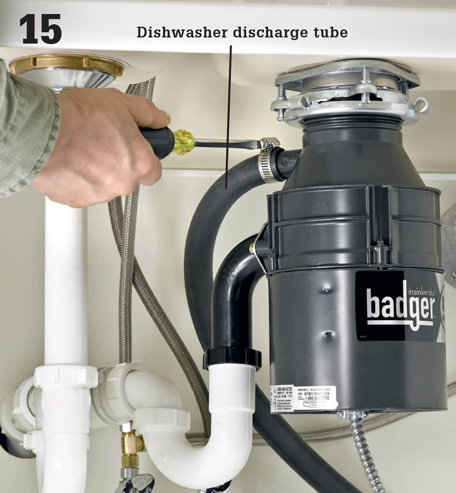
Connect the dishwasher discharge tube to the inlet port located at the top of the disposer unit. This may require a dishwasher hookup kit. Typically, a hose clamp is used to secure the connection.
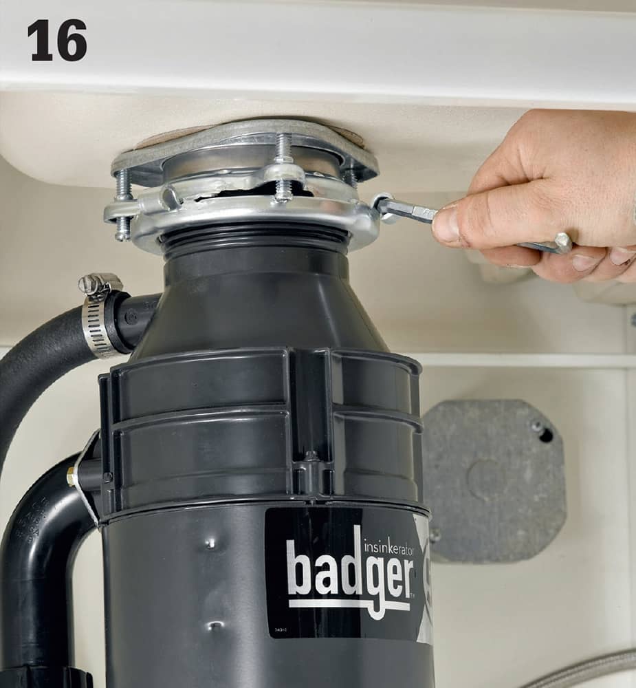
Lock the disposer into position on the mounting ring assembly once you have tested to make sure it is functioning correctly and without leaks. Lock it by turning one of the mounting lugs until it makes contact with the locking notch.
 Replacing Water Heaters
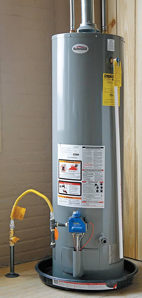
Water heaters typically last for at least 10 years, but once they start to show signs of aging, it’s a good idea to replace them with a new, more efficient appliance.
Replacing a water heater is a relatively easy DIY plumbing task, as long as it is a like-for-like replacement. In an ideal situation, you’d replace the old unit with one of the exact same size and make, and thereby avoid having to move any gas, water, or electrical lines. But if you choose to upgrade or downgrade in size, you’ll find that relocating the necessary lines isn’t that difficult. Although you can usually realize some energy cost savings in the long run, be aware that replacing an electric water heater with a gas-fueled model requires installing a vent and an approved combustion air source (and usually a permit).
It is a commonly held belief that a water heater should last around 10 years. The longevity depends on many factors, including initial quality, usage levels, maintenance diligence, and other miscellaneous factors such as hardness of water. While it is everyone’s goal to get as much use out of our major appliances as possible, it is also undeniable that the best time to replace a water heater is before it leaks and fills your basement with water. It’s a bit of a gamble, but once your old heater starts showing signs of wear and perhaps even acting up a bit, go ahead and make the change.
Water heaters for primary duty in residences range in size from 30 gallons to 65 gallons. For a family of four, a 40- or 50-gallon model should be adequate. While you don’t want to run out of hot water every morning, you also don’t want to pay to heat more water than you use. Base your choice on how well your current water heater is meeting your demand.
Follow local codes when choosing the pipe and fittings for both gas and water. Make sure there is a gas shutoff within 5 feet of the water heater. Also, there should be a union between the shutoff and the water heater, so pipes can be easily dismantled for service.
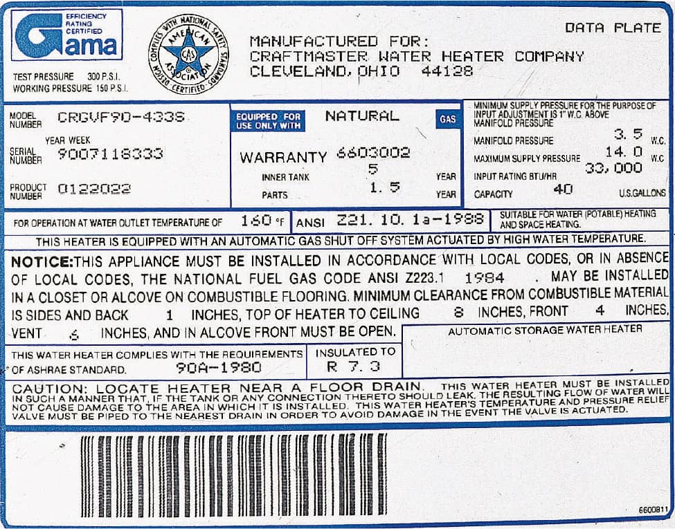
The nameplate on the side of a water heater lists tank capacity, insulation R-value, and working pressure (pounds per square inch). More efficient water heaters have an insulation R-value of 7 or higher. The nameplate for an electric water heater includes the voltage and the wattage capacity of the heating elements and thermostats. Water heaters also have a yellow energy guide label that lists typical yearly operating costs.
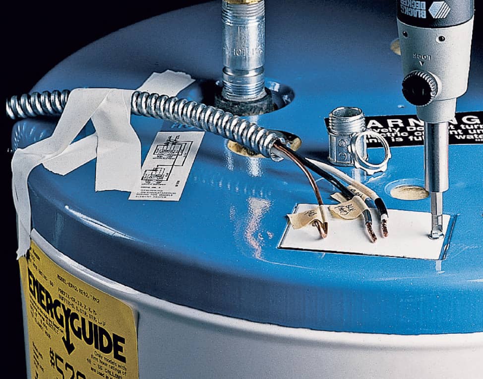
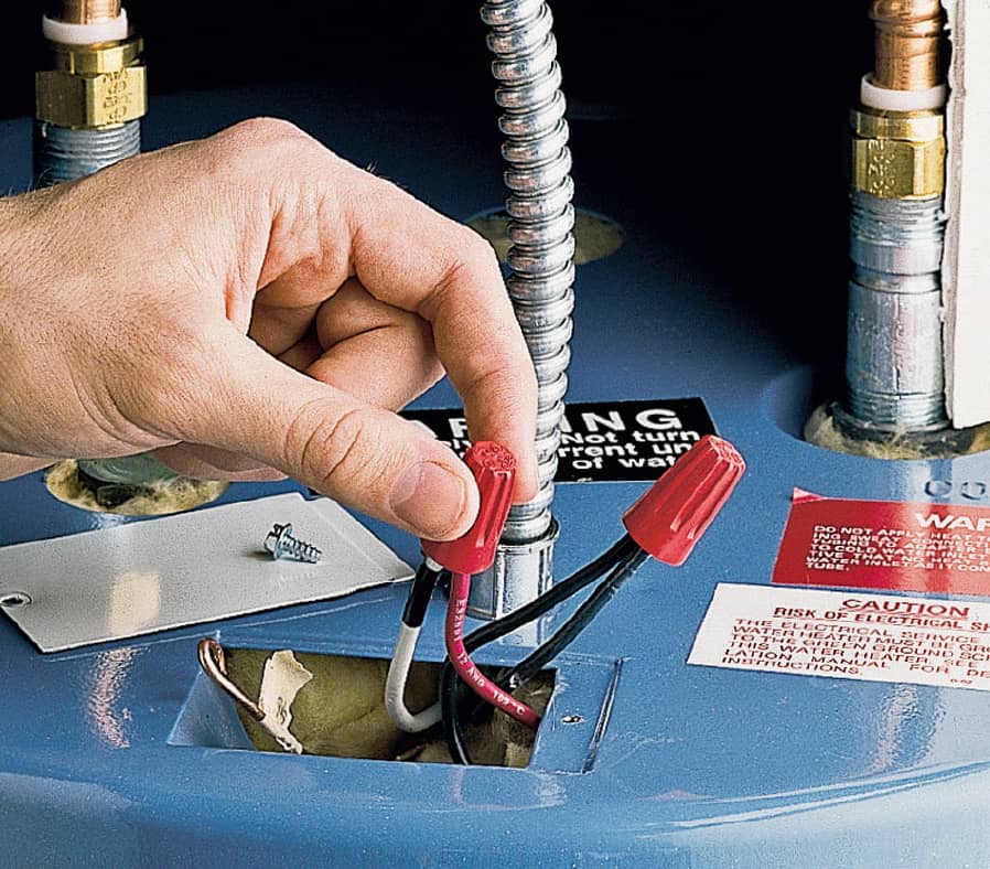
Use armored cable or wires housed in metal conduit to bring electrical power to electric water heaters. The armored cable or conduit should enter the top of the unit through a conduit clamp.
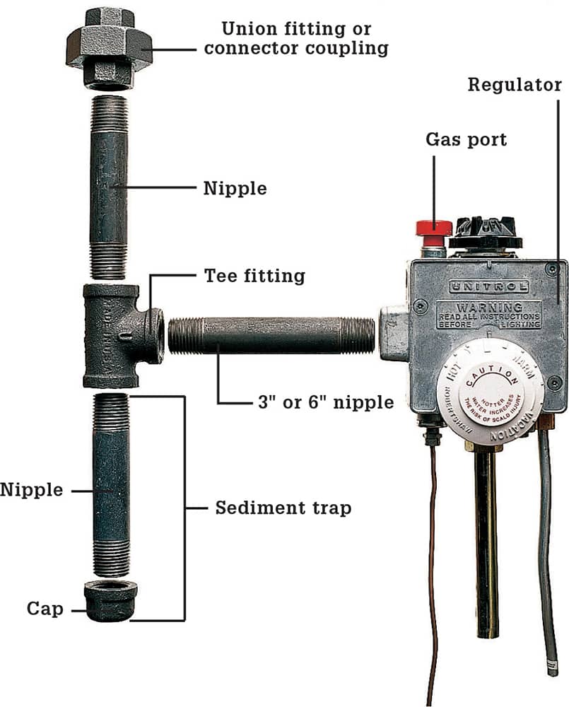
Install a sediment trap between the gascock and the gas port on your gas water heater. A sediment trap is simply a vertical pipe nipple that is installed at the base of the union to allow any impurities in the fuel to collect rather than being drawn into the combustion chamber through the port. In most cases it is easier to locate the sediment trap at the water heater connection point, not the gascock fitting on the supply pipe.
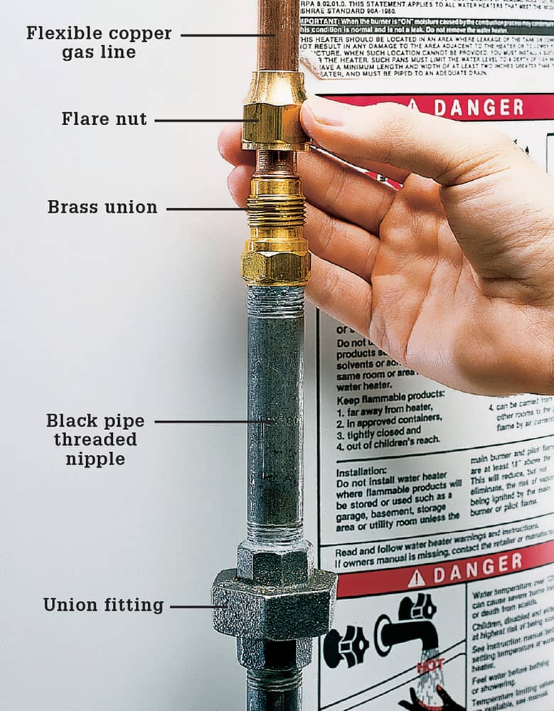
If your house has soft copper gas supply lines, use a flare fitting to connect an additional threaded nipple from the black pipe assembly that connects to the water heater regulator. If you have black pipe supply lines, use a union fitting.
GAS WATER HEATER
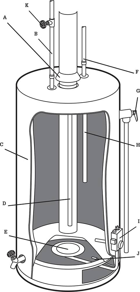
Gas water heater parts include:
(A) Draft hood and vent
(B) Cold water inlet pipe
(C) Tank
(D) Dip tube
(E) Gas burner
(F) Hot water outlet
(G) Temperature/pressure relief valve
(H) Anode rod
(I) Thermostat
(J) Thermocouple
(K) Cold water inlet valve
Gas water heaters operate on either propane or natural gas and are generally very economical to run. They do cost a bit more than electric heaters up front. The following installation features a gas water heater. Check with your local building department to find out if homeowners are allowed to install gas appliances in your municipality.
ELECTRIC WATER HEATER
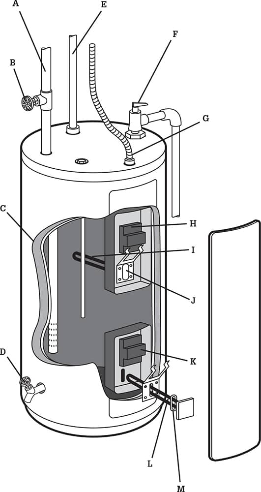
Electric water heater parts can include:
(A) Cold water inlet pipe
(B) Cold water inlet valve
(C) Insulation
(D) Draincock
(E) Hot water outlet pipe
(F) Temperature/pressure relief valve
(G) Power cable
(H) Upper heating element thermostat
(I) Upper heating element
(J) Bracket
(K) Lower heating thermostat
(L) Lower heating element
(M) Gasket
Electric water heaters require 240-volt service, which might overload your service panel if you are replacing a gas heater with an electric model. Their primary advantage is that they are cheaper to purchase (but not to operate) and they do not require that you make gas connections.
How to Remove a Water Heater
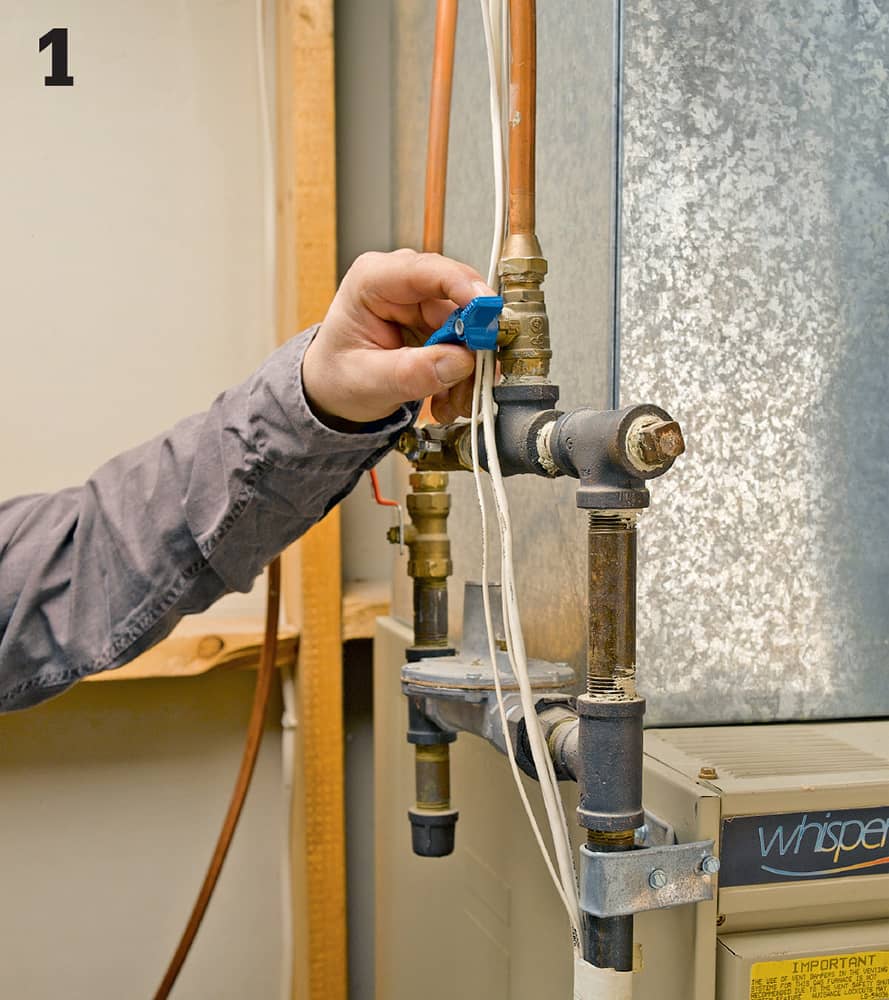
Shut off the gas supply at the stopcock installed in the gas line closest to the water heater. The handle of the stopcock should be perpendicular to the gas supply pipe. Also shut off the water supply.
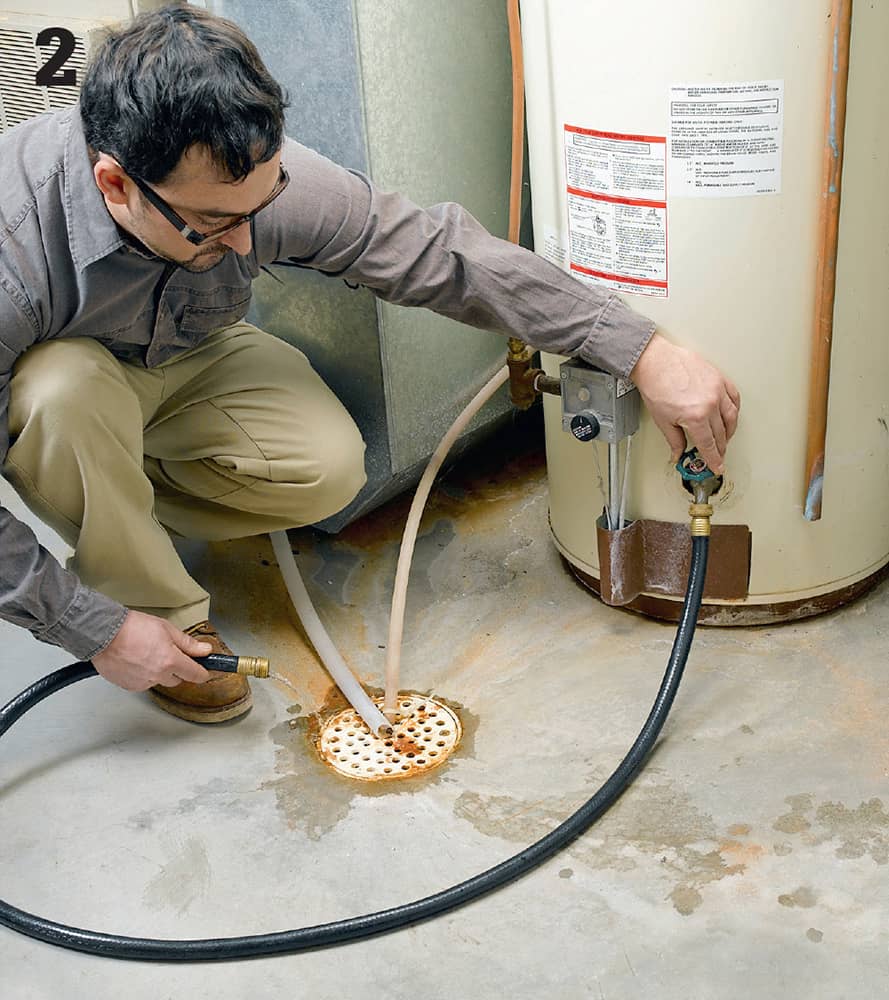
Drain the water from the old heater by hooking a garden hose up to the sillcock drain and running it to a floor drain. If you don’t have a floor drain, drain the water into buckets. For your personal safety, wait until the water heater has been shut off for a couple of hours before draining it.
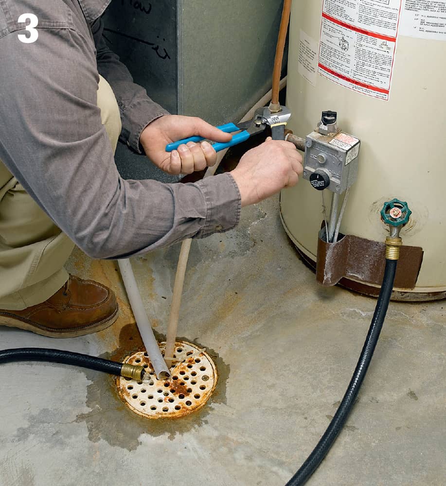
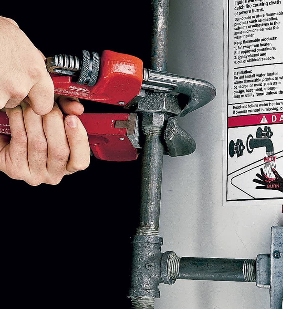
Disconnect the gas supply from the water heater. To do so, loosen the flare fitting with two wrenches or pliers in a soft copper supply line or loosen the union fitting with two pipe wrenches for black pipe supply lines (photo below).
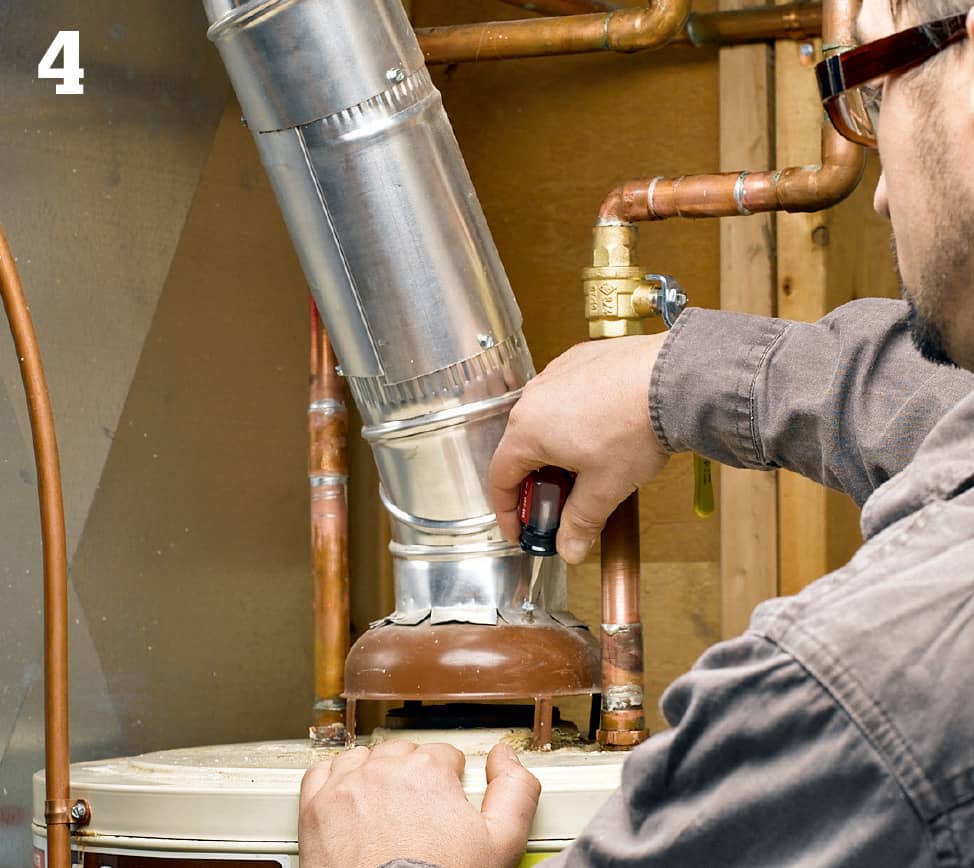
Disconnect the vent pipe from the draft hood by withdrawing the sheet metal screws connecting the parts. Also remove vent pipes up to and including the elbow so you may inspect them for corrosion buildup and replace if needed.
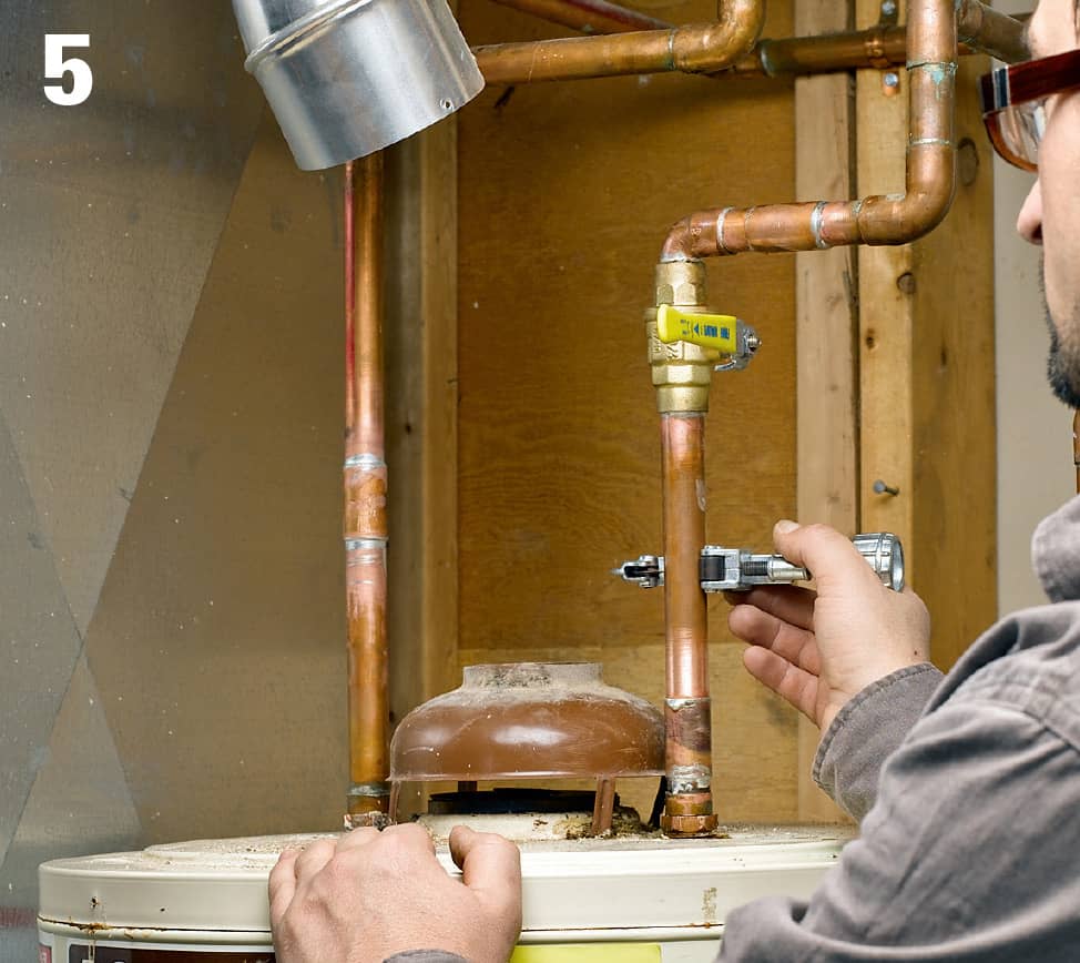
Cut the water supply lines. Prior to cutting, shut off the cold water supply either at the stop valve downline from the heater or at the water meter. Replace the shutoff valve with a new ball-type shutoff valve.
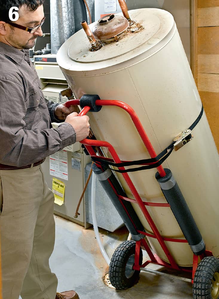
Remove the old water heater and dispose of it properly. Most trash collection companies will haul it away for $20 or $30. Don’t simply leave it out at the curb unless you know that is allowed by your municipal waste collection department. A two-wheel truck or appliance dolly is a big help here. Water heaters usually weigh around 150 pounds.
How to Install a Gas Water Heater
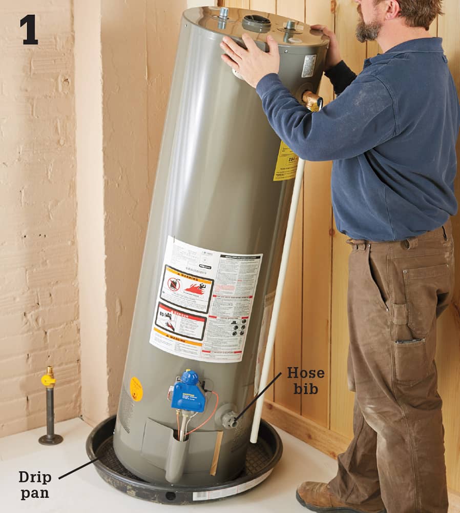
Remove the old unit (see previous pages) and position the new unit in the installation area. A drip pan is required if the water heater is installed where a leak could cause damage. This usually means anywhere except a crawlspace or an unfinished basement. If the water heater is not level, level it by shimming under the bottom with a metal or composite shim.
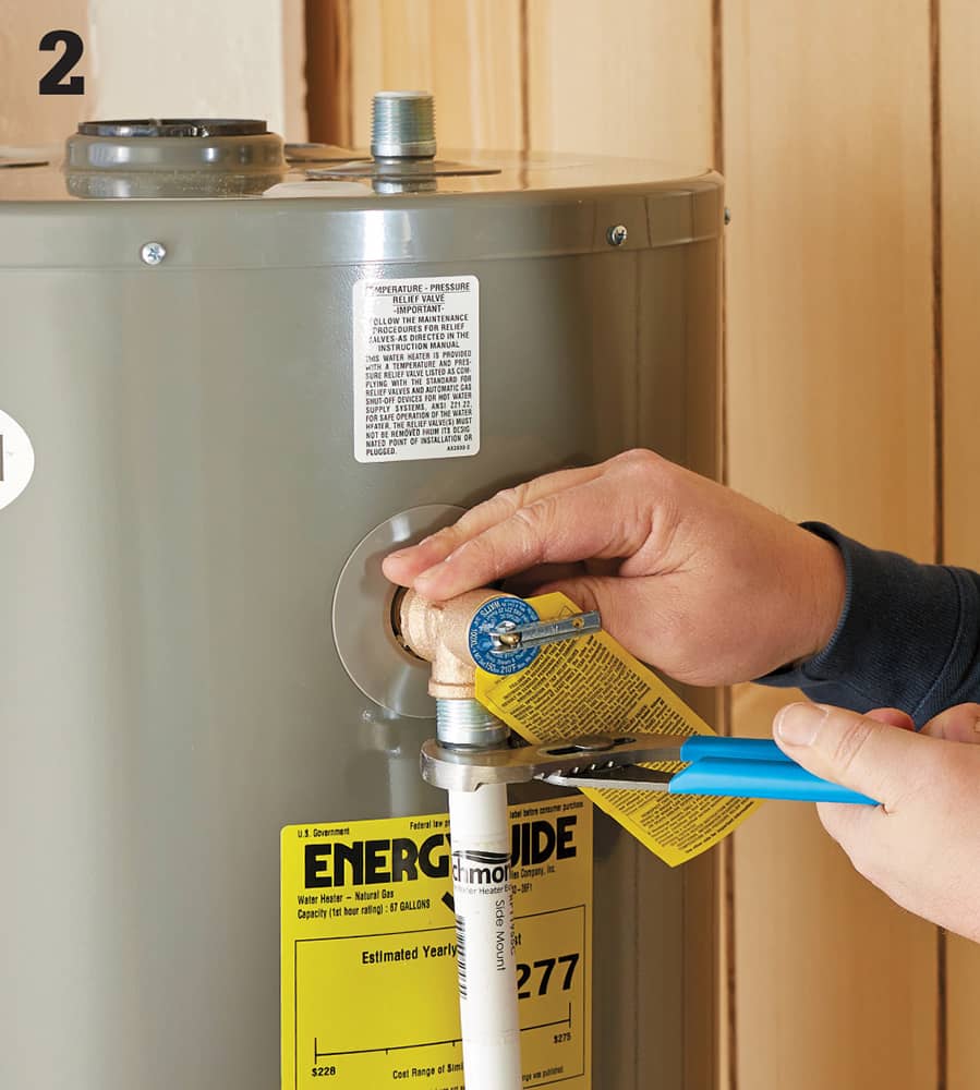
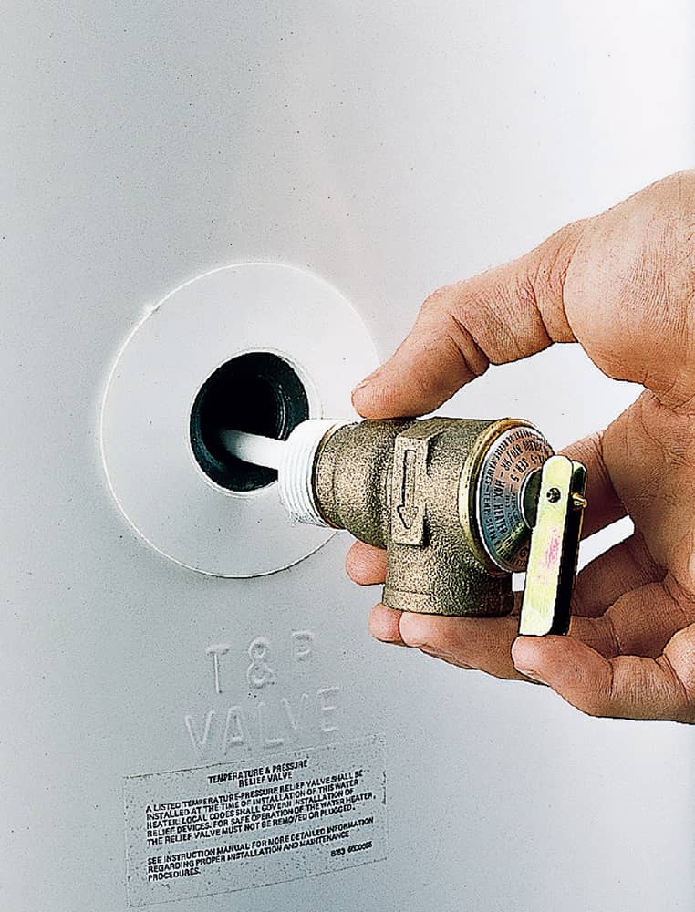
Attach a discharge tube to the T & P relief valve. You may use either copper pipe or CPVC drain pipe. Cut the tube so the free end is between 1 1/2 and 6” above the floor. If you have floorcoverings you wish to protect, add a 90-degree elbow and a copper drain tube that leads from the discharge tube to a floor drain.
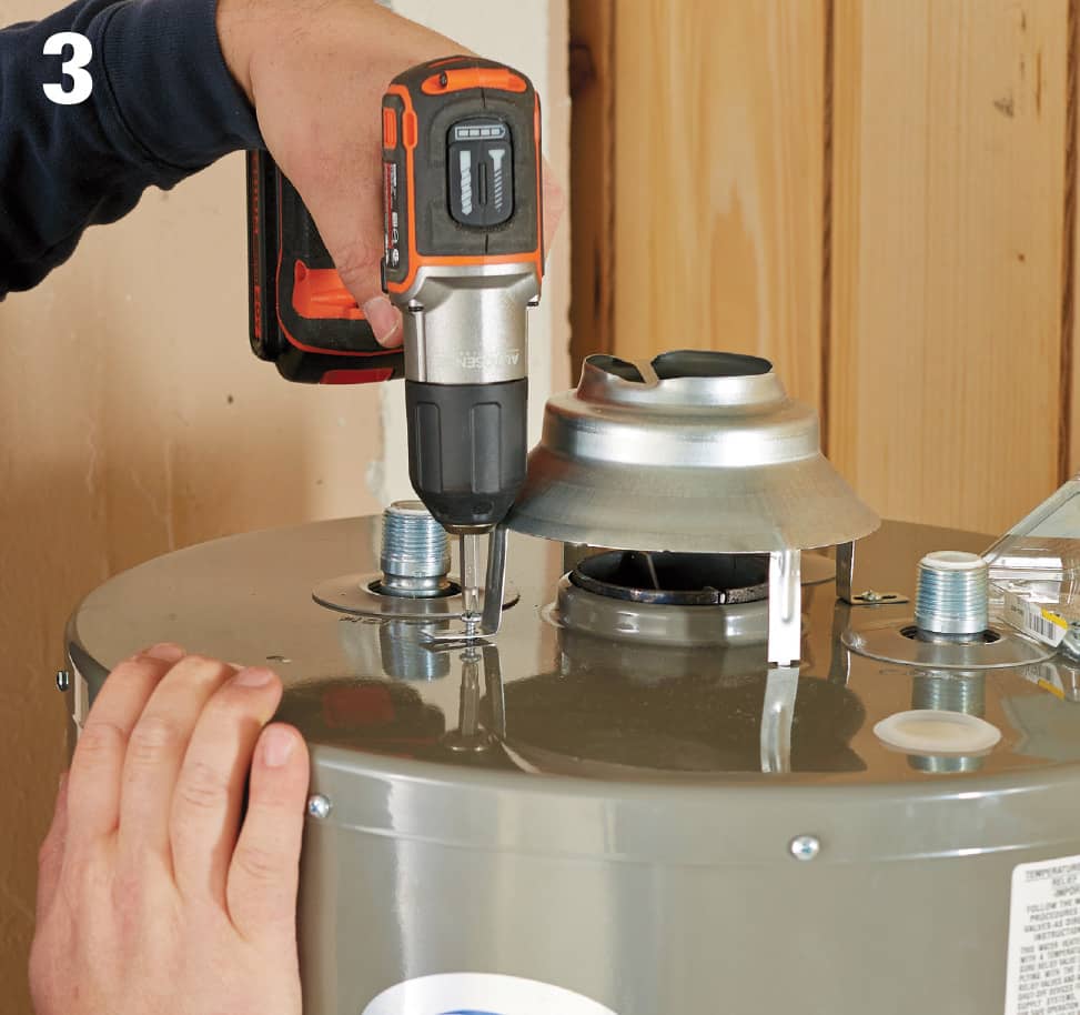
Attach the draft hood for the flue to the top of the unit with the provided hardware. Attach any other connector parts that are not preattached according to the manufacturer’s instructions.
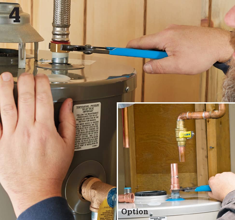
Attach approved supply connectors to the inlet and outlet ports at the top of the appliance. Flexible connectors are much easier to work with, but you may use copper tubing if you prefer. If using copper, you’ll need a red-coded copper nipple for the outlet port and a blue-coded copper nipple for the inlet port (inset photo).
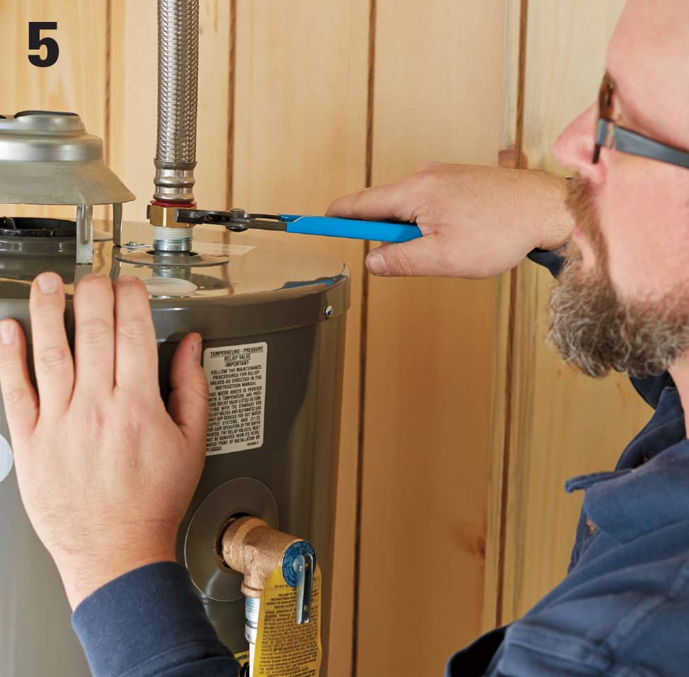
Join the supply connectors to the supply tubing with approved couplings. If the supply line feeding the water heater has no shutoff valve nearby, it is recommended that you add one. As long as there is a shutoff on the incoming supply side you do not need one on the outgoing (hot water) line.
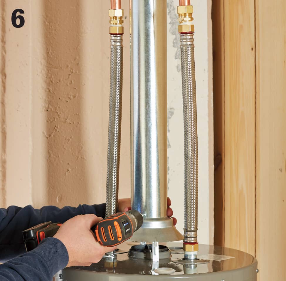
Assemble the vent and attach the end to the draft hood for the flue.
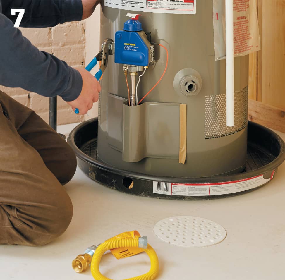
Begin making the gas connections. Working with gas pipes and tubing is dangerous and you should only attempt it if you have considerable experience in this skill area. If you are not comfortable working with gas pipe, hire a plumber to take on this part of the job. You’ll still save plenty of money by doing the rest of the work yourself. Begin by screwing the male-threaded union securely into the gas regulator port. Wrap gas-approved lubricating tape around the threads first. Tighten with channel-type pliers, taking care not to overtighten or cause undue pressure on the regulator.
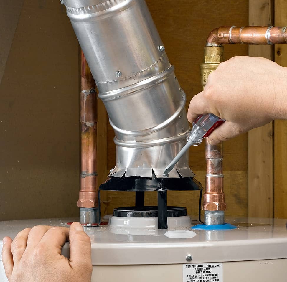
OPTION: If you are running a new vent, you will most likely need to use an elbow fitting and adjustable fittings to achieve the configuration you need. The new vent should be inspected and approved by your local building department.
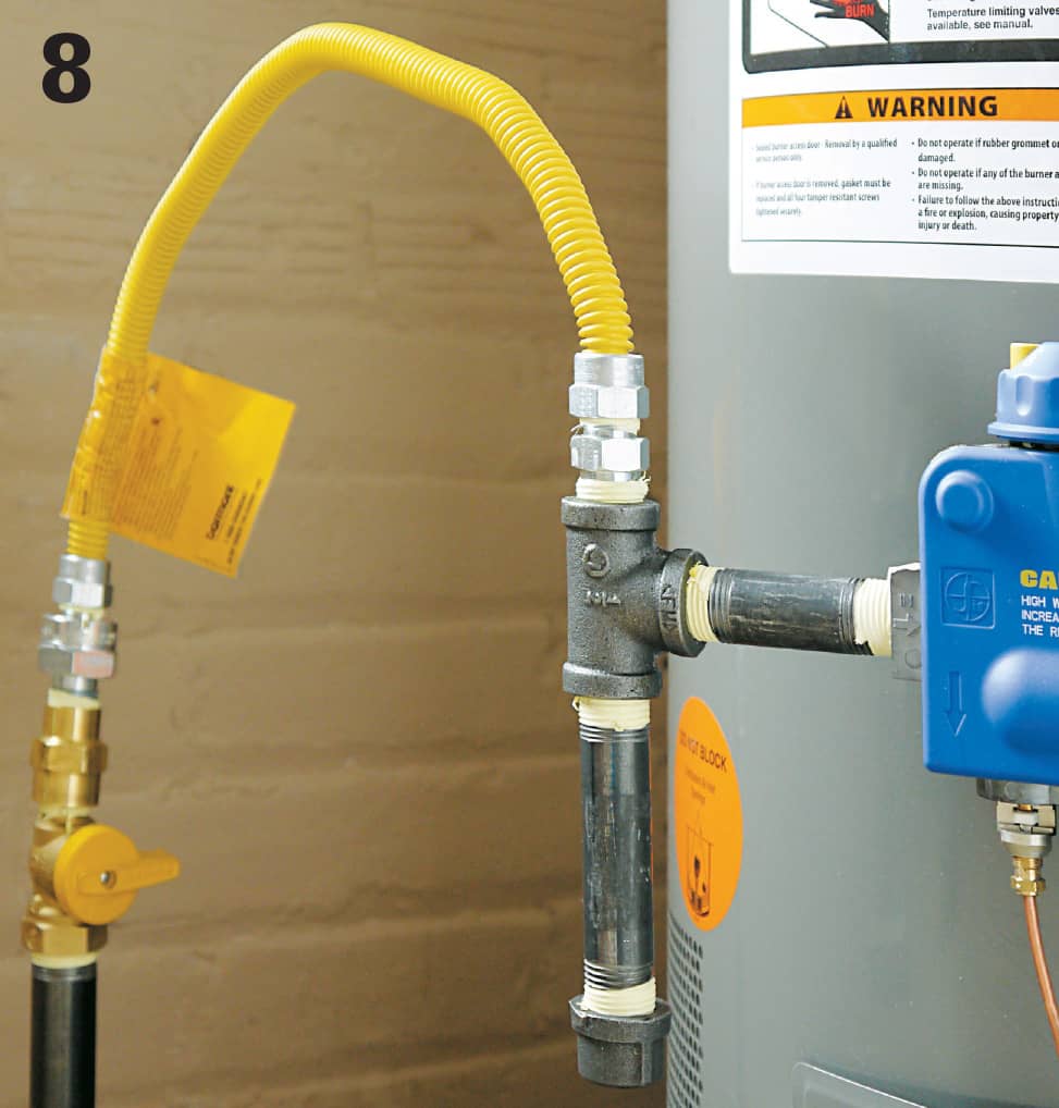
Connect a flexible gas supply tube to the port on a shutoff valve on the gas supply line. The shutoff must be within six feet of the appliance. Connect the other end to the union at the regulator. Wrap the threads in each threaded connection with three or four tight courses of gas-rated lubricating tape first. Include a sediment trap in the hook-up (see page 521).
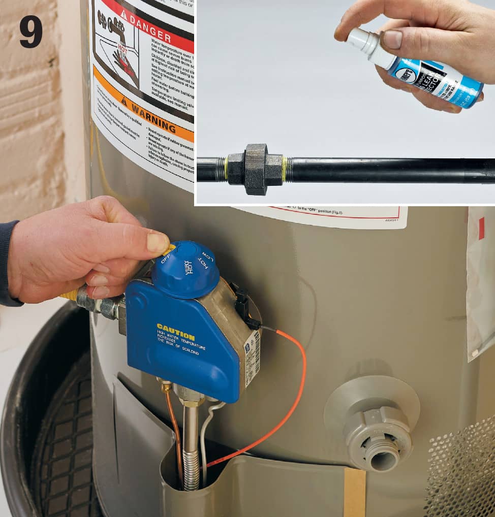
Turn on the gas supply and test the gas connections with testing solution (inset photo) to make sure there are no leaks—do not use dish soap or any other products that may contain chlorides. Make sure the tank drain valve is closed, then turn on the water supply and check for water leaks. Once you have determined there are no plumbing leaks, light the pilot light (the instructions are always printed on a label near the pilot light).
 Servicing Thermostats
A thermostat is a temperature-sensitive switch that automatically controls home heating and air-conditioning systems. There are two types of thermostats used to control heating and air-conditioning systems. Low-voltage thermostats control whole-house heating and air conditioning from one central location. Line-voltage thermostats are used in zone heating systems, where each room has its own heating unit and thermostat.
A low-voltage thermostat is powered by a transformer that reduces 120-volt current to about 24 volts. A low-voltage thermostat is very durable, but failures can occur if wire connections become loose or dirty, if thermostat parts become corroded, or if a transformer wears out. Some thermostat systems have two transformers. One transformer controls the heating unit, and the other controls the air-conditioning unit.
Line-voltage thermostats are powered by the same circuit as the heating unit, usually a 240-volt circuit. Always make sure to turn off the power before servicing a line-voltage thermostat.
A thermostat can be replaced in about one hour. Many homeowners choose to replace standard low-voltage or line-voltage thermostats with programmable setback thermostats. These programmable thermostats can cut energy use by up to 35%.
When buying a new thermostat, make sure the new unit is compatible with your heating/air-conditioning system. For reference, take along the brand name and model number of the old thermostat and of your heating/air-conditioning units. When buying a new low-voltage transformer, choose a replacement with voltage and amperage ratings that match the old thermostat.
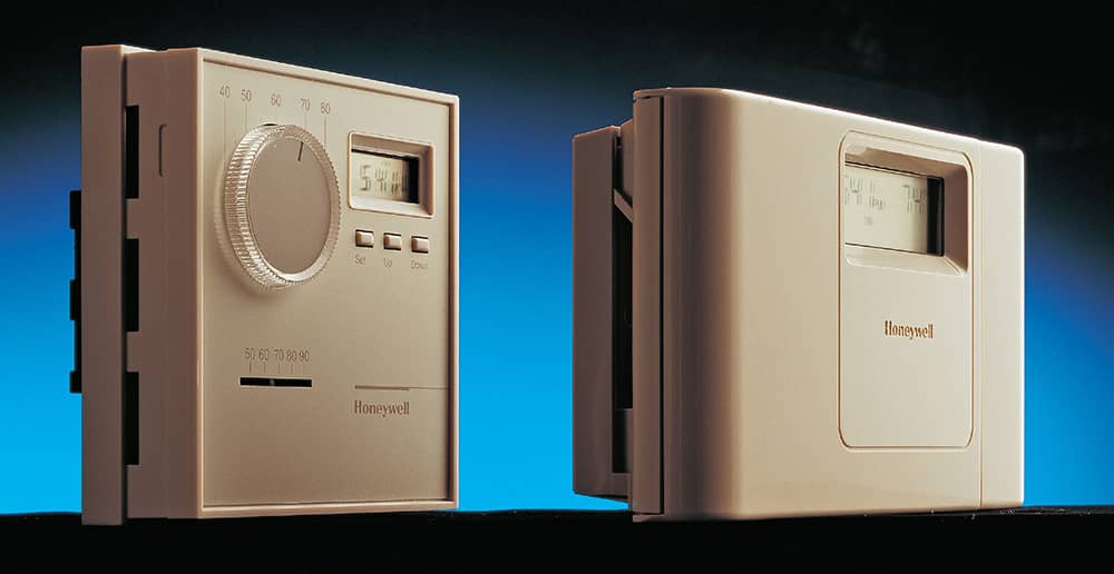
Electronic programmable thermostats can be set to make up to four temperature changes each day. They are available in low-voltage designs (right) for central heating/cooling systems and in line-voltage designs (left) for electric baseboard heating. Most electronic programmable thermostats have an internal battery that saves the program in case of a power failure.
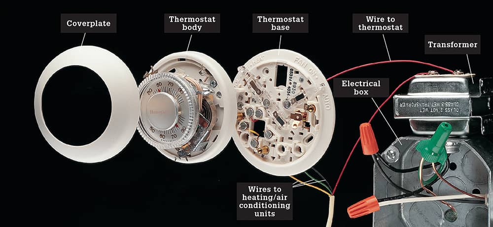
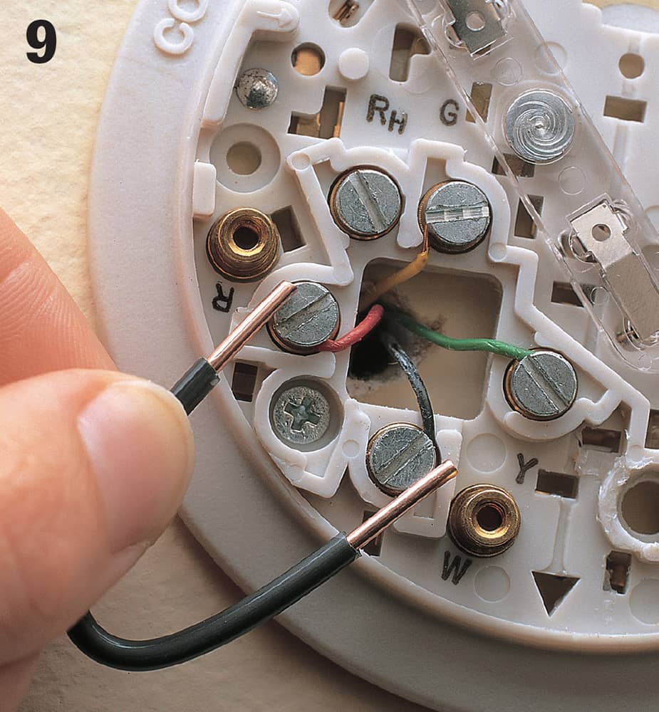
Low-voltage thermostat system has a transformer that is either connected to an electrical junction box or mounted inside a furnace access panel. Very thin wires (18 to 22 gauge) send current to the thermostat. The thermostat constantly monitors room temperatures, and sends electrical signals to the heating/cooling unit through additional wires. The number of wires connected to the thermostat varies from two to six, depending on the type of heating/air conditioning system. In the common four-wire system shown above, power is supplied to the thermostat through a single wire attached to screw terminal R. Wires attached to other screw terminals relay signals to the furnace heating unit, the air-conditioning unit, and the blower unit. Before removing a thermostat, make sure to label each wire to identify its screw terminal location.
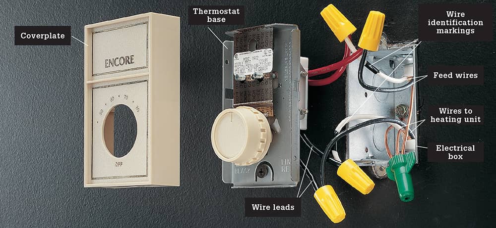
Line-voltage thermostat for 240-volt baseboard heating unit usually has four wire leads, although some models have only two leads. On a four-wire thermostat, the two red wire leads (sometimes marked LINE or L) are attached to the two hot feed wires bringing power into the box from the service panel. The black wire leads (sometimes marked LOAD) are connected to the circuit wires that carry power to the heating unit.
How to Inspect & Test a Low-voltage Thermostat System
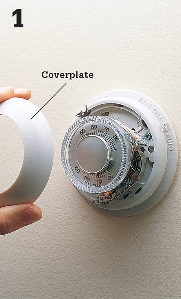
Turn off power to the heating/air-conditioning system at the main service panel. Remove the thermostat coverplate.
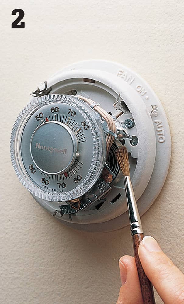
Clean dust from the thermostat parts using a small, soft-bristled paint brush.
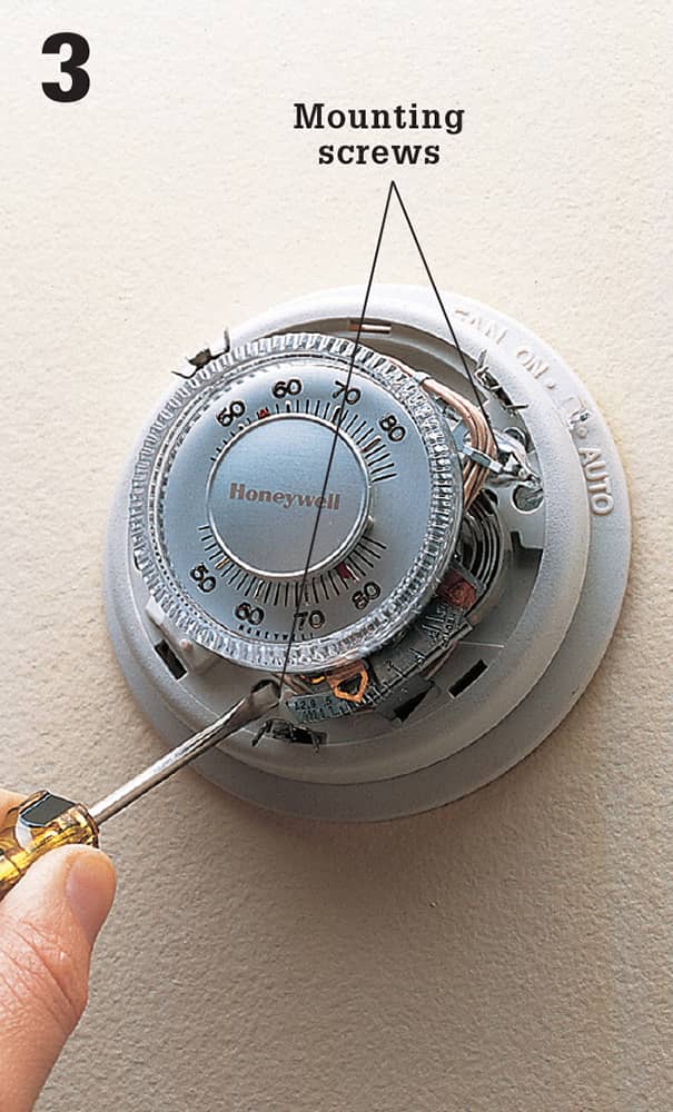
Remove the thermostat body by loosening the mounting screws with a screwdriver.
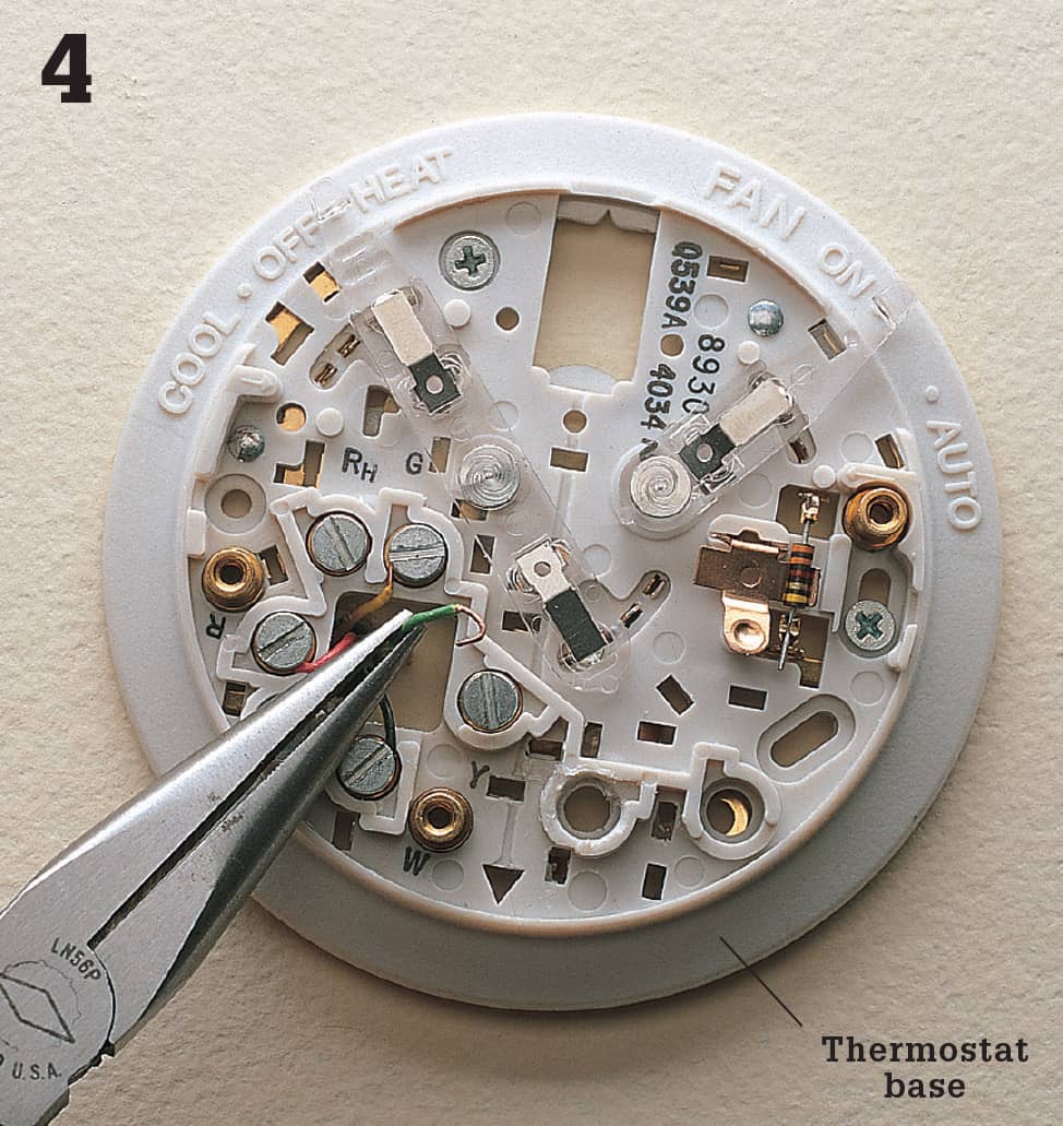
Inspect the wire connections on the thermostat base. Reattach any loose wires. If wires are broken or corroded, they should be clipped, stripped, and reattached to the screw terminals.
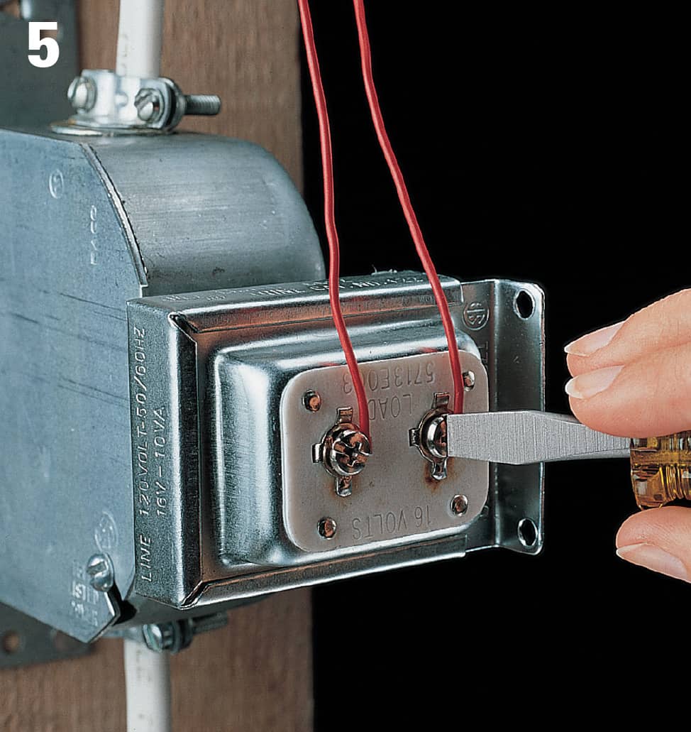
Locate the low-voltage transformer that powers the thermostat. This transformer usually is located near the heating/air-conditioning system or inside a furnace access panel. Tighten any loose wire connections.
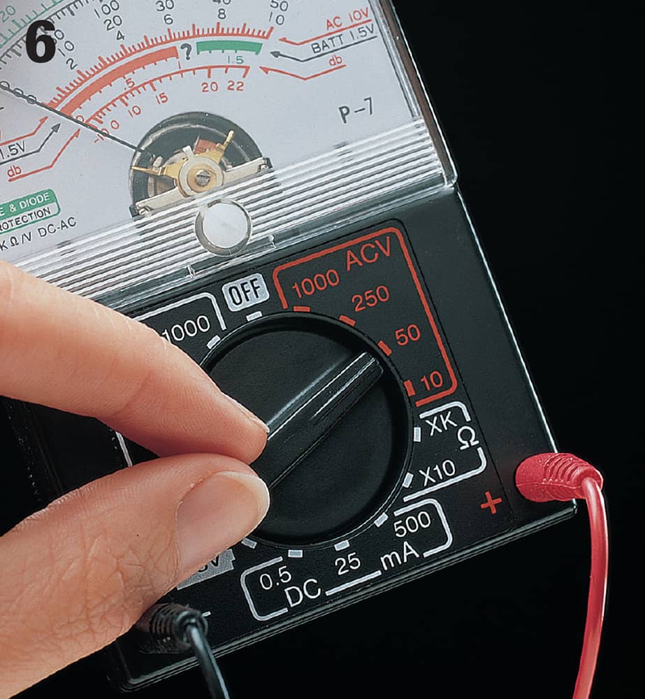
Set a multimeter to the 50-volt (AC) range. Turn on power to the heating/air-conditioning system at the main service panel.
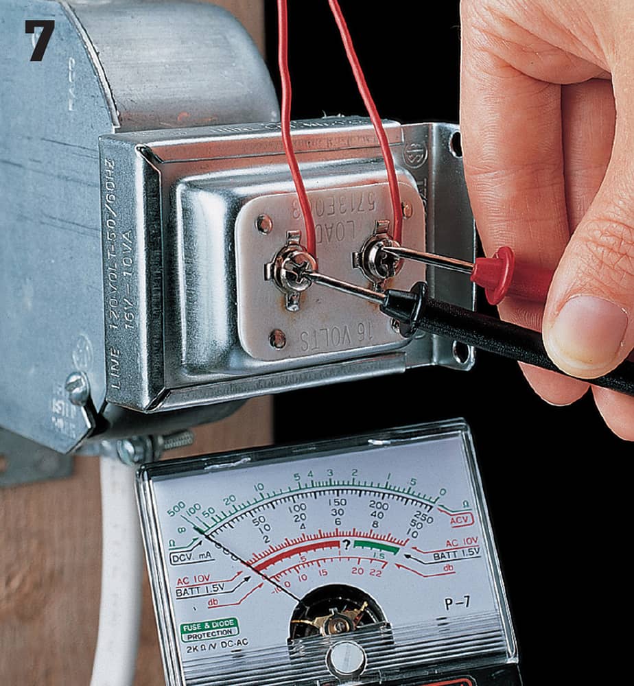
Touch one probe of multimeter to each of the low-voltage screw terminals. If tester does not detect current, then the transformer is defective and must be replaced (page 543).
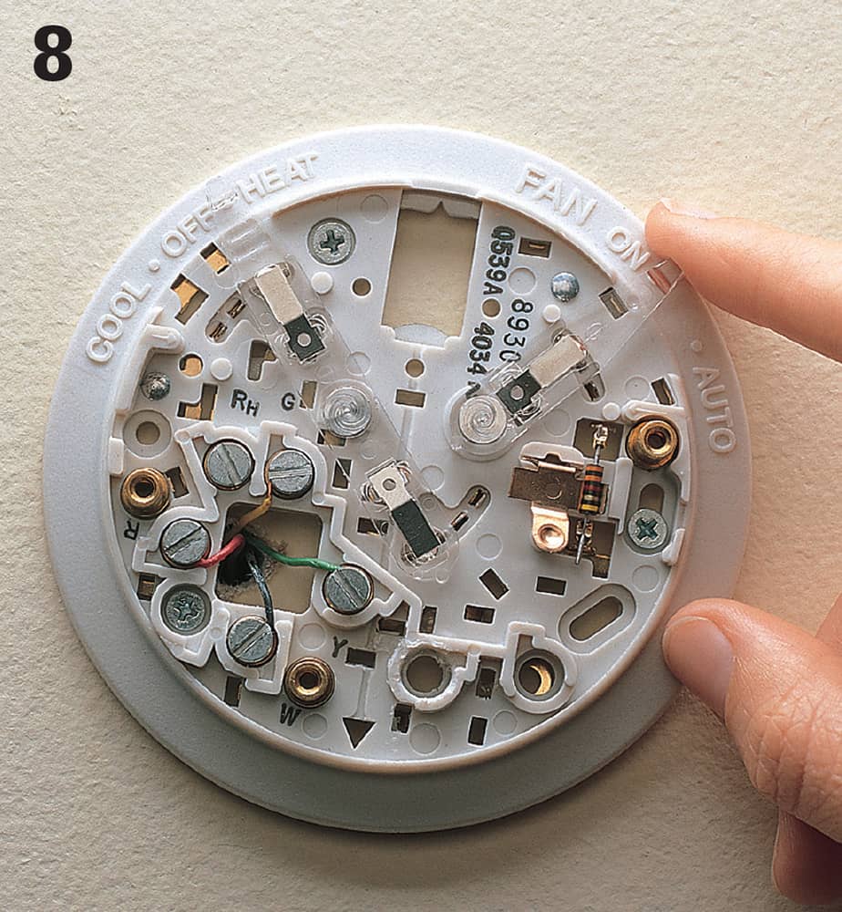
Turn on power to heating system. Set thermostat control levers to AUTO and HEAT.

