Chapter 8
Software Innovations
Just as network hardware and silicon innovations have been advancing, so have innovations in networking software. As the network infrastructure evolves, and greater and greater demands are placed on the network, the software that helps to define and shape the network also continues to evolve. This chapter examines that evolution, and peers more deeply into how Cisco’s networking software infrastructure is changing to adapt to the ever-growing demands placed upon it.
This chapter explains the following:
Networking software innovations with Cisco IOS XE
Cisco trustworthy systems and the importance of secure infrastructure
The move to intuitive networking
The Importance and Evolution of Networking Software
So often today, you hear about software-defined architectures and capabilities. And in many ways, the movement toward systems that are defined by software—and which can evolve at the speed of software—has taken the industry by storm. Software-defined systems offer many solutions to the problems faced by network managers, and help the network infrastructure to take on new challenges and rapidly adapt, assisting organizations large and small to enable new network functionality to help drive their businesses forward.
And yet, networking software always existed as a core foundation of the success of the networking industry, and has long served as the foundation upon which the achievements of the network infrastructure—and the organizations that leverage that infrastructure—have been based.
Let’s examine the origins of the software foundation upon which today’s modern network infrastructures are built, and how that software foundation is evolving.
There are many places today that networking software is deployed. Few if any, however, are as ubiquitous, or as critical for the proper operation of the enterprise network, as the code running in network devices themselves—the network operating system. As the most ubiquitous network operating system in use globally, Cisco IOS is a critical element of hundreds of thousands of networks worldwide, and forms an underpinning of the overall network infrastructure both of organizations and of the Internet itself. From its origins with Cisco in 1984 to the modern day, IOS evolved to serve the needs of many organizations—in healthcare, manufacturing, education, government, and every industry large and small.
Figure 8-1 shows the evolution of Cisco IOS, along with an approximate timeline of IOS deployment, and several of the key enterprise platforms that have leveraged Cisco IOS over the years.
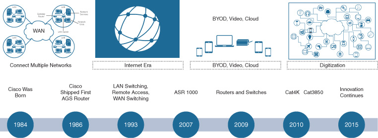
Cisco IOS: Origins and Evolution
Initially, IOS was created to run on a single-CPU system, in products such as the Cisco 2500 and 4000 Series routers. Within these platforms, which were fundamentally software based, that CPU served to operate all three “planes of existence” which any networking device must accommodate:
Data plane: The data plane deals with the basic movement, and forwarding, of data packets through the device. In the initial Cisco IOS software–based router implementations, each packet was handled solely by software. An incoming packet generated an interrupt to the CPU when it arrived, and the CPU suspended whatever other tasks it was doing, serviced the packet (forward, drop, remark, etc.), and then resumed its former tasks.
Control plane: Any networking device must interact with other devices in the network to form a system. This interaction takes place at Layer 2, using protocols such as Spanning Tree Protocol (STP) or Per-VLAN Rapid Spanning Tree (PVRST+), and/or at Layer 3, using protocols such as Open Shortest Path First (OSPF), Enhanced Interior Gateway Routing Protocol (EIGRP), Intermediate System to Intermediate System (IS-IS), or Border Gateway Protocol (BGP). The purpose of these protocols is to establish the forwarding path along which traffic is sent once it arrives at the network devices involved, to rapidly resolve new forwarding paths when changes in the network topology might arise (from device or link failures, for example), and to avoid uncontrolled network loops which could interrupt or interfere with network operation.
Management plane: It is critical that the network is both manageable and able to be monitored for correct operation. Traditionally, this was done using the command-line interface (CLI) for human interaction and scripting, as well as protocols such as Simple Network Management Protocol (SNMP) for network monitoring.
Cisco IOS was created to provide excellent capabilities at all three of these layers of network operation.
With the initial implementation of Cisco routers with lower-speed interfaces and less total interface density (for example, with a single 10-Mbps Ethernet port and single or dual T1 ports on a Cisco 2500 router), a single CPU handled all of these tasks—forwarding data, running the appropriate control plane protocols as designated by the network manager, and allowing for monitoring and control of network operations.
However, as network capabilities, and speeds and feeds, evolved, the Cisco IOS software managing the network had to evolve as well. Let’s examine the evolution of all three planes of operation within Cisco IOS, and illustrate how they changed over time.
Evolution of the Cisco IOS Data Plane
The efficiency of forwarding packets in the data plane—the ability of a routing device to handle ever-greater interface speeds as well as ever-increasing interface densities—required improvement as network systems continued to evolve.
This fostered the evolution of what became known as Cisco Express Forwarding (CEF), an innovative solution where the common manipulations that a router was taking for a given packet (rewrite MAC address, select forwarding interface, etc.) were precomputed into a table, allowing for more rapid packet manipulation and dramatically speeding up the forwarding process, while making it more efficient and reducing total CPU processing load. CEF was a key innovation when introduced, enabling Cisco routers to adapt to the increasing performance of network systems and link speeds.
Another change that came about due to the necessity to accommodate higher-speed router interfaces was the movement from centralized to distributed forwarding as an option. This involved the movement of the data plane away from a single-CPU architecture, and the deployment of distributed forwarding systems within the router platform. This was seen on the Cisco 7000 and 7500 Series routers, and later on the Cisco 12000 Series platforms, among others, which employed specific line cards with distributed forwarding capabilities.
These enabled the line cards to provide local CPUs (and later, custom application-specific integrated circuits [ASICs]) to operate the data plane locally—with the central router CPU running the control plane to determine the network topology (and adapt to changes in that topology), and then in turn programming the CEF forwarding tables on the line cards for distributed traffic forwarding. While lower-end routers continued to use a single central CPU for all tasks (as long as that CPU was sized accordingly for the interfaces it needed to handle), higher-end routing platforms typically moved to a distributed forwarding model.
The move to distributed forwarding required Cisco IOS to evolve. Now it was necessary to coordinate the function of packet forwarding across multiple line cards in the system, continuously monitor the state of those line cards, and manipulate the distributed forwarding model across those line cards as the network infrastructure was established by the network manager, and as it operated autonomously throughout the lifetime of the network device. This is a far more complex task than performing all actions within a single CPU, yet the basic design of Cisco IOS was robust enough to accommodate this change—and accommodate it, it did.
In the mid-1990s, Cisco made the move into switching, rounding out its routing portfolio with devices that could scale to much higher speeds, and to much greater density of interfaces. Some of the companies that Cisco initially acquired to move into the switching arena included Crescendo (basis of the Catalyst 5000 switch family), Kalpana (precursor to the Catalyst 3000 and later 3x50 switch families), and Grand Junction (forerunner of the Catalyst 1900 and later the 29x0 switch families).
As this move into switching was made, Cisco IOS had to adapt again. Switches handle many interfaces—initially dozens, and as switching evolved, scaling into hundreds—and even a distributed-forwarding CPU-based model was unable to keep pace. Switches rapidly demanded the evolution, first of field-programmable gate arrays (FPGAs), and later of custom ASICs, to perform the data plane packet-forwarding functions of the device. No longer could any CPU-based system—even with distributed forwarding—keep pace with the demands that switches placed on the network data plane.
Once again, this required Cisco IOS to evolve. IOS had to adapt to interface with, and properly program, silicon-based forwarding, where the actual packet manipulation was taking place in hardware, and the switch’s CPU was instead involved with calculating the forwarding tables, and then in turn programming the underlying forwarding hardware to drive the actual processing of network packets as they arrived at the device.
Initially, switches operated in hardware at Layer 2 only, with routing tasks (forwarding traffic between subnets) still taking place on a CPU. The switch hardware recognized any packet with a destination of a router MAC or virtual MAC address (in the case of Hot Standby Router Protocol [HSRP] or Virtual Router Redundancy Protocol [VRRP], for example), and forwarded that frame to the software-based portion of the switch for packet forwarding or handling. This was the case, for example, with the Catalyst 5000 switch when used with a Route Switch Module (RSM). The RSM was a line card installed into one of the slots of the Catalyst 5000 switch, allowing the platform to perform Layer 3 routing tasks via the RSM, in addition to the Layer 2 switching tasks performed in hardware by the installed Supervisor module.
While effective, this was cumbersome as well as limited in performance. Initial switch platforms such as the Catalyst 5000 (and later its successor, the Catalyst 5500) ran a Layer-2-oriented operating system descended from Crescendo lineage (Catalyst OS, or CatOS), with the RSM running IOS. This presented the network manager with two CLI-based user interfaces he or she had to interact with, complicating the task of network deployment and management.
In addition, the linkage between the RSM and the Catalyst 5000 backplane was only 400 Mbps (2 × 200-Mbps channels), thus underperforming the 1.2-Gbps backplane of the Catalyst 5000 switch platform, and as well the RSM was CPU-based and thus limited in the total performance it provided.
Over time, CatOS was phased out in favor of Cisco IOS as the single operating system operating on switches (this change happened on the successor platforms to the Catalyst 5500—namely, the Catalyst 4500 in the Supervisor 4 timeframe, and the Catalyst 6500 with the Supervisor 2 and Supervisor 720). This not only made the network easier to deploy and manage, it also opened the door to more rapid innovation on a single network operating system. Some switch platforms, such as the Catalyst 3500 Series switches, were introduced with only IOS as a software option, simplifying their deployment and use.
Also over time, the ever-increasing speeds and feeds involved with switching, and the increasing use of Layer 3 for network segmentation, required the movement away from software-based routing solutions into true hardware-based packet forwarding, for both Layer 3 and Layer 2.
An example of this is seen with the evolution of the Catalyst 6500 switch platform. Initially introduced to the market in early 1999 as the Catalyst 6000, the switch initially was Layer 2 only, much like its Catalyst 5500 precursor, and employed a software-based Layer 3 routing module known as the Multilayer Switch Module (MSM) in conjunction with the switch’s Supervisor 1 module (which handled all Layer 2 tasks). However, this was a short-term solution only, because the Catalyst 6000 with its 32-Gbps backplane (as opposed to the single 1.2-Gbps backplane of the Catalyst 5000, or a 3 × 1.2-Gbps backplane of the Catalyst 5500) easily outclassed the performance of the MSM.
Accordingly, Cisco developed the Policy Feature Card (PFC), an ASIC-based daughtercard that sat on the Catalyst 6500’s Supervisor 1A module, and which handled all Layer 3 routing tasks. Leveraging Cisco IOS, the PFC employed a new switching mode called Multilayer Switching (MLS), in which the first packet of any given traffic flow (as tracked by a hardware-based NetFlow table) was punted to the switch’s central CPU, and routed in software. The CPU then installed an entry in the switch’s hardware NetFlow table, allowing all subsequent packets matching that flow to be forwarded in hardware by the PFC, including all packet manipulations required by Layer 3 routing.
In addition, the matching of traffic for functions such as access control lists (ACL) was done now in hardware, using ternary content-addressable memory (TCAM), allowing ACL matches for functions such as packet filtering for security, or the application of packet remarking for quality of service (QoS) entries, to be done in hardware. Finally, the speed of Layer 3 routing and Layer 2 forwarding on the data plane could match up. Now, network managers were free to design their networks according to the way they desired traffic to be routed and manipulated, not according to the restrictions imposed by Layer 2 and Layer 3 boundaries and the associated performance limits in network devices.
Of course, Cisco IOS had to evolve to meet these needs. The split between functions that ran on the control and management planes of the device—and thus ran on the device’s CPU—and the functions that ran on the device’s data plane were becoming ever more clear.
This trend continued as the limits of what was possible with the MLS switching model were reached. Sending the first packet of each flow to the device’s CPU, and having to route that packet in software—along with the limited size of the NetFlow hardware cache table (nominally 32K flows on PFC1A)—required switching technology to move forward once again, and required IOS to keep pace.
This led directly to the development of Cisco forwarding hardware for switches that employed CEF switching directly in hardware. On the Catalyst 6500, this was first seen with the Supervisor 2 module, and was employed with all subsequent Supervisors on that platform, as well as all other Layer 3 switches within Cisco’s product lineup. Now, it became necessary for Cisco IOS to compute both the Routing Information Base (RIB) and the Forwarding Information Base (FIB), and then process and program the corresponding CEF table directly into the switch hardware. Now, the separation between the data plane (packet forwarding in hardware) and the control and management planes in software was complete.
The evolution of Cisco IOS (and the described innovations it drove along the journey) was key not only in moving the state of networking forward but also in allowing the networking industry—and all the industries that depend on networking as their “life blood” for operation—to evolve and grow. In the world today, data moves around with dizzying speed, zipping across 10-Gbps and 100-Gbps interfaces around the globe, across networks that are constantly growing in terms of breadth and depth. Cisco IOS, and the data plane innovations, continues as one of the key linchpins of the network infrastructure that allows this growth to happen.
Evolution of the Cisco IOS Control Plane
Just as the data plane of Cisco IOS evolved to keep pace with, and drive, changes in the network infrastructure, so has the IOS control plane needed to evolve.
Over the years, Cisco has developed a rich evolution of the control plane options made available to network managers, and this evolution continues today. Beginning with simple protocols such as basic Spanning Tree Protocol (STP) for Layer 2 and Routing Information Protocol (RIP) for Layer 3, Cisco IOS now supports a broad range of control plane protocols to adapt to a wide variety of different network requirements and topologies.
At Layer 2, Spanning Tree began as a simple way to avoid loops in Layer 2 networks. Because a frame at Layer 2 is not altered as it is forwarded (unlike routed packets, which have a TTL [Time To Live] value decremented at each hop), uncontrolled loops in a Layer 2 network can become very destructive to network operation. Spanning Tree is of course designed to prevent such events (known as broadcast storms) from occurring, by blocking links as needed to establish only a single “tree” for Layer 2 packet forwarding—a tree rooted at the STP root node and radiating outwards, with redundant links leading back to the root blocked as needed, and with the ability to unblock such links if and as a change in the Layer 2 topology occurs.
The capabilities for handling Layer 2 networks, and the continuing evolution of the protocols involved with this, are addressed in more detail in Chapter 9, “Protocol Innovations.”
Likewise, Layer 3 networks evolved over the years. Beginning with RIP, routing quickly developed the need for more advanced networking protocols—ones that could handle classless addressing (i.e., routing based on more than just the traditional Class A (/8), Class B (/16), and Class C (/24) network boundaries), that could handle network address summarization, and that could provide much faster reconvergence as well as be used for routing between, and within, independent routing domains. This drove the evolution of routing protocols such as OSPF, EIGRP, IS-IS, and BGP—all of which Cisco IOS was key to driving, and providing to the broad marketplace of networking solutions available to the modern network manager.
The control plane solutions provided by Cisco continue to evolve even today. Again, this evolution is examined in more detail in the next chapter.
Evolution of the Cisco IOS Management Plane
As with the data plane and control plane operation of a network device, the needs of the device’s management plane—and the corresponding needs of the network management systems—continued to evolve markedly over time.
Cisco IOS needed to keep pace with this evolution, and help drive it.
Beginning with the basics of the CLI, Cisco established one of the most widely recognized and used interfaces in the networking industry. The Cisco IOS CLI is known to hundreds of thousands of network managers worldwide, and is the basis of network management and operation in countless deployments. The Cisco IOS CLI is used not only for manual operation of network devices, but with scripting solutions for driving automation.
Likewise, SNMP as used within Cisco IOS is the basis for many network management solutions, serving to allow the remote monitoring of network device health, traffic handling and forwarding, and overall network operation in many deployments worldwide.
And yet, for all their utility, the use of the device CLI and protocols such as SNMP also introduces many issues. These include complexity in device operation (due to many CLI variations and many commands necessary for device operation) and excessive CPU loading of the device for network monitoring and management.
In response, the industry, and Cisco IOS, evolved solutions to meet these needs, going well beyond what the traditional CLI + SNMP approach to managing the device—and the network—provide. These capabilities, and this evolution, are examined in greater detail in Chapter 13, “Device Programmability.”
Evolution of Cisco Networking Software
So far, this chapter has examined how Cisco IOS evolved to address the continuing and ever-growing requirements of the data plane, control plane, and management plane of the network. An additional important consideration is how Cisco’s networking software overall needed to evolve to tackle the various, and very distinct, markets that it serves.
Broadly, these markets are divided into three major categories:
Enterprise: This category is the most all-encompassing, spanning everything from small businesses to major, globe-spanning organizations, and including both private businesses and many public and governmental bodies. While this set of organizations is often subcategorized into Commercial, Small Enterprise, Large Enterprise, Global Enterprise, Public Sector, and the like, as a whole these organizations share several important characteristics. They all employ networks that are defined, implemented, and operated by a single holistic organization, usually by a single network team focused on the outcomes that the network involved helps to drive for that organization—be it small, large, or global in nature.
Service Provider (SP): This category is focused on organizations that build a network to service the needs of other organizations (as well as themselves). Typically, SPs are focused on providing network functionality that other organizations can leverage, typically at a cost. This includes providing connectivity services as well as a possible range of ancillary services (for example, content distribution, security services, or other related functions). Over the years, SPs evolved to much more than just providers of basic connectivity for wide-area networks. Nevertheless, they are broadly categorized as organizations that build networks for others to leverage.
Data Center (DC): Both enterprises (of all sizes) and service providers need to operate data centers, which house the multitude of servers and services that the network provides access to for the organization. Data centers have a unique set of requirements in terms of scale, performance, functionality, and fault tolerance that set them apart from a traditional enterprise or service provider network, and often require a separate and distinct network design, created to service the precise needs of the data center environment.
While examples certainly exist of “cross-overs” between these three broad categories—a common example being the WAN backbone of a large, multi-departmental enterprise organization that may actually begin to resemble more of a service provider deployment model—the preceding major categories define three distinct and unique sets of use cases, each corresponding to a particular associated set of network requirements around (among other variables) speeds and feeds, resiliency and fault tolerance, expansion requirements, Layer 2 and Layer 3 traffic handling, and more.
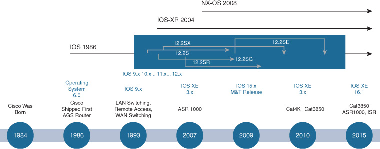
Accordingly, Cisco’s network operating system software strategy evolved over the years to address these three unique markets as follows:
Enterprise: The Enterprise market is largely served by Cisco IOS, which has now evolved into Cisco Open IOS XE (more details following). Open IOS XE (often abbreviated to simply IOS XE) is the direct evolution of Cisco IOS, building on this legacy and set of capabilities while evolving to support a next generation of enterprise-focused network designs, solutions, and outcomes. Given the focus of this text on examining Cisco Digital Network Architecture (Cisco DNA) and its impact on the evolution of the enterprise network, special attention is paid here to Cisco IOS XE and its capabilities and evolution. Open IOS XE is called “Open” because it embraces, and enables within the enterprise network, several attributes of open networking, including YANG data models, open industry-standard interfaces such as NETCONF and RESTCONF, and the ability to deploy containerized applications onto distributed network devices.
Service Provider (SP): While Cisco IOS (and now, IOS XE) is certainly used in various places in SP networks, Cisco’s SP-focused network operating system software is IOS XR. Designed with the unique scale, performance, and functionality needs of SPs in mind, IOS XR powers some of the largest and most complex SP networks in the world. Built from the ground up to provide the capabilities that SPs demand most, IOS XR sheds many of the diverse protocols and capabilities that need to be supported in enterprise environments for a more focused set of capabilities that are designed to service the world’s largest networks. While some very large enterprises (especially those resembling SPs in some aspects, as previously mentioned) also deploy IOS XR–based platforms, the primary focus of IOS XR remains the core SP market.
Data Center (DC): The demanding environment of the modern data center drives several unique requirements. These include (but are not limited to) widespread use of Layer 2 for server-to-server intra-DC connectivity, very rapid network failover and recovery requirements, and the need to accommodate very high (and ever-growing) performance needs, typically pushing the boundaries of what is possible for network connections. To meet these demands, Cisco created NX-OS, focused on the needs of the modern—and ever-evolving—data center. Because both enterprises and service providers deploy their own DCs, or host DCs for others, NX-OS is used in both types of deployments, within the data center and focused on the outcomes that data centers require.
The evolution of these various operating systems—IOS XE, IOS XR, and NX-OS—is illustrated in Figure 8-2.
The Evolution of Cisco IOS to IOS XE
While Cisco IOS has served many tens of thousands of customers worldwide well for over three decades, an evolution of the basic architecture of Cisco IOS was undertaken several years ago to help IOS continue to adapt to an every-changing world, and an ever-evolving set of network requirements.
What factors came into play as the evolution of Cisco IOS was undertaken?
First, the need to provide a level of modularity for IOS was desirable. Traditionally, Cisco IOS was implemented and operated as a single, monolithic code base, with direct access to the underlying hardware of the platform on which it ran. While this model evolved over the years (for example, to address the separation of data plane and control plane detailed previously in this chapter) the basic structure of Cisco IOS was maintained—a single software code base, running on a device CPU, with direct access to the underlying network hardware.
For most enterprise network tasks, this worked very well over the years. Nevertheless, changes in network and device operational practices made some modifications in Cisco IOS desirable. As well, the ever-changing “state of the art of what’s possible” made such changes more practical to realize than they were in the past. As well, the continuing evolution of network designs made alterations to what IOS needed to be capable of more urgent than had previously been the case.
Taken together, all of these elements created the necessity for Cisco IOS to evolve. IOS XE is the result of that evolution.
Cisco IOS XE in a Nutshell
Fundamental shifts have occurred in the enterprise networking landscape. These include the move from networks that only had to concern themselves with moving data, voice, and video, to more modern networks that have to encompass mobility, the deployment of ever-increasing types and numbers of IoT devices and applications, and the accommodation of cloud capabilities, all while also addressing the manifold security requirements of the modern enterprise. Taken together, these constitute a new era of networking, as illustrated in Figure 8-3.
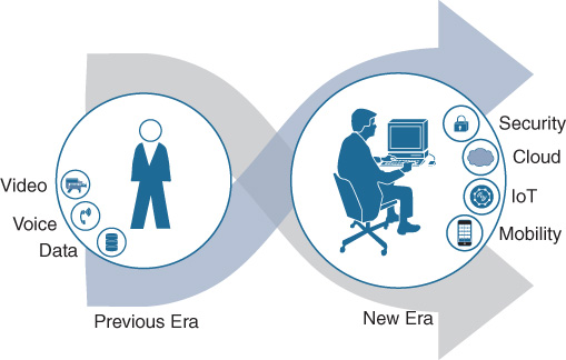
This is the era, and the trends, that Cisco IOS XE was created to address.
IOS XE set out to evolve the IOS infrastructure. The fact that this is an evolution is critical. There are tens of thousands of network professionals that know Cisco IOS inside and out—and many more networks that they support that depend on Cisco IOS, and the features and capabilities it provides, every day. Thus, one of the first goals of IOS XE was to provide an evolutionary path both for these networks and for the network managers and operators that implement and support them, while allowing the introduction of network technologies, new capabilities, and new network deployment modes and operating paradigms.
To evolve IOS to the next level of functionality and capability, it was important to set IOS XE on a strong foundation. IOS XE is implemented on top of a Linux kernel, providing a robust foundation that allows for extensibility, supports the use of multicore CPU processing, and sets the stage for hosting of additional applications and containers on the same platform that operates the core IOS XE set of processes and functions.
On top of that foundation, the core IOS XE functions operate within the context of IOSd, the IOS daemon that runs the core set of networking capabilities that Cisco IOS users and network managers depend on. Over the many years during which Cisco IOS evolved, IOS implemented hundreds of different capabilities, functions, and protocols that network managers use to create, define, operate, and manage their networks. You name a function provided by IOS, and somewhere in the world there is a network that leverages it, and a network manager that depends on it.
While not every function provided by traditional Cisco IOS is necessarily supported in IOS XE, most functions and capabilities are. This provides an important bridge in terms of functionality that network managers require to support business continuity and maintain operational discipline and control in their network infrastructures.
IOS XE is also designed to leverage the evolving hardware platforms that are in use in today’s—and tomorrow’s—network infrastructures. IOS XE is flexible enough to be implemented on CPU-only architectures (as often found in lower-end routers), as well as to leverage the heavily ASIC-based, silicon forwarding infrastructures found in many higher-end routing platforms (and virtually all switching platforms), including such advanced capabilities as multiswitch stacking, in which multiple switches are connected together to operate as a single, unified system, such as with StackWise-480 on the Catalyst 3850, 3650, and 9300 switch platforms and StackWise Virtual on selected versions of the latest Cisco Catalyst 9000 Series switch platforms.
IOS XE is also designed to be able to leverage the multicore CPU architectures and capabilities that are often employed in platforms today, distinct from the single-core CPU platforms of yesteryear. Leveraging such multicore CPU capabilities, where needed, required a fundamental rework of many Cisco IOS software capabilities and processes. The move to Cisco IOS XE provided this capability.
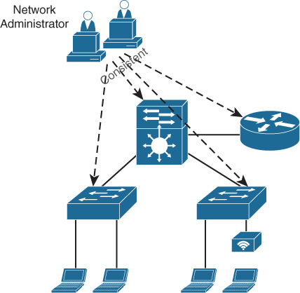
Overall, IOS XE set out to ultimately be a single OS that drives consistency in enterprise network deployments and, at the same time, drives simplified network administration, enabling an accelerated software lifecycle management capability with a similar CLI to older IOS variants, but enabling a whole new set of additional capabilities with modern interfaces such as NETCONF, RESTCONF, and Python scripting capabilities—thus moving IOS device and network management into the 21st century, and beyond.
Figure 8-4 illustrates this consistency. Cisco IOS XE enables the rapid deployment of new solutions, allows for simplified network administration, and provides streamlined software lifecycle management capabilities and ease of scripting, all while providing a familiar IOS CLI and allowing for a rapid adoption and learning curve.
Cisco IOS XE: Delving Deeper
To deliver on some of the key goals of IOS XE, an evolution of the IOS architecture was required. This actually took place over several IOS variants over a period of a few years, as illustrated in Figure 8-5.
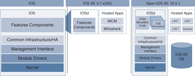
Starting with the basics of Cisco IOS operating as a single monolithic code base, an evolution began with the first variants of IOS XE (the 3.6.x and 3.7.x train), which separated out the various feature components of IOS into IOSd, and allowed for the co-hosting on the IOS XE platform of other applications, such as Wireless Control Module (WCM) and Wireshark.
Continuing and accelerating this evolution, the IOS XE 16.x train introduced several key new capabilities for IOS XE. These included the separation of several key functions from the IOS XE monolithic code base (allowing these to operate as separate threads of execution on top of the IOS XE underlying kernel) and providing an in-built database function against which IOS XE processes could checkpoint their various data structures as they were created and used.
In addition, IOS XE expands the application hosting ecosystem to include a framework for support of container-based applications to operate and be co-hosted on the IOS XE platform involved.
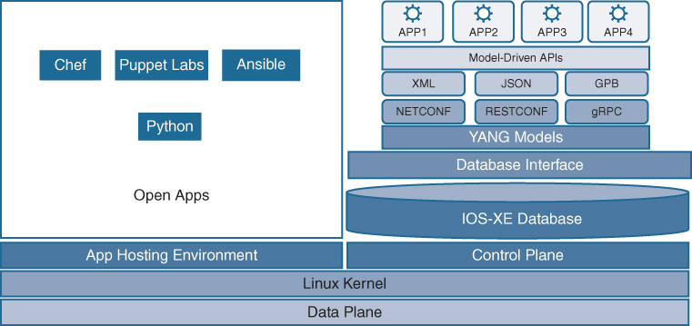
Figure 8-6 outlines these three key architectural enhancements enabled with IOS XE 16.x—namely, IOS subsystems, the IOS XE Database, and support for containers for application hosting.

Let’s examine each of these architectural enhancements provided by IOS XE.
IOS XE Subsystems
By separating out the code from the overall IOSd monolithic code base for key functions within Cisco IOS XE, several important benefits are realized. Perhaps the most critical among these from an operational perspective is the ability to provide greater process-level resiliency.
Once portions of the IOS XE code are modularized into separate subsystems, a failure of one of the subsystems leaves the rest of the system, and the other portions of code executing on it, intact. This is illustrated in Figure 8-7.
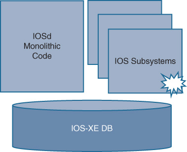
Although individual processes within IOS XE have to be rewritten or altered to operate as separate subsystems (which takes time to do), IOS XE provides a strong foundation upon which various pieces of networking code can be altered—in an evolutionary way—to adopt these subsystem capabilities. As the evolution of IOS XE progresses, more and more subsystems can be broken out from the IOSd monolithic code base, allowing these functions—and the network managers that use these capabilities—to leverage the benefits of the modularized subsystem approach.
An additional benefit of the separation of code into subsystems is that these subsystems are equipped with well-defined interfaces, thus allowing alterations to areas of the code base to have less chance of disruption to other code areas. Over time, this leads to a more stable code base, and one that can be more rapidly altered to meet new network needs.
IOS XE Database
Previously in IOS, all the various pieces of code that might execute in IOS retained their own configuration and operational state in their private and separate memory areas. For example, OSPF, EIGRP, BGP, and Spanning Tree each retain their own separate sets of operational data, with no common method being used for data storage. Although this met the needs as they existed in the network, it did not allow for retention of this data across (for example) a process restart, meaning that this data was lost and had to be relearned when the process restarted.
In a device environment that hosts modularized subsystem processes, a more advanced capability was needed for process state retention, as well as data exchange between independent processes. This was the rationale behind the creation of the IOS XE Database function, which is illustrated in Figure 8-8.
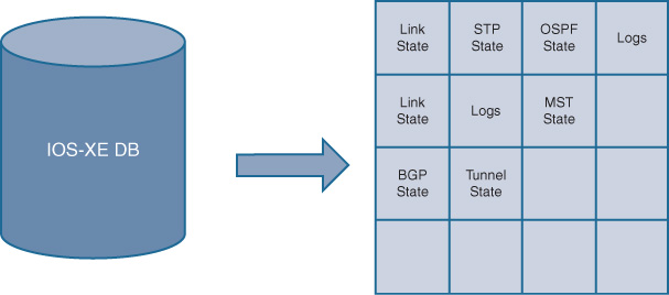
Various processes running under IOS XE are able to store their operational state and configuration data within the IOS XE Database, allowing it to be retained across process restarts, as well as to be more readily exchanged with, and examined by, other IOS XE processes operating within the platform. Although processes have to be recoded or altered to use the database functionality provided by IOS XE, this provides a strong foundational component for the evolution and use of next-generation networking capabilities—a key focus of IOS XE.
The decoupling of code and data provided by the IOS XE Database provides several key advantages: namely, the ability to provide higher application uptime, quicker recovery from network outages (because the operating state prior to the outage can more readily be recovered from the database rather than having to be relearned via the network), and an overall improvement in network reconvergence times (a key attribute in the modern network deployment, where so many business-critical functions all rely on the underlying network and its operational characteristics).
The use of the database approach in IOS XE also allows much easier access to common data models, such as those provided by YANG, accessed by open and programmable interfaces such as NETCONF and RESTCONF. This is illustrated in Figure 8-9.
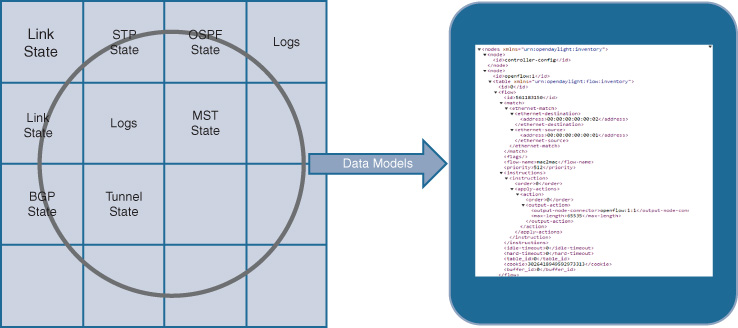
By retaining data from various processes in a common database structure, this information is more readily extracted and used by various data-modeling approaches and access methods. The use of these approaches and data models is explored further in Chapter 13 and is further illustrated in Figure 8-10.
By leveraging a common database for storage of configuration and operational states, a more robust environment is provided both for making this data available to external functions running off-box (via standardized interfaces and data models) and for use by the container-based application hosting framework created by IOS XE—the third key architectural pillar provided by the IOS XE environment.
Container Framework and Application Hosting
Today, the network is the key enabler of many functions by the modern enterprise. Network gear, including switches and routers, are located at key points of information flow within, and between, enterprise networks. As such, there is often a desire to run additional functions on a given piece of network gear.
In the past, this capability was very limited, or even nonexistent. Older versions of IOS (prior to IOS XE) ran, as mentioned previously, as a single piece of monolithic code which directly interfaced with the underlying network hardware. While this provided simplicity, and utilized those hardware resources very concisely (an important consideration when such resources were very scarce), it did not provide any way to “co-host” other application on the same piece of network hardware. The very infrastructure of IOS did not previously allow for this.
Starting with the earliest versions of IOS XE, Cisco began to provide the ability to host certain designated functions on a router or switch platform, alongside IOSd itself. These included WCM—the Wireless Control Module leveraged by Converged Access deployments—as well as Wireshark, leveraged to provide on-box packet-level capture of traffic flows transiting the network node.
While functional, a desire existed to broaden this capability to encompass more use cases. Thus was born the capability to provide a more general framework to support containerized applications, co-hosted on an IOS XE platform. This is illustrated in Figure 8-11.
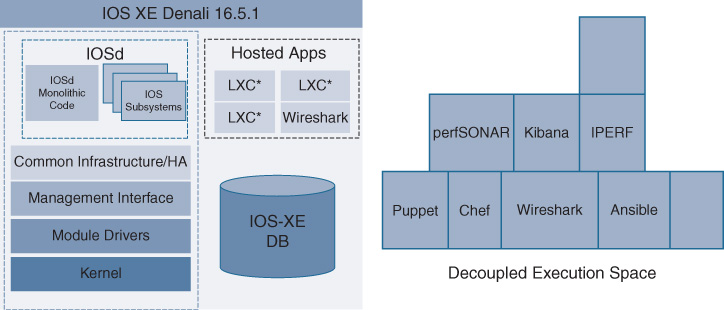
By providing a decoupled execution space in which containerized apps can operate, the framework to host applications on a given IOS XE switch or router platform is provided.
Resources (storage space, memory, processing CPU cycles, etc.) on such a platform still need to be carefully husbanded in order to preserve network stability (after all, this same base of resources is operating the network as well). Accordingly, the apps to be containerized and operated on the network platform involved must be selected on the basis of working within the constraints inherent to a network-based platform. The app-hosting framework provided by Cisco IOS XE allows for the provision of containerized applications which can operate on an IOS XE platform, leading to many possible exciting future capabilities for deployment and use within the network. These might include application performance monitoring, network analysis, and other unique examples of network-integrated functionality.
Cisco IOS XE: Bringing It All Together
They say that the whole is often greater than the sum of its parts. This is certainly true of IOS XE.
One of the major benefits of, and goals for, IOS XE is the capability called Run Any Feature Anywhere (RAFA). Because IOS XE is designed to be utilized at many points in the enterprise network, and across many platforms (switches, routers, etc.), the ability exists to create a feature once and then deploy it at many locations, and across multiple platforms, within the enterprise network.
When intersected with the capability, as described in Chapter 7, “Hardware Innovations,” of using the same flexible, programmable ASIC hardware (for example, UADP, Unified Access Data Plane) across multiple platforms, this creates the ability to achieve much faster deployment times for new features across platforms, enabling greater feature velocity as well as feature consistency, without the need to touch platform-independent items of code when bringing new capabilities onto a given platform. This is illustrated in Figure 8-12.
With this capability, only the platform-dependent portions of the code base need to be modified as a function is made available across multiple platforms. And because IOS XE software, and flexible hardware forwarding elements such as UADP and QuantumFlow Processor (QFP), are more and more common across multiple platforms using IOS XE, the ability to provide functionality more broadly, and more quickly, to the marketplace becomes very apparent—and to do so in a more operationally consistent manner.
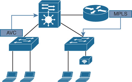
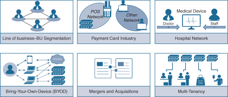
Take, for example, the function of Multiprotocol Label Switching (MPLS). MPLS has long been deployed in service provider networks to provide network segmentation, and is increasingly deployed in sophisticated enterprise networks that also require separation of communications across network segments within the enterprise, at scale. Some of the most common use cases for MPLS within the enterprise are illustrated in Figure 8-13.
In the past, MPLS platform-independent (PI) code was created as part of a base set of IOS functionality, but it had to be adapted not only to every platform to couple it to that platform’s unique data plane hardware (which may or may not even have the capability to support MPLS in hardware), but also to that platform’s unique IOS train and infrastructure set. The net result of this is that promulgating a function such as MPLS across a wide set of enterprise devices (best case) took a long time, or (worst case) was limited to only a subset of network devices, due to hardware limitations within the device (for example, the Catalyst 6500/6800 supports MPLS in hardware using the EARL7/EARL8 ASIC set, but the Catalyst 4500-E/4500-X using the K10 chipset, or the Catalyst 3750 and older switches, cannot).
Now, by having both a common ASIC set across enterprise platforms (UADP for switching, QFP for routing) and a common set of IOS XE software, the implementation and broad deployment of a given feature set is far more rapid than in the past. This in turn allows customers to use these features and functionality more rapidly in their networks to solve real business problems and drive competitive advantage. In addition, the familiarity and continuity provided by the IOS experience means that staffing levels and expertise are better leveraged as the network grows and expands—thus helping to control long-term costs, and at the same time supporting an increased pace of innovation.
While there will always be platform-level differences driven by scale, market focus, and other considerations, the ability to provide greater network design and deployment consistency, driven by IOS XE, is a key advantage for organizations large and small.
Several important new innovations in network protocols are examined in Chapter 9, “Protocol Innovations.” How those protocols in turn serve as the basis for powerful new solutions are explored in Chapter 19, “Cisco DNA Software-Defined Access.” As we explore further, we will consistently see the power of IOS XE, combined with Cisco’s flexible hardware infrastructure, in action.
Cisco IOS XE: Simplification with a Single Release Train
One of the major goals of IOS XE is to reduce the number of IOS release trains, and releases, with which customers have to contend. By creating a common code base to be leveraged across multiple platforms, IOS XE allows for simplified network operation and use by providing the following:
Simplified and more consistent network administration
Simplified and more consistent software lifecycle management
The same CLI across multiple platforms for common features
The ability to leverage platform capabilities in a consistent manner
Within hardware platforms that share many common components, this can go so far as the same binary image running across multiple platforms. For example, with the Catalyst 9000 Series switches, the exact same binary image (not just the same software version, but the exact same binary image) is deployed across the Catalyst 9300, 9400, and 9500 switch platforms—the first time ever that a single image was used across a Cisco stackable access switch, a modular access switch, and a fixed-configuration core/aggregation switch.
This ability to use the exact same binary image across multiple platforms makes it possible to qualify the image once (a process undertaken by many larger enterprise organizations, and one which can consume a great deal of time and resources for image qualification), and then reuse this image, and the capabilities it provides, across multiple places in the enterprise network. This reduces the time and effort required for such image and function qualification, and increases the speed with which enterprises test, deploy, and use sophisticated network functions across multiple platforms.
Cisco IOS XE: Software Maintenance Upgrades
Another example of the flexibility provided by IOS XE is the new capability known as Software Maintenance Upgrades, or SMUs.
SMUs are pieces of deployable code, typically small in size, that are intended as urgent point fixes for particular issues that may arise, allowing for an expedited delivery of that fix to customers in case of challenges that might include network-down or potentially revenue-affecting scenarios.
In the past, when a critical issue arose, it was often possible to address this via an updated version of software. However, that fix would have to be embedded within a larger binary image, one which would often have the fix for that particular issue, but additional code as well (addressing particular issues that the deployment involved may not have faced, or even code that implemented new features or capabilities). The enterprise thus might have had to accept, in an expedited fashion, a new software version to gain access to the fix needed—and accept everything else that came with that new release, including perhaps even bugs not present in their previous release. In any case, to access the fix to relieve the issue it was experiencing, the enterprise had to accept a new software image that it may not have had time to properly qualify.
SMUs are designed to address this situation. In particular, SMUs are designed to be
Quick to deploy: SMUs are able to deliver point fixes much faster than by waiting for a new IOS XE release
Effective: SMUs do not require an entire binary IOS XE code upgrade
Focused: SMUs target the particular area of code that has the issue, and no other
In effect, SMUs are like a medication, in that:
They address the issue involved effectively.
In theory, there is no limit to the number you can take.
In practice, you want to be selective when employing SMUs.
The Issue with Software Upgrades
In general, software upgrades are challenging for enterprise networks, across several dimensions of operation. These challenges include the following:
Cost: Network software upgrades are expensive to plan, test, and deploy. Properly testing code prior to deployment is challenging, and many enterprises (especially smaller ones) lack the resources to do this effectively (as this might include the creation and use of a separate lab environment, the need to provide simulated application and user loads, etc.). In addition, each device upgrade causes a network outage as it is deployed, and so the rollout of the code upgrade must be carefully planned to minimize impact to the production network.
Time: Many organizations today are faced with the challenge of doing more with less, or at best with the same amount of resources. Thus, the personnel required to maintain the network must also be the ones to upgrade it. The reduced number of staff available to many organizations today makes software upgrades and rollouts even more challenging to plan and execute. In addition, the network outages (or potential for them) associated with large, monolithic software upgrades often make a physical, onsite presence required, or at least desirable, during the upgrade process, at least at critical nodes within the network.
Scope: As mentioned previously, new code typically requires a level of certification and analysis (often known as a “bug scrub”). The greater the potential scope of impact for a given code upgrade, the greater the need for such analysis becomes.
The use of SMUs with IOS XE can assist in addressing these points, by providing focused “point fixes” which reduce the cost, time, and scope of a given software fix deployment.
Types of SMUs—Cold, and Hot
SMUs with IOS XE come in two flavors: cold and hot.
Cold patches: The simplest type of SMU, these are small pieces of code that are loaded onto an IOS XE platform, integrated with the existing release, and then require a reload of the device software to activate them. However, unlike a code upgrade to the entire box, the SMU in this case only affects the particular focused code that it patches—the larger IOS release running on the platform is unaltered (and thus, the operation and use of non-patched portions of the code is not affected). Due to the nature of how they are applied (device restart), cold SMUs are traffic-affecting. As of this writing, all SMUs available for IOS XE are of the cold variety.
Hot patches: These allow for the “hot” restart of a patched process within IOS XE, and do not require a device reload. Such processes also typically leverage the database capability of IOS XE to checkpoint their state prior to such a restart (if applicable), thus allowing a faster recovery once the newly patched process comes back up. As of this writing, no hot SMUs are yet available for IOS XE. However, the architecture of the system allows for this capability to be delivered in the future.
Installing a SMU
Installation and activation of SMUs follows a three-step process, as detailed in Figure 8-14.
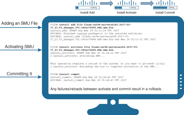
The steps are as follows:
Step 1. Add the SMU file: This basically consists of loading the SMU (delivered as a small, packaged binary file) onto the platform in the normal way (say, FTP or TFTP), and running the install add command to point to it.
Step 2. Activate the SMU: Running the install activate command activates the SMU and (in the case of a cold SMU) performs a device reload. When the device reloads, the new SMU becomes activated, integrated with the IOS XE code running on the device.
Step 3. Commit the SMU: Running the install commit command is used to commit, and keep, the patched SMU on the device. In the event of any failures between the activate and commit commands, an automatic rollback backs the SMU out of operation, thus providing a “safety net” for the deployment.
Benefits of SMUs
Even with the use of cold SMUs that require a device reload, the actual code that is targeted and patched to fix the particular point issue involved is much smaller than the amount of new code that an enterprise typically has to accept with a full IOS image upgrade. This makes SMUs—even cold ones—of significant benefit to enterprises, because they reduce the time, and the risk, associated with validating and deploying a code upgrade for a given point issue.
With the advent of hot SMU deployment capability in the future, this functionality will become even more valuable to network managers, because they will be able to deploy fixes for selected point-fix issues without even having to do a device reload.
Cisco plans to prioritize the availability of SMU point fixes for the most critical issues, based on the technical feasibility of delivering a SMU patch for a particular problem, a risk analysis of the impact of the issue involved in customer networks, and the benefits to customers from delivering such a method for a particular point fix versus including the fix in a broader Cisco IOS XE release vehicle. Although some additional complexity may exist in terms of keeping track of which SMUs a given device has installed over time, this is likely to be outweighed by the flexibility that the IOS XE SMU infrastructure provides. The use of SMUs does not eliminate the need for integrating code fixes into new IOS XE releases, which will continue to happen, but SMUs do allow for a new, innovative method of “point-fix” delivery for critical code issues in IOS XE—an important factor in the always-on, always-operational network environment of today, and tomorrow.
Cisco IOS XE: Platform Support
Cisco IOS XE is available across multiple switch and router platforms, including many of the most common platforms deployed in enterprise networks today. These include:
Cisco Catalyst 3850 and 3650
Cisco ASR 1000 platforms
Cisco ISR 4000 platforms
Cisco CSR (Cloud Services Router)
Cisco Catalyst 9300—stackable access switch
Cisco Catalyst 9400—modular access switch
Cisco Catalyst 9500—fixed aggregation/core switch
The timeline of IOS XE releases across the platforms is summarized in Figure 8-15.
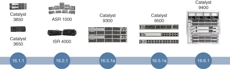
In particular, note that all of the Catalyst 9300, 9400, and 9500 platforms shown in Figure 8-15 use the exact same binary image, further simplifying the qualification, testing, and deployment of IOS XE across an end-to-end Catalyst 9000–based switched infrastructure, and marking a significant departure from the past in which multiple different software images, with disparate capabilities, might need to be deployed across the various switched infrastructure layers within a campus or branch network infrastructure.
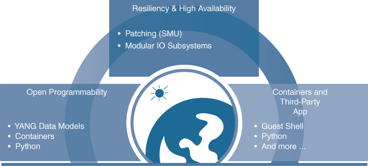
Cisco IOS XE: Summary
In summary, IOS XE provides a strong foundation upon which to build the next generation of enterprise networks: a modern operating system for a new era of networking. Figure 8-16 summarizes the benefits that IOS XE provides, including better resiliency and high availability through modular subsystems and patchability, open programmability via standardized YANG data models and access methods such as NETCONF and RESTCONF, and the ability to host containerized apps.
As Cisco and its customers embark on the evolution of enterprise network deployments with Cisco DNA—an evolution explored throughout this book—having a solid base upon which to build is critical. Cisco IOS XE provides that base, and when combined with Cisco’s flexible, programmable hardware infrastructure, provides an unmatched capability to take on the most significant network challenges of today, and tomorrow, enabling a new set of capabilities for the next generation of network deployments and solutions. Some of these solutions are explored later in this book, such as critical new capabilities like Cisco Software-Defined Access, which leverage Cisco IOS XE and Cisco’s programmable hardware to the hilt.
Now that we have reviewed some of the latest innovations with IOS XE, let’s see some of the other areas where Cisco is driving important innovations for enterprise network deployments. Let’s continue by examining an area of concern to many network administrators today, the security of the devices that make up their networks.
Protecting Platforms and Networks: Trustworthy Systems
With so much riding on the network infrastructure—often, the entire operation of an organization—it is important to pay close attention to protecting that infrastructure. IOS XE, along with other elements in Cisco’s software and hardware portfolio, provides this via a mechanism known as trustworthy systems.
There are many elements that must be considered when properly securing a network infrastructure. Some common ones are firewalls, encryption, and ACLs. These are vitally important, with the majority of them focused on securing the data plane for data in flight—after all, that’s what a network does, move data from point A to point B, and securing the data involved in between those points is critical.
However, in addition, an equally critical, yet often overlooked, area is the protection of the network device itself. It is vital to protect the integrity of the network platform from unwanted interference and outright attacks. Unless the network device is known to be secure, how can the network it supports be secure? Good security needs to start at the device foundation. This is the bedrock of the concept of the Cisco trustworthy systems initiative.
Trustworthy Systems: An Overview
Cisco trustworthy systems are designed to provide checks and balances that help validate network device platform integrity and provide alerts of any out-of-profile conditions and limit their impact.
Figure 8-17 outlines some of the capabilities that are intended to be addressed by Cisco trustworthy systems focused around platform integrity.

Possible Attacks: IOS Modifications
First, let’s examine some of the potential attacks that could be launched against a network device. For now, ignore attacks focused on bringing down the network, such as denial-of-service (DoS) attacks, as they are more well known, as are the mitigation techniques used to defeat them. Instead, let’s focus on attacks that attempt to compromise the integrity of the network device platform itself.
Over the years, various attacks have been observed that attempt to modify the IOS software running on a device, with the intention of being able to compromise that device, or even take over the operation of the device, modify some aspect of the device’s operation, or extract data from it.
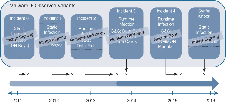
Figure 8-18 outlines some of these attacks, along with a rough timeline corresponding to when these have been observed “in the wild.”
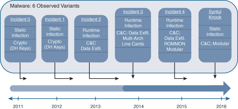
Ranging across static and runtime infections, these attempts to inject malware into Cisco network devices tried to install command and control (C&C) systems, exfiltrate critical data, and compromise or alter crypto keys used for data privacy. All of these types of attacks are of great concern to the network administrator. Perhaps of even greater concern is the next attack—the one that nobody knows about yet because it has not yet been invented.
Attack Mitigation with Trustworthy Systems
What can be done to address these various types of attacks, and to help secure the network infrastructure and the various devices within it? This is where the Cisco trustworthy systems initiative comes in.
Cisco created the concept of trustworthy systems as a multilayered defense against such attacks on network device integrity. Accordingly, there are several areas of defense against such attacks, and several techniques and capabilities that are employed as part of the Trustworthy Systems approach. These are outlined in Figure 8-19, which also indicates which defense method is most appropriate at addressing which attack vector.
Each of the attack mitigation techniques, and explanations of the attack vectors that they are designed to contain are examined next.
Defense: Image Validation and Signing
Perhaps the easiest set of techniques to understand is image validation and signing. Every Cisco IOS image that employs image validation protection (including all Cisco IOS XE images) has an MD5 hash from the binary contents of the image provided by Cisco, which allows for the comparison of this MD5 hash as computed on the device to the corresponding MD5 value as posted on the Cisco.com website. Any tampering with the image (that is, altering the binary image to insert unwanted code) causes the MD5 hash used to sign the image to fail to validate, thus alerting the network manager that the image involved was compromised, and to take corrective action. As of 2015, Cisco uses SHA-512 hashes to validate images posted to Cisco.com.
In addition, some platforms and software versions also support digitally signed images, providing an ability to validate not only that the Cisco IOS image was not tampered with, but that the image originates from a trusted source (because it is signed with Cisco’s private key, and verified with Cisco’s public key, using asymmetric cryptography).
As shown in Figure 8-19, image signing is effective at defeating a number of attack vectors. Many static device infections or attack attempts can be detected, and defeated, with this widely deployed method. Image signing is thus an important foundational element of device-level security and validation. However, this does not by itself address all of the possible attack vectors that may be targeted at a network device.
Defense: Runtime Defenses
Once a network device boots up and is operating in the network, it may sometimes be possible to insert code into the device during runtime that could cause unwanted access or control of the device. For example, this may be done via a buffer overflow attack or similar attack vector, where advantage can be taken to insert code into a memory space in the device adjacent to a buffer space for traffic, by overflowing this buffer with an unexpectedly large or long data entry that may not be properly range-checked by the software on the device involved.
This technique is not limited to network devices, and has been used across many different device types and disparate operating systems for the insertion of malicious code.
What can be done in a networking device, such as a switch, to address such an attack?
An important capability implemented by some Cisco platforms, such as the Catalyst 9000 Series switches, is Address Space Layout Randomization (ASLR). ASLR randomizes the layout of code across the memory space of a device, making traditional attack techniques such as buffer overflow attacks much harder to execute because the same code is not laid down in the same place in memory every time. This is an example of how runtime defenses help defeat attempts to subvert a given network device.
Defense: Secure Boot
Despite all other attempts made to protect the integrity of the network device, most or all of them may be rendered invalid if control is gained by the attacker over the boot sequence of the device itself. If the boot process of the network device is subverted, many or all of the other checks that the network device might perform to verify the device’s integrity can be defeated, because control early enough in the boot sequence effectively provides “root” control of the device—and does so in a way that is not easily detected or defeated. Even swapping out the software image on a device does not defeat such an attack if it occurs early enough in the boot sequence.
Protecting the integrity of the boot sequence is critical to secure device operation. This is the impetus behind Cisco’s development of the Secure Boot process, and the hardware underpinnings that enable it. Let’s proceed to understand Secure Boot as part of the Cisco trustworthy systems set of capabilities.
Understanding Boot Sequence Attacks
You need to understand how a network device boots up in order to understand the measures that need to be taken to protect this process.
Figure 8-20 shows, at a high level, what happens when a network device, such as a switch or router, boots up, and serves as a base to understand what means an attacker might use to subvert that boot sequence.
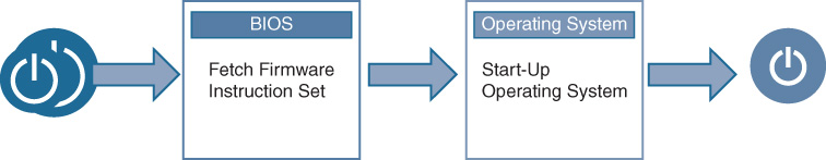
Basically, when powered on or restarted, a network device activates its BIOS (Basic Input/Output System) code, a process that loads up the operating system (typically from local flash storage). The OS begins to enable the operation of the network device—data plane, control plane, and management plane functions.
An attacker can compromise this process by changing various parameters—the boot interface or device, bypassing the integrity checks on the code, or inserting persistent code into the device. While the OS integrity checks help to validate whether the OS image was tampered with, what about the integrity of the BIOS itself? What if an attacker managed to modify the BIOS, or bypass it? In other words, who guards the guardians?
Protecting Device Integrity from the Ground Up with Secure Boot
This is where Cisco Secure Boot comes in—by creating an immutable (nonmodifiable) hardware-based trust-anchor in a network device, one whose integrity can be cryptographically verified, and creating a “chain of trust” that allows the integrity of a network device to be ensured to a far greater degree than was possible in the past.
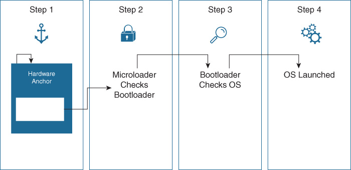
The process involved in Cisco Secure Boot is outlined in Figure 8-21.
Secure Boot provides the following important items to check for software authenticity:
Only authentic signed Cisco software images are able to boot up on a Cisco platform leveraging Secure Boot.
The boot process stops if any step fails to authenticate.
The Cisco IOS command show software authenticity is used to illustrate the results of the secure boot process.
Verifying results of the boot process also relies on the hardware trust anchor, TAm. This is a tamperproof piece of hardware that is built into the Cisco network device and implements an anti-tamper and anti-theft chip design. The hardware trust anchor uses built-in crypto in the form of a secure X.509 certificate, creating an immutable identity. This also serves as a secure repository for certificates and objects used for device authentication, and provides a certifiable entropy source for random number generation.
The purpose of the trust anchor as part of the Secure Boot process is to instantiate and start the microloader. Because this microloader originates in tamper-proof hardware, it is not modifiable, and is cryptographically verified for integrity. The microloader, being very small and simple, then loads up the bootloader, verifying its integrity. The bootloader loads up the main software image for the platform, again verifying the integrity of that image.
Because the trust at each stage in this process is based in trust on the prior stage, beginning with a hardware-based, non-modifiable, cryptographically secure microloader from the Trust Anchor module, a chain of trust is established that renders the entire boot process secure. If any stage in the boot process fails to verify, the boot process stops at that point, preventing the compromised network device from gaining access to, or becoming part of, the enterprise network involved.
Secure Boot is a critical element in creating a secure and tamper-resistant network environment. Many modern Cisco devices, such as the Catalyst 9000 Series switches, provide a hardware-based Trust Anchor module as the basis for the Secure Boot system that they offer.
Ensuring Device Identity with the Secure Unique Device Identifier
An additional important integrity check on many networks is ensuring that the devices are identified in a secure way and are well known to the network and to the network administrator and his or her network monitoring systems. For example, if an attacker swaps out a known-good network device with one that was modified to subvert its operation, or inserts a compromised network device into the network without detection, that device could be used to compromise network traffic flows. Detecting and defeating such attacks is also an important part of a trustworthy systems deployment.
Protecting against such an insertion of an unwanted network device is done by verifying the network device’s Secure Unique Device Identifier (SUDI). The SUDI is a hardware-based cryptographic identifier that is embedded into the device during manufacturing and serves as a unique “fingerprint” for the device.
By inspecting the SUDI of the device, and matching that against devices expected to be (and authorized) in the network, the network administrator can quickly identify rogue devices if they are attached to the network, and block such devices from participating in the network infrastructure.
The SUDI supports multiple functions:
Provides a tamperproof ID for the device
Allows for authentication of connections with the device using the SUDI credential
Binds the hardware identity to a key pair in a cryptographically secure X.509 certificate PID during manufacturing
Cisco Secure Boot and Trust Anchor Module: Validating the Integrity of Software, Followed by Hardware
Now, let’s bring it all together to better understand the Secure Boot process, as well as sum up the Cisco trustworthy systems initiative overall.
Figure 8-22 illustrates how Cisco Secure Boot and the Cisco Trust Anchor module operate together to ensure the integrity of the network device, from initial power-on, through boot-up, and verifying the integrity of the network hardware.
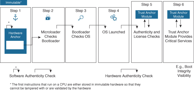
Taken together with image signing and runtime defenses, this combination forms a powerful combination to assist in defeating many attacks that aim to subvert network devices. The Cisco trustworthy systems initiative, and the capabilities it encompasses, is a critical element in securing the integrity of the network devices, and is an important element in any organization’s end-to-end security strategy.
Given the importance of the information flowing across networks in today’s organizations, such protection of the integrity of the network devices that make up the network infrastructure is of vital importance. Cisco trustworthy systems helps validate such device—and network—integrity.
The Move to Intuitive Networking
We’ve spent a lot of time in this chapter examining Cisco IOS XE, which is appropriate because Cisco IOS is the most widely deployed network operating system in the world, and IOS XE is the next stage in the evolution of this critical software asset. However, there are many other areas of software innovation that Cisco is also driving. These include both the move toward intuitive network infrastructures and the move toward rapid, automated, programmatic change within network deployments using network controllers.
Cisco began the move toward the use of network controllers within the infrastructure a few years back, with the creation and deployment of the Cisco Application Policy Infrastructure Controller Enterprise Module (APIC-EM). Not the catchiest of names, perhaps, but what it may have lacked in naming it made up for in functionality. APIC-EM was the first true enterprise-class controller for Cisco network deployments, created with the goal of being an application platform that provided network discovery, automated the deployment of critical functions within the enterprise provided network, and allowed for simplified network troubleshooting.
As time moved forward, APIC-EM gave way to the next generation of intuitive networking—namely Cisco DNA Center. Building upon the initial goals of APIC-EM in terms of network discovery and automation, Cisco DNA Center also added the capability to provide Assurance, the ability to continuously monitor the underlying network infrastructure, report on errors or out-of-profile network conditions that might require a network operator’s attention, and suggest the appropriate course of action to correct the issue.
The overall capabilities of Cisco DNA Center are outlined in Figure 8-23.
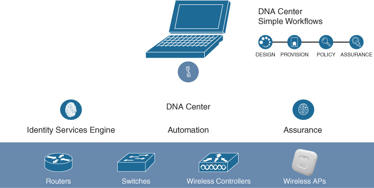
The capabilities of Cisco DNA Center are examined in much more detail in the following chapters covering Network Automation and Assurance. For now, suffice it to say that Cisco DNA Center and the movement that it embodies toward truly intuitive networking are key cornerstones of future network deployments, allowing the capabilities delivered by Cisco IOS XE, Cisco’s flexible hardware platforms, and solutions such as Software-Defined Access to be realized, and maximized, in enterprise network deployments in a simple and scalable manner.
Summary
This chapter explored the evolution of networking software, and the various “planes of operation” in a network—data plane, control plane, and management plane—and how these have evolved over time. It also explored the evolution of Cisco IOS, the most popular and widely deployed networking software in the world, and discussed Cisco IOS XE in detail. You read how IOS XE, in conjunction with the Cisco flexible, programmable hardware components (discussed in the preceding chapter), evolved to address the networking challenges of today, and tomorrow.
This chapter also described some of the attacks against network devices and reviewed advanced techniques deployed in modern network devices to detect, and defeat, such attacks using Cisco trustworthy systems.
Finally, this chapter discussed how networks are evolving with controller-based approaches and the future of intuitive networking with network automation and assurance capabilities, using Cisco DNA Center.
Going forward, let’s explore how the protocols used to construct networks are also evolving as networking continues to progress. This evolution of network protocols, and the new innovations being driven there, is the subject of the next chapter.
Further Reading
Cisco IOS XE At-A-Glance: https://www.cisco.com/c/dam/en/us/products/collateral/ios-nx-os-software/ios-xe/nb-09-ios-xe-secure-open-flex-aag-cte-en.pdf
Cisco Trustworthy Systems FAQ: https://www.cisco.com/c/dam/en_us/about/doing_business/trust-center/docs/cisco-trustworthy-systems-faq.pdf.