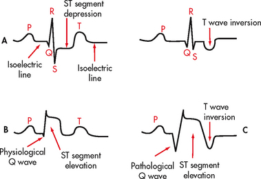
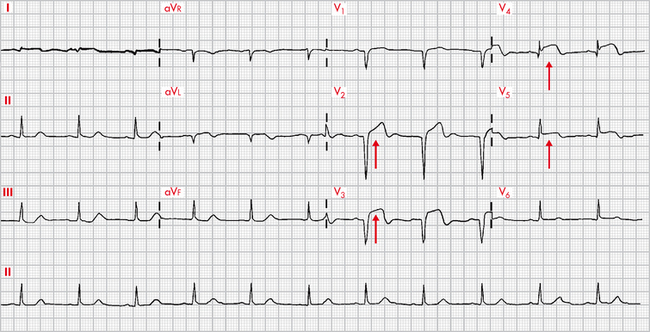
Chapter 35 NURSING MANAGEMENT: ECG monitoring and arrhythmias
1. Describe the nursing management of patients requiring continuous electrocardiographic (ECG) monitoring.
2. Identify the clinical characteristics and ECG patterns of normal sinus rhythm, common arrhythmias and acute coronary syndrome (ACS).
3. Describe the nursing and collaborative management of patients with common arrhythmias and ECG changes associated with ACS.
4. Differentiate between defibrillation and cardioversion, identifying indications for their use and physiological effects of each.
5. Describe the management of patients with temporary and permanent pacemakers.
6. Describe the management of patients with implantable cardioverter–defibrillators.
7. Explain the management of patients undergoing electrophysiological testing and radiofrequency catheter ablation therapy.
automatic external defibrillator (AED)
premature atrial contraction (PAC)
Rhythm identification and treatment
The ability to recognise normal and abnormal cardiac rhythms is an essential skill for the nurse. Cardiac monitoring is now used in a wide range of hospital, clinic and home settings. Prompt assessment of arrhythmias (abnormal cardiac rhythms) and the patient’s response to the rhythm is critical. This chapter describes basic principles of electrocardiogram (ECG) monitoring and recognition of common arrhythmias, as well as ECG changes that are associated with acute coronary syndrome (ACS). For more detailed information on ECG interpretation, refer to dedicated texts on this topic.1–3
CONDUCTION SYSTEM
Four properties of cardiac cells enable the conduction system to initiate an electrical impulse, which is transmitted through the cardiac tissue, stimulating muscle contraction (see Table 35-1). The conduction system of the heart is made up of specialised neuromuscular tissue located throughout the heart (see Fig 31-5). A normal cardiac impulse begins in the sinoatrial (SA) node in the upper right atrium. It is transmitted over the atrial myocardium via Bachmann’s bundle and internodal pathways causing atrial contraction. The impulse then travels to the atrioventricular (AV) node through the bundle of His and down the left and right bundle branches, ending in the Purkinje fibres, which transmit the impulse to the ventricles.
TABLE 35-1 Properties of cardiac cells
| Automaticity | Ability to initiate an impulse spontaneously and continuously |
| Excitability | Ability to be electrically stimulated |
| Conductivity | Ability to transmit an impulse along a membrane in an orderly manner |
| Contractility | Ability to respond mechanically to an impulse |
Conduction to the point just before the impulse leaves the Purkinje fibres takes place within the time of the PR interval of the ECG. When the impulse emerges from the Purkinje fibres, ventricular depolarisation occurs, producing mechanical contraction of the ventricles and the QRS complex on the ECG. The electrical activity of the heart is illustrated in Figure 31-6.
NERVOUS CONTROL OF THE HEART
The autonomic nervous system plays an important role in the rate of impulse formation, the speed of conduction and the strength of cardiac contraction. The components of the autonomic nervous system that affect the heart are the right and left vagus nerve fibres of the parasympathetic nervous system and fibres of the sympathetic nervous system. (The nervous system is described in Ch 55.)
Stimulation of the vagus nerve causes a decreased rate of firing of the SA node, slowed impulse conduction of the AV node and decreased force of cardiac muscle contraction. Stimulation of the sympathetic nerves that supply the heart has essentially the opposite effect on the heart.4
ECG MONITORING
The ECG is a graphic tracing of the electrical impulses produced in the heart. The waveforms on the ECG are produced by the movement of charged ions across the membranes of myocardial cells, representing depolarisation and repolarisation. The membrane of a cardiac cell is semipermeable, and it is the movement of charged ions across these cell membranes that causes the heart muscle to respond. A high concentration of sodium and a low concentration of potassium are maintained outside the cell. The inside of the cell, when at rest or in the polarised state, is negative compared with the outside. When a cell or groups of cells are stimulated, each cell membrane changes its permeability and allows sodium to move rapidly into the cell, making the inside of the cell positive compared with the outside (depolarisation). A slower movement of ions across the membrane restores the cell to the polarised state, which is called repolarisation.1,3
In the rest of the body, the action potential (AP) results from the opening and closing of the sodium and potassium channels (see Fig 35-1). Since there are only two channels involved, the AP produced is incredibly swift, taking just a couple of milliseconds; the effect of one immediately follows the other. In the case of the cardiac AP (i.e. the AP that occurs in the cells of the heart), three channels are involved: sodium, potassium and calcium. As with a normal AP, the depolarisation to the threshold leads to the opening of the sodium channels, causing a rapid upstroke. At a membrane potential of about −30 to −40 mV, the calcium channels open. The entry of calcium through these channels maintains the cell’s depolarisation, so instead of lasting just a couple of milliseconds, the cardiac AP lasts about 300 milliseconds. Eventually, the potassium channels open sufficiently to cause repolarisation and the membrane potential returns to the resting state. In Figure 35-2, the phases of the cardiac AP are as follows: phase 0 is the upstroke of rapid depolarisation; phases 1, 2 and 3 represent repolarisation; and phase 4 is a polarised state.1 Antiarrhythmia drugs have a direct effect on the various phases of the action potential.1 When antiarrhythmia drugs are used in a clinical setting, an understanding of the ionic shifts in the cardiac cell and the AP mechanism is important. (AP is also discussed in Chs 31 and 55.)
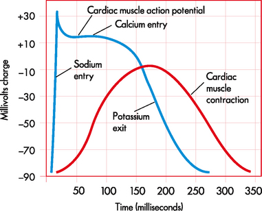
Figure 35-1 Comparison between the cardiac muscle action potential and cardiac muscle contraction.
Source: Based on Patton KT, Thibodeau GA. Anatomy and physiology. 7th edn. St Louis: Mosby; 2010.

Figure 35-2 Phases of the cardiac action potential. The electrical potential, measured in millivolts (mV), is indicated along the vertical axis of the graph. Time, measured in seconds, is indicated along the horizontal axis. There are five phases of the action potential, labelled as phase 0 through to phase 4. Each phase represents a particular electrical event or combination of electrical events. Phase 0 is the upstroke of rapid depolarisation and corresponds with ventricular contraction. Phases 1, 2 and 3 represent repolarisation. Phase 4 is known as complete repolarisation (or the polarised state) and corresponds to diastole. TP, threshold membrane potential; RP, resting membrane potential.
Conventionally, there are 12 recording leads in the ECG. Six of the 12 leads measure electrical forces in the frontal plane (leads I, II, III, aVR, aVL and aVF) (see Fig 35-3); the remaining six (V1–V6) measure electrical forces in the horizontal plane (praecordial leads). The 12-lead ECG may show changes that are indicative of structural changes or damage such as ischaemia, infarction, enlarged cardiac chambers, electrolyte imbalance or drug toxicity.1 Obtaining 12 views of the heart is also helpful in the assessment of arrhythmias. An example of a normal 12-lead ECG appears in Figure 35-4.

Figure 35-3 A, Limb leads I, II and III. Leads are located on the extremities. Illustrated are the angles from which these leads view the heart. B, Lead placement for limb leads aVR, aVL and aVF. These unipolar leads use the centre of the heart as their negative electrode. C, Lead placement for the chest electrodes: V1, fourth intercostal space at the right sternal border; V2, fourth intercostal space at the left sternal border; V3, halfway between V2 and V4; V4, fifth intercostal space at the left midclavicular line; V5, anterior axillary line and same horizontal level as V4; V6, midaxillary line and same horizontal level as V4.
When a patient’s ECG is being continuously monitored, 1 to 12 ECG leads may be used. The most common leads selected are leads II, MCL1 and V1 (see Fig 35-5). Current recommendations state that monitoring leads should be selected based on the patient’s clinical situation.5
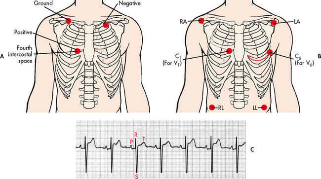
Figure 35-5 A, Lead placement for MCL1 using a three-lead system. B, Lead placement for V1 or V6 using a five-lead system. C, Typical electrocardiogram tracing in lead MCL1. C, chest; LA, left arm; LL, left leg; MCL, modified chest lead; RA, right arm; RL, right leg.
The ECG can be visualised continuously on a monitor oscilloscope. A recording of the ECG (i.e. rhythm strip) is obtained on ECG paper attached to the monitor. This provides documentation of the patient’s rhythm. It also allows measurement of complexes and intervals and assessment of arrhythmias.
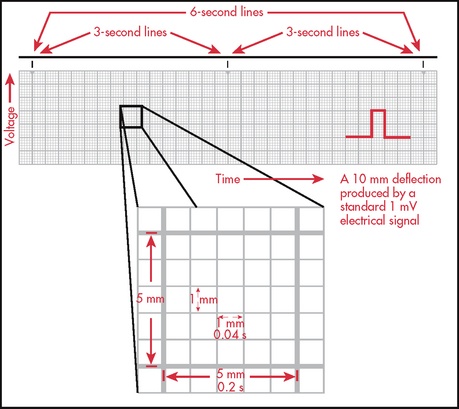
It is essential to know how to measure time and voltage on the ECG paper to correctly interpret an ECG. ECG paper consists of large (heavy lines) and small (light lines) squares (see Fig 35-6). Each large square incorporates 25 smaller squares (five horizontal and five vertical). Each small square represents 0.04 seconds horizontally and 0.1 mV vertically. This means that the large square equals 0.20 seconds and that 300 large squares equal 1 minute. Vertically, one large square is equal to 0.5 mV. These squares are used to calculate the heart rate (HR) and intervals between different ECG complexes.
A variety of methods can be used to calculate the HR from an ECG. Probably the most accurate way is to count the number of QRS complexes in 1 minute. However, this method is time consuming. If the rhythm is regular, a simpler process can be used. Every 3 seconds a marker appears on the ECG paper. The nurse can count the number of R-R intervals in 6 seconds and multiply that number by 10. An R wave is the first upward (or positive) deflection of the QRS complex. This will give the approximate number of beats per minute (see Fig 35-7).

Figure 35-7 When the rhythm is regular, the heart rate can be determined at a glance. The estimated heart rate is 70 beats/min.
Another rapid method for calculating the HR when the rhythm is regular is to count the number of small squares between one R-R interval. This number can be divided into 1500 to get the HR. The number of large squares between one R-R interval can also be counted and divided into 300 (see Fig 35-7). These methods are accurate only if the rhythm is regular.
An additional way to measure distances on the ECG strip is to use callipers. Callipers are used for fine measurements, especially for points of a specific wave or interval. Many times a P or R wave will not fall directly on a light or heavy line. The fine points of the callipers can be placed exactly on the components to be measured and then moved to another part of the strip for time measurement.
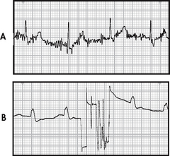
ECG leads are attached to the patient’s chest wall via an electrode pad fixed with electrical conductive paste. For best contact, excessive hair on the chest wall should be clipped using scissors. The skin should be prepared by rubbing gently with dry gauze until slightly pink. If the skin is oily, alcohol may be used first. In the case of a diaphoretic patient, benzoin may be applied to the skin before electrode placement. If leads and electrodes are not firmly placed, or if there is muscle activity or electrical interference from an outside source, an artefact may be seen on the monitor. An artefact is a distortion of the baseline and waveforms seen on the ECG (see Fig 35-8). Accurate interpretation of cardiac rhythm is difficult when an artefact is present. If artefacts occur, check for secure connections in the equipment. The electrodes on the patient may need to be removed and placed more securely or in areas that are less affected by movement.6
Telemetry monitoring
Telemetry monitoring is the observation of a patient’s HR and rhythm to diagnosis arrhythmias, ischaemia or infarction.7 Two types of systems are used for telemetry monitoring. The first type, a centralised monitoring system, requires the nurse to continuously observe all patients’ rhythms at a central location. The second system does not require constant nurse or technician surveillance. These systems have the capability of detecting and storing data. Sophisticated alarm systems provide different levels of detection of arrhythmias, ischaemia or infarction depending on the severity of each. However, computerised monitoring systems are not fail-proof. Frequent nursing assessment is important when caring for monitored patients.
ASSESSMENT OF CARDIAC RHYTHM
When assessing the cardiac rhythm, the nurse must make an accurate interpretation and immediately evaluate the consequences of the findings for the individual patient. Assessment of the patient’s haemodynamic response to any change in rhythm is essential, as this information will guide the selection of therapeutic interventions. Determination of the cause of arrhythmias should be a priority. For example, tachycardias may be the result of fever and possibly may cause a decrease in cardiac output (CO) and hypotension. Certain arrhythmias may be a result of electrolyte disturbances and may lead to a life-threatening arrhythmia.7 At all times, the patient, not the ‘monitor’, must be assessed and treated.
Normal sinus rhythm refers to a rhythm that originates in the SA node and follows the normal conduction pattern of the cardiac cycle (see Fig 35-9). Figure 35-10 shows the normal electrical pattern of the cardiac cycle. Table 35-2 provides a description of ECG waveforms and intervals and possible sources of disturbances in these features. The P wave represents the depolarisation of the atria (passage of an electrical impulse through the atria), causing atrial contraction. The PR interval represents the time period for the impulse to spread through the atria, AV node, bundle of His and Purkinje fibres. The QRS complex represents depolarisation of the ventricles (ventricular contraction) and the QRS interval represents the time it takes for depolarisation. The ST segment represents the time between ventricular depolarisation and repolarisation. This segment should be flat or isoelectric and represents the absence of any electrical activity between these two events. The T wave represents repolarisation of the ventricles. The QT interval represents the total time for depolarisation and repolarisation of the ventricles.
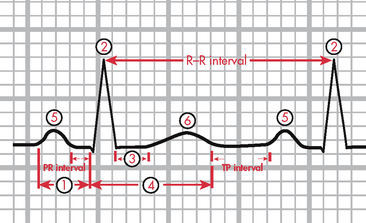
Figure 35-10 The electrocardiogram complex as seen in normal sinus rhythm. 1, P wave (normal is 0.06–0.12 s); 2, PR interval (normal is 0.12–0.20 s); 3, QRS complex (normal is 0.04–0.12 s); 4, ST segment (normal is 0.12 s); 5, T wave (normal is 0.16 s); 6, QT interval (normal is 0.34–0.43 s). Isoelectric (flat) line represents the absence of electrical activity in the cardiac cells.
TABLE 35-2 Definition and sources of disturbance in electrocardiogram waveforms and intervals*
| Description | Duration (s) | Source of disturbance |
|---|---|---|
| P wave: Represents time taken for the passage of the electrical impulse through the atria causing atrial depolarisation; should be upright | 0.06-0.12 | Disturbance in conduction within atria |
| PR interval: Measured from beginning of P wave to beginning of QRS complex; represents time taken for impulse to spread through the atria, AV node and bundle of his, the bundle branches and Purkinje fibres, to a point immediately preceding ventricular contraction | 0.12-0.20 | Disturbance in conduction usually in AV node, bundle of his or bundle branches, but can be in atria as well |
| QRS interval: Measured from beginning to end of QRS complex; represents time taken for depolarisation of both ventricles | 0.04-0.12 | Disturbance in conduction in bundle branches or in ventricles |
| ST segment: Measured from the S wave of the QRS to the beginning of the T wave; represents the time between ventricular depolarisation and repolarisation; should be flat (isoelectric) | 0.12 | Disturbances usually caused by ischaemia or infarction |
| T wave: Represents time taken for ventricular repolarisation; should be upright | 0.16 | Disturbances usually caused by electrolyte imbalances, ischaemia or infarction |
| QT interval: Measured from beginning of QRS to end of T wave; represents time taken for entire electrical depolarisation and repolarisation of the ventricles | 0.34-0.43 | Disturbances usually affecting repolarisation more than depolarisation and caused by drugs, electrolyte imbalances and changes in heart rate |
*Heart rate influences the duration of these intervals, especially those of the PR and QT intervals. AV, atrioventricular.
ELECTROPHYSIOLOGICAL MECHANISMS OF ARRHYTHMIAS
Disorders of impulse formation can cause arrhythmias. The heart has specialised cells found in the SA node, parts of the atria, the AV node and the bundle of His and Purkinje (His–Purkinje) system, which are able to discharge spontaneously. This is termed automaticity. Normally the main pacemaker of the heart is the SA node, which spontaneously discharges 60–100 times per minute (see Table 35-3). A pacemaker from another site may be discharged in two ways. If the SA node discharges more slowly than a secondary pacemaker, the electrical discharges from the secondary pacemaker may passively ‘escape’. The secondary pacemaker will then discharge automatically at its intrinsic rate. These secondary pacemakers may originate from the AV node or His–Purkinje system at rates of 40–60 times per minute and 20–40 times per minute, respectively. The other way that secondary pacemakers can originate is when they discharge more rapidly than the normal pacemaker of the SA node. Triggered beats (early or late) may come from an ectopic focus (area outside the normal conduction pathway) in the atria, AV node or ventricles. This may result in an arrhythmia, which replaces the normal sinus rhythm.
TABLE 35-3 Intrinsic rates of the conduction system
| Site of conduction | Rate |
|---|---|
| Sinoatrial node | 60-100 times/min |
| Atrioventricular node | 40-60 times/min |
| Bundle of his, Purkinje fibres | 20-40 times/min |
The impulse started by the SA node or an ectopic focus must be conducted to the entire heart chamber. The property of myocardial tissue that allows it to be depolarised by a stimulus is called excitability. This is an important part of the transmission of the impulse from one fibre to another. The level of excitability is determined by the length of time after depolarisation that the tissues can be restimulated. The recovery period after stimulation is called the refractory period or phase. The absolute refractory period occurs when excitability is zero and heart tissue cannot be stimulated. The relative refractory period occurs slightly later in the cycle and excitability is more likely. In states of full excitability, the heart is completely recovered. Figure 35-11 shows the relationship between the refractory period and the ECG.
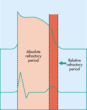
Figure 35-11 Absolute and relative refractory periods correlated with the cardiac muscle’s action potential and with an electrocardiograph tracing.
If conduction is depressed and if some areas of the heart are blocked (e.g. by necrosis), the unblocked areas are activated earlier than the blocked areas. When the block is unidirectional, this uneven conduction may allow the initial impulse to re-enter areas that were previously not excitable but have recovered. The re-entering impulse may be able to depolarise the atria and ventricles, causing a premature beat. If the re-entrant excitation continues, tachycardia occurs.3
EVALUATION OF ARRHYTHMIAS
Arrhythmias occur as the result of various abnormalities and disease states.3,7 The cause of an arrhythmia influences the treatment of the patient. Common causes of arrhythmias are presented in Box 35-1. Box 35-2 presents a systematic approach to assessing a cardiac rhythm.
BOX 35-2 Systematic approach to assessing cardiac rhythm
When assessing a cardiac rhythm, a systematic approach should be used. A recommended approach includes the following:
1. Note the P wave. Is it upright or inverted? Is there one for every QRS?
2. Evaluate the atrial rhythm. Is it regular or irregular?
4. Measure the duration of the PR interval. Is it of normal duration or prolonged?
5. Evaluate the ventricular rhythm. Is it regular or irregular?
6. Calculate the ventricular rate.
7. Measure the duration of the QRS complex. Is it of normal duration or prolonged?
8. Assess the ST segment. Is it isoelectric, elevated or depressed?
9. Measure the duration of the QT interval. Is it of normal duration or prolonged?
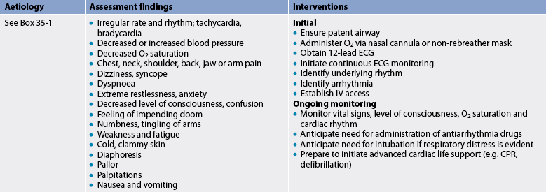
Arrhythmias occurring in out-of-hospital settings present problems of management. Determination of the rhythm by cardiac monitoring is a high priority. If indicated, the emergency medical services (EMS) system is activated after the patient has been assessed. Emergency care of the patient with an arrhythmia is outlined in Table 35-4.
In addition to continuous ECG monitoring during hospitalisation, several other methods are used to evaluate cardiac arrhythmias and the effectiveness of antiarrhythmia drug therapy. An electrophysiology study (an invasive method) and Holter monitoring, event recorder monitoring, exercise treadmill testing and signal-averaged ECG (all non-invasive methods) can be performed on both an inpatient and an outpatient basis.
An electrophysiology study (EPS) is performed to identify different mechanisms of tachyarrhythmias (arrhythmias with rates >100 beats/min), as well as heart blocks, bradyarrhythmias (arrhythmias with rates <100 beats/min) and causes of syncope. It can also be used to identify locations of accessory pathways and to determine the effectiveness of antiarrhythmic drugs. It involves introducing several electrode catheters transvenously through the femoral vein to the right side of the heart with fluoroscopic guidance. Electrical stimulation to various areas of the atrium and ventricle is performed to induce the arrhythmia. Immediate cardioversion or defibrillation may be required as serious arrhythmias can be provoked during the procedure.
Preprocedure anxiety is common for the patient undergoing EPS. Emotional support from the nurse is important. Patients should be instructed that they will be sedated but conscious during the procedure. Nursing care before and after the procedure is similar to that for cardiac catheterisation (see Ch 31). (EPS testing is also discussed in Ch 31.)
The Holter monitor is a device that records the ECG while the patient is ambulatory. The device can record heart rhythm for 24–48 hours while the patient performs daily activities. The patient maintains a diary in which activities and any symptoms are recorded. Events in the diary can later be correlated with any arrhythmias observed on the recording. The monitor is generally a useful device for detecting significant arrhythmias and evaluating the effects of drugs during a patient’s normal activities. It can also be used for detecting ischaemia by analysing ST segments. A limitation of the device is that the patient who has frequent ventricular arrhythmias, some of which may be lethal, may not have these arrhythmias during the monitored time. (Holter monitoring is also discussed in Ch 31.)
Use of event monitors has greatly improved the evaluation of arrhythmias in the outpatient. Event monitors are activated by the patient and can be used only at the time the patient experiences symptoms. The recorder is placed over the patient’s chest during symptoms. The patient then transmits the rhythm to a central monitoring company via telephone. This is an easier method of documenting an arrhythmia than the 24-hour monitor, especially if symptoms are not occurring daily. (Ambulatory ECG monitoring is discussed in Ch 31.)
The signal-averaged ECG (SAECG) is a high-resolution ECG used to identify patients at risk of developing complex ventricular arrhythmias. A computerised program and ECG machine are used for the test. The identification of electrical activity called late potentials on the SAECG strongly suggests that a patient is at risk of developing serious ventricular arrhythmias.
Exercise treadmill testing is used for evaluation of cardiac rhythm response to exercise. Exercise-induced arrhythmias can be reproduced and analysed and drug therapy can be evaluated. These tests are performed with routine treadmill testing protocols.
Diagnostic procedures for assessment of the cardiovascular system are presented in Table 31-7.
TYPES OF ARRHYTHMIAS
Examples of the ECG tracings of common arrhythmias are presented in Figures 35-12 to 35-20. Descriptive characteristics of common arrhythmias are presented in Table 35-5.

Figure 35-14 Paroxysmal supraventricular tachycardia (PSVT). Arrows indicate beginning and ending of PSVT.
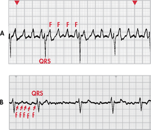
Figure 35-15 A, Atrial flutter with a 4:1 conduction (four flutter [F] waves to each QRS complex). B, Atrial fibrillation. Note the chaotic fibrillatory (f) waves between the QRS complexes. Note: Recorded from lead V1.
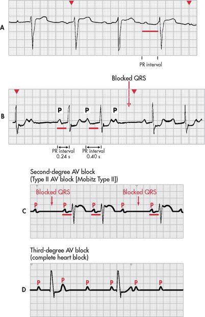
Figure 35-17 Heart block. A, First-degree atrioventricular (AV) heart block with a PR interval of 0.36 seconds. B, Second-degree AV heart block, type I, with progressive lengthening of the PR interval until a QRS is blocked. C, Second-degree AV heart block, type II, with constant PR intervals and variable blocked QRS complexes. D, Third-degree AV block. Note there is no relationship between P waves and QRS complexes.
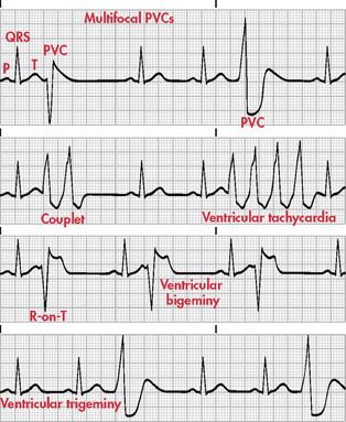
Figure 35-18 Various forms of premature ventricular contractions (PVCs). Note: Recorded from lead II.
TABLE 35-5 Characteristics of common arrhythmias
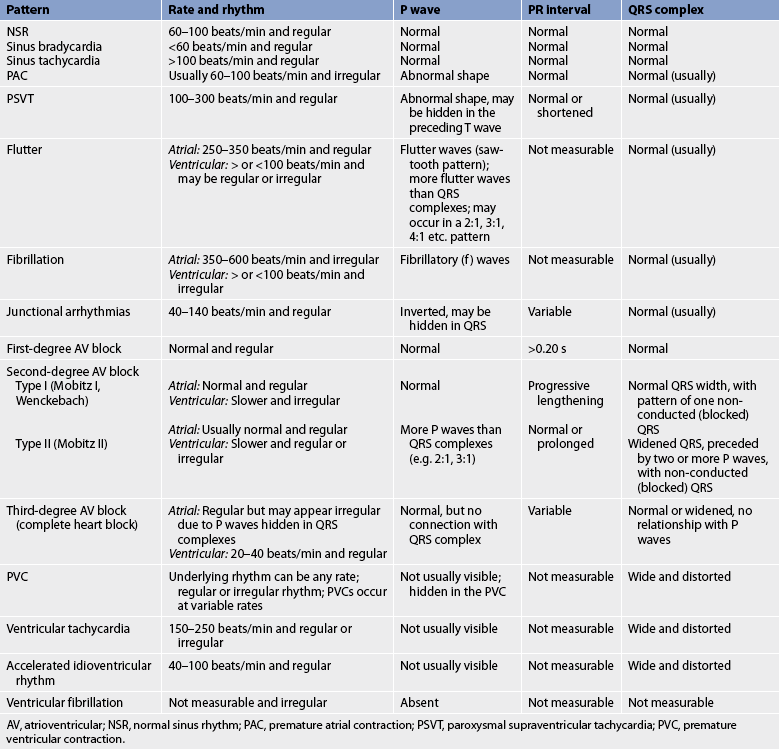
AV, atrioventricular; NSR, normal sinus rhythm; PAC, premature atrial contraction; PSVT, paroxysmal supraventricular tachycardia; PVC, premature ventricular contraction.
Sinus bradycardia
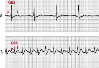
In sinus bradycardia the conduction pathway is the same as that in normal sinus rhythm but the SA node fires at a rate less than 60 beats/min. This is referred to as absolute bradycardia (see Fig 35-12, A). Relative bradycardia refers to a HR that is less than expected for the patient’s condition, causing the patient to be symptomatic.7
Clinical associations
Sinus bradycardia may be a normal sinus rhythm in aerobically trained athletes and in other individuals during sleep. It also occurs in response to carotid sinus massage, Valsalva manoeuvre, hypothermia, increased intraocular pressure, increased vagal tone and administration of parasympathomimetic drugs (e.g. bethanechol). Disease states associated with sinus bradycardia are hypothyroidism, increased intracranial pressure, obstructive jaundice and inferior wall myocardial infarction (MI).
ECG characteristics
In sinus bradycardia, the HR is less than 60 beats/min and the rhythm is regular. The P wave precedes each QRS complex and has a normal shape and duration. The PR interval is normal and the QRS complex has a normal shape and duration.
Sinus tachycardia
The conduction pathway is the same in sinus tachycardia as that in normal sinus rhythm. The discharge rate from the sinus node is increased as a result of vagal inhibition or sympathetic stimulation. The sinus rate is greater than 100 beats/min (see Fig 35-12, B).
Clinical associations
Sinus tachycardia is associated with physiological and psychological stressors such as exercise, fever, pain, hypotension, hypovolaemia, anaemia, hypoxia, hypoglycaemia, myocardial ischaemia, heart failure (HF), hyperthyroidism, anxiety and fear. It can also be an effect of drugs such as adrenaline, noradrenaline, atropine, caffeine, theophylline, nifedipine or hydralazine. In addition, many over-the-counter cold remedies have active ingredients (e.g. pseudoephedrine) that can cause tachycardia.
ECG characteristics
In sinus tachycardia, the HR is greater than 100 beats/min and the rhythm is regular. The P wave is normal, precedes each QRS complex and has a normal shape and duration. The PR interval is normal and the QRS complex has a normal shape and duration.
Clinical significance
The clinical significance of sinus tachycardia depends on the patient’s tolerance of the increased HR. The patient may have symptoms of dizziness, dyspnoea and hypotension. Increased myocardial oxygen consumption is associated with an increased HR. Angina or an increase in infarction size may accompany persistent sinus tachycardia in the patient with an acute MI.
Treatment
Treatment is often based on the underlying cause. If the patient is experiencing tachycardia from pain, tachycardia should resolve with effective pain management. Treating hypovolaemia should resolve any associated tachycardia. In certain situations, intravenous (IV) adenosine and β-adrenergic blockers (e.g. metoprolol) may be used to reduce the HR and decrease myocardial oxygen consumption.
Premature atrial contraction
A premature atrial contraction (PAC) is a contraction originating from an ectopic focus in the atrium in a location other than the sinus node. The ectopic signal originates in the left or right atrium and travels across the atria by an abnormal pathway, creating a distorted P wave (see Fig 35-13). At the AV node, it may be stopped (non-conducted PAC), delayed (lengthened PR interval) or conducted normally. If the signal moves through the AV node, in most cases it is conducted normally through the ventricles.
Clinical associations
In a normal heart, a PAC can result from emotional stress or physical fatigue, or from the use of caffeine, tobacco or alcohol. It can also result from hypoxia, electrolyte imbalances and disease states such as hyperthyroidism, chronic obstructive pulmonary disease (COPD) and heart disease, including coronary artery disease (CAD) and valvular disease.
ECG characteristics
The HR varies with the underlying rate and frequency of the PAC and the rhythm is irregular. The P wave has a different shape from that of the P wave originating from the SA node. It may be notched or have downward (or negative) deflection, or it may be hidden in the preceding T wave. The PR interval may be shorter or longer than the PR interval originating from the SA node, but it is within normal limits. The QRS complex is usually normal. If the QRS interval is 0.12 seconds or longer, abnormal conduction through the ventricles is present.
Clinical significance
In patients with healthy hearts, isolated PACs are not significant. In patients with heart disease, frequent PACs may indicate enhanced automaticity of the atria or a re-entry mechanism. Such PACs may warn of, or initiate, more serious arrhythmias (e.g. supraventricular tachycardia).
Paroxysmal supraventricular tachycardia
Paroxysmal supraventricular tachycardia (PSVT) is an arrhythmia originating in an ectopic focus anywhere above the bifurcation of the bundle of His (see Fig 35-14). Identification of the ectopic focus is often difficult, even with a 12-lead ECG, as it requires recording the arrhythmia as it is initiated.
PSVT occurs because of a re-entrant phenomenon (re-excitation of the atria when there is a one-way block). Usually a PAC triggers a run of repeated premature beats. Paroxysmal refers to an abrupt onset and termination. Termination is sometimes followed by a brief period of asystole. Some degree of AV block may be present. PSVT can occur in the presence of Wolff-Parkinson-White (WPW) syndrome, or ‘pre-excitation’. In this syndrome, there are extra conduction pathways, or accessory pathways.
Clinical associations
In the normal heart, PSVT is associated with overexertion, emotional stress, deep inspiration and stimulants such as caffeine and tobacco. It is also associated with rheumatic heart disease, digoxin toxicity, CAD and cor pulmonale.
ECG characteristics
In PSVT, the HR is 100–300 beats/min and the rhythm is regular or slightly irregular. The P wave is often hidden in the preceding T wave but if seen it may have an abnormal shape. The PR interval may be shortened or normal and the QRS complex is usually normal.
Clinical significance
The clinical significance of PSVT depends on symptoms and the HR. A prolonged episode and HR greater than 180 beats/min may precipitate a decreased CO, resulting in hypotension, dyspnoea and angina.
Treatment
Treatment for PSVT includes vagal stimulation and drug therapy. Common vagal manoeuvres include Valsalva and coughing. IV adenosine is the first drug of choice to convert PSVT to a normal sinus rhythm. This drug has a short half-life (10 seconds) and is well tolerated by most patients.3,7 IV β-adrenergic blockers and calcium channel blockers (e.g. diltiazem, digoxin and amiodarone) can also be used. For a patient with WPW, amiodarone should be used. If vagal stimulation and drug therapy are ineffective and the patient becomes haemodynamically unstable, direct current (DC) cardioversion may be used.7
If PSVT recurs in patients with WPW, they may ultimately be treated with radiofrequency catheter ablation of the accessory pathway.8 (Catheter ablation therapy is discussed on p 934.)
Atrial flutter
Atrial flutter is an atrial tachyarrhythmia identified by recurring, regular, sawtooth-shaped flutter (F) waves that originate from a single ectopic focus in the right atrium (see Fig 35-15, A).3
Clinical associations
Atrial flutter rarely occurs in a normal heart. In disease states, it is associated with CAD, hypertension, mitral valve disorders, pulmonary embolus, chronic lung disease, cor pulmonale, cardiomyopathy, hyperthyroidism and the use of drugs such as digoxin, quinidine and adrenaline.
ECG characteristics
The atrial rate is 250–350 beats/min. The ventricular rate varies according to the conduction ratio. In 2:1 conduction, the ventricular rate is typically found to be approximately 150 beats/min. Atrial rhythm is regular and ventricular rhythm is usually regular. The atrial flutter waves represent atrial depolarisation followed by repolarisation. The PR interval is variable and not able to be measured. The QRS complex is usually normal. Because of the ability of the AV node to delay signals from the atria, there is usually some AV block in a fixed ratio of flutter waves to QRS complexes (e.g. 2:1, 3:1).
Clinical significance
High ventricular rates (>100 beats/min) and loss of the atrial ‘kick’ (atrial contraction reflected by a sinus P wave) that is associated with atrial flutter can decrease CO and cause serious consequences, such as HF, especially in patients with underlying heart disease.8 Patients with atrial flutter are at increased risk of stroke because of the risk of thrombus formation in the atria from the stasis of blood. Warfarin is used to prevent stroke in patients with atrial flutter of greater than 48 hours duration.7,8
Treatment
The primary goal in the treatment of atrial flutter is to slow the ventricular response by increasing AV block. Drugs used to control the ventricular rate include calcium channel blockers and β-adrenergic blockers. Electrical cardioversion may be used to convert the atrial flutter to normal sinus rhythm in an emergency situation (i.e. the patient is haemodynamically unstable) and electively. Antiarrhythmia drugs used to convert atrial flutter to normal sinus rhythm or maintain normal sinus rhythm include amiodarone, propafenone, procainamide and flecainide.7
Radiofrequency catheter ablation is increasingly being used as curative therapy for atrial flutter. The procedure is done in the electrophysiology laboratory and involves positioning a catheter in the right atrium between the tricuspid valve and the inferior vena cava. Using a low-voltage high-frequency form of electrical energy, the tissue is ablated (or destroyed), the arrhythmia is terminated and normal sinus rhythm is restored in most cases.9
Atrial fibrillation
Atrial fibrillation is characterised by a total disorganisation of atrial electrical activity due to multiple ectopic foci resulting in loss of effective atrial contraction (see Fig 35-15, B). The arrhythmia may be chronic or intermittent. Atrial fibrillation is the most common arrhythmia in Australia and New Zealand, occurring in 2% of the general population.10 Its prevalence increases with age, so that 1 in 10 adults aged over 75 years are currently affected; therefore, the proportion of the population affected will increase substantially in the next few decades.
Clinical associations
Atrial fibrillation usually occurs in patients with underlying heart disease, such as CAD, rheumatic heart disease, cardiomyopathy, hypertensive heart disease, HF and pericarditis. It is often acutely caused by factors such as thyrotoxicosis, alcohol intoxication, caffeine use, electrolyte disturbances, stress and cardiac surgery.
ECG characteristics
During atrial fibrillation, the atrial rate may be as high as 350–600 beats/min, while the ventricular rate can vary from as low as 50 beats/min to as high as 180 beats/min. Atrial fibrillation with a ventricular rate greater than 100 beats/min is described as atrial fibrillation with a rapid ventricular response. When the ventricular rate is less than 100 beats/min, it is described as atrial fibrillation with a slow or controlled ventricular response. P waves are replaced by chaotic, fibrillatory waves in atrial fibrillation. The ventricular rhythm is usually irregular. The PR interval is not measurable and the QRS complex usually has a normal shape and duration. At times, atrial flutter and atrial fibrillation may coexist.
Clinical significance
Atrial fibrillation can often result in a decrease in CO because of ineffective atrial contractions, loss of atrial kick and/or a rapid ventricular response. Thrombi may form in the atria as a result of blood stasis. An embolised clot may pass to the brain, causing a stroke. Overall risk of stroke increases fivefold with atrial fibrillation. Risk of stroke is even higher in patients with structural heart disease, with hypertension and who are over 65 years of age.8
Treatment
The goals of treatment include a decrease in the ventricular response (to <100 beats/min) and the prevention of cerebral embolic events.11–14 Ventricular rate control is a priority for patients with atrial fibrillation. Drugs used for rate control include calcium channel blockers (e.g. diltiazem), β-adrenergic blockers (e.g. metoprolol) and digoxin.
For some patients, conversion of atrial fibrillation to a normal sinus rhythm may be a consideration (e.g. reduced exercise tolerance with rate control drugs, contraindications to warfarin).11,12 Antiarrhythmia drugs used for conversion to and maintenance of normal sinus rhythm include amiodarone, propafenone, flecainide and procainamide.7 In patients with severe left ventricular dysfunction (ejection fraction <40%) or HF, amiodarone or DC cardioversion should be used.7
Cardioversion may be used to convert atrial fibrillation to normal sinus rhythm. If a patient has been in atrial fibrillation for more than 48 hours, anticoagulation therapy with warfarin is recommended for 3–4 weeks before any attempt at cardioversion and for 4–6 weeks after successful cardioversion.7 Prior to the procedure, a transoesophageal echocardiogram may be performed to rule out the presence of thrombi (clots) in the atria. The cardioversion procedure can cause the clots to dislodge, placing the patient at risk of stroke. If clots are present, the procedure is contraindicated.
If drugs or cardioversion do not convert atrial fibrillation to normal sinus rhythm, long-term anticoagulation therapy is required.11–14 Warfarin is the drug of choice and patients are monitored for therapeutic levels (e.g. INR in the 2–3 range). (See Ch 37 for discussion of anticoagulation therapy.)
Other treatment strategies exist for patients with drug-refractory atrial fibrillation or who cannot or choose not to have long-term anticoagulation. These include the use of radiofrequency catheter ablation (similar to the procedure for atrial flutter) and the Maze procedure.15,16 The Maze procedure is a surgical intervention that stops atrial fibrillation by interrupting the ectopic electrical signals that are responsible for this arrhythmia. Incisions are made in both atria to stop the formation and conduction of these signals. Scar tissue generated by the incisions permanently blocks the paths of the ectopic signals that cause atrial fibrillation and restores normal sinus rhythm. Modifications to the Maze procedure include the use of cold (cryoablation) and heat (high intensity ultrasound) rather than incisions to destroy the areas of the atria associated with the arrhythmia.16
Junctional arrhythmias
Junctional arrhythmias refer to arrhythmias that originate in the area of the AV node, primarily because the SA node has failed to fire or the signal has been blocked. In this situation, the AV node becomes the pacemaker of the heart. The impulse from the AV node usually moves in a retrograde (backward) fashion that produces an abnormal P wave occurring just before or after the QRS complex or that is hidden in the QRS complex. The impulse usually moves normally through the ventricles. Junctional premature beats may occur and they are treated in a manner similar to that for PACs. Other junctional arrhythmias include junctional escape rhythm (see Fig 35-16), accelerated junctional rhythm and junctional tachycardia. These arrhythmias are treated according to the patient’s tolerance of the rhythm and clinical condition.
Clinical associations
Junctional arrhythmias are often associated with CAD, HF, cardiomyopathy, electrolyte imbalances, inferior MI and rheumatic heart disease. Certain drugs (e.g. digoxin, amphetamines, caffeine, nicotine) can also cause junctional arrhythmias.3
ECG characteristics
In junctional escape rhythm the HR is 40–60 beats/min, in accelerated junctional rhythm it is 61–100 beats/min and in junctional tachycardia it is 101–150 beats/min. Rhythm is regular. The P wave is abnormal in shape and inverted, or it may be hidden in the QRS complex (see Fig 35-16). The PR interval is less than 0.12 seconds when the P wave precedes the QRS complex. The QRS complex is usually normal.
Clinical significance
Junctional escape rhythms serve as a safety mechanism occurring when the SA node has not been effective. Escape rhythms such as this should not be suppressed. Accelerated junctional rhythm and junctional tachycardia indicate a more serious problem with the SA node. These rhythms may result in a reduction of CO, causing the patient to become haemodynamically unstable (e.g. hypotensive).3
Treatment
Treatment varies according to the type of junctional arrhythmia. If a patient has symptoms with an escape junctional rhythm, atropine can be used. In accelerated junctional rhythm and junctional tachycardia caused by digoxin toxicity, the digoxin is withheld. In the absence of digoxin toxicity, β-adrenergic blockers, calcium channel blockers and amiodarone are used for rate control. DC cardioversion should not be used.7
First-degree AV block
First-degree AV block is a type of AV block in which every impulse is conducted to the ventricles but the duration of AV conduction is prolonged (see Fig 35-17, A). After the impulse moves through the AV node, it is usually conducted normally through the ventricles.
Clinical associations
First-degree AV block is associated with MI, CAD, rheumatic fever, hyperthyroidism, vagal stimulation and drugs such as digoxin, β-adrenergic blockers, calcium channel blockers and flecainide.
ECG characteristics
In first-degree AV block, the HR is normal and rhythm is regular. The P wave is normal, the PR interval is prolonged for more than 0.20 seconds and the QRS complex usually has a normal shape and duration.
Type I second-degree AV block
Type I second-degree AV block (Mobitz I or Wenckebach) includes a gradual lengthening of the PR interval. It occurs because of a prolonged AV conduction time until an atrial impulse is non-conducted and a QRS complex is blocked (missing) (see Fig 35-17, B). Type I AV block most commonly occurs in the AV node, but it can also occur in the His–Purkinje system.
Clinical associations
Type I AV block may result from use of drugs such as digoxin or β-adrenergic blockers. It may also be associated with CAD and other diseases that can slow AV conduction.
ECG characteristics
The atrial rate is normal, but the ventricular rate may be slower as a result of non-conducted or blocked QRS complexes. Once a ventricular beat is blocked, the cycle repeats itself with progressive lengthening of the PR intervals until another QRS complex is blocked. The rhythm appears on the ECG in a pattern of grouped beats. Ventricular rhythm is irregular. The P wave has a normal shape, and the QRS complex has a normal shape and duration.
Clinical significance
Type I AV block is usually a result of myocardial ischaemia or infarction. It is almost always transient and is usually well tolerated. However, in some patients (e.g. following MI) it may be a warning signal of a more serious AV conduction disturbance.
Treatment
If the patient is symptomatic, atropine is used to increase the HR or a temporary pacemaker may be needed, especially if the patient has experienced an MI. If the patient is asymptomatic, the rhythm should be closely observed with a transcutaneous pacemaker on standby. Bradycardia is more likely to become symptomatic when one or more of the following are present: (1) hypotension; (2) HF; or (3) shock.
Type II second-degree AV block
In type II second-degree AV block (Mobitz II) a P wave is non-conducted without progressive antecedent PR lengthening. This almost always occurs when a block in one of the bundle branches is present (see Fig 35-17, C). On conducted beats, the PR interval is constant. Type II AV heart block is a more serious type of block in which a certain number of impulses from the SA node are not conducted to the ventricles. This occurs in ratios of 2:1, 3:1 and so on (i.e. two P waves to one QRS complex, three P waves to one QRS complex and so on). It may occur with varying ratios. Type II AV block almost always occurs in the His–Purkinje system.
Clinical associations
Type II AV block is associated with rheumatic heart disease, CAD, anterior MI and digoxin toxicity.
ECG characteristics
The atrial rate is usually normal. The ventricular rate depends on the intrinsic rate and the degree of AV block. Atrial rhythm is regular, but ventricular rhythm may be irregular. The P wave has a normal shape. The PR interval may be normal or prolonged in duration and remains constant on conducted beats. The QRS complex is usually more than 0.12 seconds because of bundle branch block.
Third-degree AV block
Third-degree AV block, or complete heart block, constitutes one form of AV dissociation in which no impulses from the atria are conducted to the ventricles (see Fig 35-17, D). The atria are stimulated and contract independently of the ventricles. The ventricular rhythm is an escape rhythm and the ectopic pacemaker may be above or below the bifurcation of the bundle of His.
Clinical associations
Third-degree AV block is associated with severe heart disease including CAD, MI, myocarditis, cardiomyopathy and some systemic diseases such as amyloidosis and progressive systemic sclerosis (scleroderma). Some medications can also cause third-degree AV block, such as digoxin, β-adrenergic blockers and calcium channel blockers.
ECG characteristics
The atrial rate is usually a sinus rate of 60–100 beats/min. The ventricular rate depends on the site of the block. If it is in the AV node, the rate is 40–60 beats/min and if it is in the Purkinje system, it is 20–40 beats/min. Atrial and ventricular rhythms are regular but unrelated to each other. The P wave has a normal shape. The PR interval is variable and there is no time relationship between the P wave and the QRS complex. The QRS complex is normal if an escape rhythm is initiated at the bundle of His or above, and it is widened if an escape rhythm is initiated below the bundle of His.
Clinical significance
Third-degree AV block almost always results in reduced CO with subsequent ischaemia, HF and shock. Syncope from third- degree AV block may result from severe bradycardia or even periods of asystole.
Treatment
For symptomatic patients, a transcutaneous pacemaker is used until a temporary transvenous pacemaker can be inserted.7 The use of drugs such as atropine, adrenaline, isoprenaline and dopamine is a temporary measure to increase the HR and support blood pressure (BP) until temporary pacing is initiated. Patients will need a permanent pacemaker as soon as possible.
Premature ventricular contractions
A premature ventricular contraction (PVC) is a contraction originating in an ectopic focus in the ventricles. It is the premature occurrence of a QRS complex, which is wide and distorted in shape, compared with a QRS complex initiated from the normal conduction pathway (see Fig 35-18). PVCs that are initiated from different foci appear different in shape from each other and are called multifocal PVCs. PVCs that appear to have the same shape are called unifocal PVCs. When every other beat is a PVC, it is called ventricular bigeminy. When every third beat is a PVC, it is called ventricular trigeminy. Two consecutive PVCs are called a couplet.
Ventricular tachycardia occurs when there are three or more consecutive PVCs. R on T phenomenon occurs when a PVC falls on the T wave of a preceding beat. This is considered especially dangerous as the PVC is firing during the relative refractory phase of ventricular repolarisation. Excitability of the cardiac cells is increased during this time and the risk of the PVC initiating ventricular tachycardia or ventricular fibrillation is great.
Clinical associations
PVCs are associated with stimulants such as caffeine, alcohol, nicotine, aminophylline, adrenaline, isoproterenol and digoxin. They are also associated with electrolyte imbalances, hypoxia, fever, exercise and emotional stress. Disease states associated with PVCs include MI, mitral valve prolapse, HF and CAD.
ECG characteristics
The HR varies according to the intrinsic rate and number of PVCs. Rhythm is irregular because of premature beats. The P wave is rarely visible and is usually lost in the QRS complex. Retrograde conduction may occur and the P wave may be seen following the ectopic beat. The PR interval is not measurable. The QRS complex is wide and distorted in shape, more than 0.12 seconds. The T wave is generally large and opposite in direction to the major direction of the QRS complex.
Clinical significance
PVCs are usually a benign finding in the patient with a normal heart. In heart disease, depending on frequency, PVCs may reduce the CO and precipitate angina and HF. Because PVCs in CAD or acute MI represent ventricular irritability, the patient’s physiological response to PVCs must be monitored. It is important to assess the patient’s apical–radial pulse rate as some PVCs may not generate a sufficient ventricular contraction to result in a peripheral pulse. This may lead to a pulse deficit.
Treatment
Treatment is often based on the cause of the PVCs (e.g. oxygen therapy, electrolyte replacement). Assessment of the patient’s haemodynamic status is important to determine whether treatment with drug therapy is indicated. Drugs that should be considered include β-adrenergic blockers, procainamide, amiodarone and lignocaine.
Ventricular tachycardia
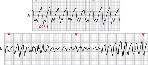
The diagnosis of ventricular tachycardia (VT) is made when a run of three or more PVCs occurs. It occurs when an ectopic focus (or foci) fires repetitively and the ventricle takes control as the pacemaker. Different forms of VT exist, depending on QRS configuration. Monomorphic VT (see Fig 35-19, A) has QRS complexes that are the same in shape, size and direction. Polymorphic VT occurs when the QRS complexes gradually change back and forth from one shape, size and direction to another over a series of beats. Torsades de pointes (French, ‘twisting around a point’) is polymorphic VT associated with a prolonged QT interval of the underlying rhythm (see Fig 35-19, B).
VT may be sustained or non-sustained. Sustained VT lasts for greater than 30 seconds, while non-sustained VT lasts for 30 seconds or less. The appearance of ventricular tachycardia is an ominous sign. It is considered to be a life-threatening arrhythmia because of decreased CO and the possibility of deterioration to ventricular fibrillation, which is a lethal arrhythmia.
Clinical associations
Ventricular tachycardia is associated with MI, CAD, significant electrolyte imbalances, cardiomyopathy, mitral valve prolapse, long QT syndrome, digoxin toxicity and central nervous system disorders. The arrhythmia has also been observed in patients who have no evidence of cardiac disease.
ECG characteristics
The ventricular rate is 150–250 beats/min. Rhythm may be regular or irregular. AV dissociation may be present, with P waves occurring independently of the QRS complex. The atria may also be depolarised by the ventricles in a retrograde fashion. The P wave is usually buried (hidden) in the QRS complex and the PR interval is not measurable. The QRS complex is distorted in appearance, with a duration exceeding 0.12 seconds and with the ST–T wave in the opposite direction of the QRS complex (see Fig 35-19). The R-R interval may be irregular or regular.
Clinical significance
VT can be stable (patient has a pulse) or unstable (patient is pulseless). Sustained ventricular tachycardia will cause a severe decrease in CO as a result of decreased ventricular diastolic filling times and loss of atrial contraction. Results include hypotension, pulmonary oedema, decreased cerebral blood flow and cardiopulmonary arrest. The arrhythmia must be treated quickly, even if it occurs only briefly and stops abruptly. Episodes may recur if prophylactic treatment is not begun. Ventricular fibrillation may also develop.
Treatment
Precipitating causes must be identified and treated (e.g. electrolyte imbalances, ischaemia). If the VT is monomorphic and the patient is haemodynamically stable (e.g. pulse is present) and has preserved left ventricular function, IV procainamide, sotalol, amiodarone or lignocaine is used. If the patient becomes haemodynamically unstable or has poor left ventricular function, IV amiodarone or lignocaine is given followed by cardioversion.
If VT is polymorphic with a normal baseline QT interval, any one of the following medications is used: β-adrenergic blockers, lignocaine, amiodarone, procainamide or sotalol. Cardioversion is used if drug therapy is ineffective.
If VT is polymorphic with a prolonged baseline QT interval, therapies include IV magnesium, isoproterenol, phenytoin, lignocaine or anti-tachycardia pacing. Drugs that prolong the QT interval should be discontinued. If the rhythm is not converted, cardioversion may be needed.
VT without a pulse is a life-threatening situation and is treated in the same manner as ventricular fibrillation. Rapid defibrillation is the first line of treatment, followed by the administration of adrenaline if defibrillation is unsuccessful.7
An accelerated idioventricular rhythm (AIVR) can develop when the intrinsic pacemaker rate (SA node or AV node) becomes less than that of a ventricular ectopic pacemaker. The rate is between 40 and 100 beats/min. It is most commonly associated with acute MI and reperfusion of myocardium after fibrinolytic therapy or angioplasty of the coronary arteries. It can be seen with digoxin toxicity. In the setting of acute MI, AIVR is usually self-limiting, well tolerated and requires no treatment. If the patient becomes symptomatic (e.g. hypotension, angina), atropine can be considered. Temporary pacing may be required. Drugs that suppress ventricular rhythms (e.g. lignocaine) should not be used as these can terminate the ventricular rhythm and further reduce the heart rate.
Ventricular fibrillation
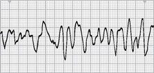
Ventricular fibrillation is a severe derangement of the heart rhythm characterised on ECG by irregular undulations of varying shapes and amplitude (see Fig 35-20). This represents the firing of multiple ectopic foci in the ventricle. Mechanically the ventricle is simply ‘quivering’ with no effective contraction, and consequently CO ceases.
Clinical associations
Ventricular fibrillation occurs in acute MI and myocardial ischaemia and in chronic diseases such as CAD and cardiomyopathy. It may occur during cardiac pacing or cardiac catheterisation procedures as a result of catheter stimulation of the ventricle. It may also occur with coronary reperfusion after fibrinolytic therapy. Other clinical associations are accidental electrical shock, hyperkalaemia, hypoxaemia, acidosis and drug toxicity.
ECG characteristics
The HR is not measurable. Rhythm is irregular and chaotic. The P wave is not visible and the PR interval and the QRS interval are not measurable.
Clinical significance
Ventricular fibrillation results in an unresponsive, pulseless and apnoeic state. If not rapidly treated, the patient will die.
Treatment
Treatment consists of immediate initiation of cardiopulmonary resuscitation (CPR) and advanced cardiac life support (ACLS) measures with the use of defibrillation and definitive drug therapy. If a defibrillator is immediately available, there should be no delay in using it.7
Asystole
Asystole represents the total absence of ventricular electrical activity. Occasionally, P waves can be seen. No ventricular contraction occurs because depolarisation does not occur. Patients are unresponsive, pulseless and apnoeic. This is a lethal arrhythmia that requires immediate treatment. Ventricular fibrillation may masquerade as asystole; thus the rhythm should be assessed in more than one lead. The prognosis of a patient with asystole is extremely poor.
Clinical associations
Asystole is usually a result of advanced cardiac disease, a severe cardiac conduction system disturbance or end-stage HF.
Pulseless electrical activity
Pulseless electrical activity (PEA) describes a situation in which electrical activity can be observed on the ECG, but there is no mechanical activity of the ventricles and the patient has no pulse. Prognosis is poor unless the underlying cause can be identified and quickly corrected. The most frequent causes of PEA include hypovolaemia, hypoxia, metabolic acidosis, hyperkalaemia or hypokalaemia, hypothermia, drug overdose, cardiac tamponade, MI, tension pneumothorax and pulmonary embolus. Treatment begins with CPR followed by intubation and IV therapy with adrenaline. Atropine is also used if the ventricular rate is slow. Treatment is directed towards correction of the underlying cause.
Sudden cardiac death
The term sudden cardiac death (SCD) refers to death from a cardiac cause. The majority of SCDs result from ventricular arrhythmias, specifically ventricular tachycardia or fibrillation. (SCD is discussed in Ch 33.)
Proarrhythmia
Antiarrhythmia drugs may cause life-threatening arrhythmias similar to those for which they are administered. This concept is termed proarrhythmia. The patient who has severe left ventricular dysfunction is the most susceptible to proarrhythmias. Digoxin and class IA, IC and III drugs can cause a proarrhythmic response (see Box 35-3).17 The first several days of drug therapy are the vulnerable period for developing proarrhythmias. For this reason, many oral antiarrhythmia drug regimens are initiated in a monitored hospital setting.
BOX 35-3 Major classifications of antiarrhythmic drugs
DRUG THERAPY
Classification I: sodium channel blockers (decrease conduction velocity in the atria, ventricles and His–Purkinje system)
Classification II: β-adrenergic blockers (decrease automaticity of the SA node, decrease conduction velocity in AV node)
Sotalol*
*Sotalol has both class II and class III properties.
ANTIARRHYTHMIA DRUGS
An increasing number of antiarrhythmia drugs have become available. Box 35-3 categorises major drug classifications by primary effects on the cardiac cells.
DEFIBRILLATION
Defibrillation is the most effective method of terminating ventricular fibrillation and pulseless VT. It is most effective when the myocardial cells are not anoxic or acidotic, making rapid defibrillation critical to a successful patient outcome. Defibrillation is accomplished by the passage of a DC electrical shock through the heart that is sufficient to depolarise the myocardial cells. The intent is that subsequent repolarisation of myocardial cells will allow the SA node to resume the role of pacemaker.7
Defibrillators deliver energy using a monophasic or biphasic waveform. Monophasic defibrillators deliver energy in one direction and biphasic defibrillators deliver energy in two directions (see Fig 35-21). Research has shown that biphasic defibrillators deliver successful shocks at lower energies and with fewer post-shock ECG abnormalities than monophasic defibrillators.18,19
The output of a defibrillator is measured in joules or watts per second. The recommended energy for initial shocks in defibrillation depends on the type of defibrillator. Biphasic defibrillators deliver the first and any successive shocks using 150–200 J. Recommendations for monophasic defibrillators include an initial shock at 360 J. After the initial shock, CPR should be started immediately, beginning with chest compressions.
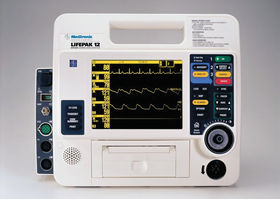
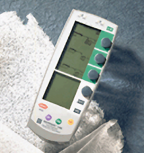
Rapid defibrillation can be performed using a manual device or an automatic device (see Fig 35-21). Manual defibrillators require healthcare providers to interpret cardiac rhythms, determine the need for a shock and deliver a shock. An automatic external defibrillator (AED) is a defibrillator that has rhythm detection capability and the ability to advise the operator to deliver a shock using hands-free defibrillator pads. Proficiency in use of the AED is incorporated in the basic life support (BLS) course for healthcare providers.7 Nurses should be familiar with the operation of the type of defibrillator that is used in the clinical setting.
The following general steps are taken for defibrillation: (1) CPR should be in progress if the defibrillator is not immediately available; (2) the defibrillator should be turned on and the proper energy level selected; and (3) the synchroniser switch should be turned off (see below). Conductive material (e.g. defibrillator gel pads) is applied to the chest; one to the right of the sternum just below the clavicle and the other to the left of the apex. The defibrillator is charged by a button on the defibrillator or the paddles. The paddles are placed on the chest wall over the conductive material (see Fig 35-22). The operator calls and looks to see that everyone is ‘all clear’ to ensure that personnel are not touching the patient or the bed at the time of discharge. The charge is delivered by depressing buttons on both paddles simultaneously.
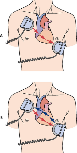
Figure 35-22 Paddle placement and current flow in A, monophasic defibrillation and B, biphasic defibrillation.
Hands-free, multifunction defibrillator pads are available and these are placed on the chest as described above. Cables from the pads are connected to the defibrillator. The defibrillator is charged and discharged by the operator using buttons on the defibrillator. It is still essential that the operator ensures that all personnel are clear before the defibrillator is discharged.
Synchronised cardioversion
Synchronised cardioversion is the therapy of choice for patients with haemodynamically unstable ventricular or supraventricular tachyarrhythmias. A synchronised circuit in the defibrillator is used to deliver a countershock that is programmed to occur on the R wave of the QRS complex of the ECG. The synchroniser switch must be turned on when cardioversion is planned.
The procedure for synchronised cardioversion is the same as for defibrillation with the following exceptions. If synchronised cardioversion is done on a non-emergency basis (i.e. the patient is awake and haemodynamically stable), the patient is sedated (e.g. IV midazolam) before the procedure. Strict attention to maintenance of a patent airway is important in this situation. When a patient with supraventricular tachycardia or VT with a pulse is haemodynamically unstable, synchronised cardioversion is performed as quickly as possible. The energy needed for synchronised cardioversion is generally less than the energy needed for defibrillation. Energy levels are started at 50 J on a monophasic defibrillator and increased (e.g. 100 J, 200 J) if needed.
Implantable cardioverter-defibrillator
The implantable cardioverter-defibrillator (ICD) is an important technology for patients who have: (1) survived SCD; (2) spontaneous sustained VT; (3) syncope with inducible ventricular tachycardia/fibrillation during EPSs; and (4) high risk of future life-threatening arrhythmias (e.g. cardiomyopathy). Use of the ICD has significantly decreased cardiac mortality rates in these patients and has added a new dimension to the management of life-threatening arrhythmias and the prevention of SCD.20
The ICD consists of a lead system placed via a subclavian vein to the endocardium. A battery-powered pulse generator is implanted subcutaneously, usually over the pectoral muscle on the patient’s non-dominant side. The pulse generator is similar in size to a pacemaker. The newest systems are single-lead systems instead of previous multi-lead or patch systems (see Fig 35-23). The ICD sensing system monitors the HR and rhythm and identifies ventricular tachycardia or ventricular fibrillation. Approximately 25 seconds after the sensing system detects a lethal arrhythmia, the defibrillating mechanism delivers a 25-J or less shock to the patient’s heart. If the first shock is unsuccessful, the generator recycles and can continue to deliver shocks.
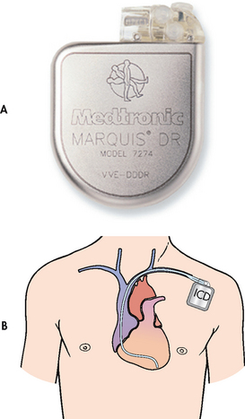
Figure 35-23 A, The implantable cardioverter-defibrillator (ICD) pulse generator from Medtronic. B, The ICD is placed in a subcutaneous pocket over the pectoralis muscle. A single-lead system is placed transvenously from the pulse generator to the endocardium. The single lead detects arrhythmias and delivers an electrical shock to the heart muscle.
In addition to defibrillation capabilities, ICDs are equipped with anti-tachycardia and anti-bradycardia pacemakers. These sophisticated devices use arrhythmia algorithms that detect arrhythmias and determine the appropriate programmed response. The devices can initiate overdrive pacing of supraventricular and ventricular tachycardias, sparing the patient painful defibrillator shocks. They also provide back-up pacing for bradyarrhythmias that may occur after defibrillation discharges. Pre- and postprocedure nursing care of the patient undergoing ICD placement is similar to the care of a patient undergoing permanent pacemaker implantation.
Education of the patient who is receiving an ICD is of extreme importance. The patient will experience a variety of emotions, including fear of body image change, fear of recurrent arrhythmias, expectation of pain with ICD discharge (described as a feeling of a blow to the chest) and anxiety about going home. Box 35-4 describes the teaching guidelines for patients and their families. Participation in an ICD support group should be encouraged. Online resources for patients with an ICD include support groups such as implantable.com and the Cardiac Arrest Survivor Network (see Resources on p 938).
PATIENT & FAMILY TEACHING GUIDE
1. Follow-up with doctor for inspection of ICD insertion site and routine interrogation of the ICD.
2. Report any signs of infection at incision site (e.g. redness, swelling, drainage) or fever to your doctor immediately.
3. Keep incision dry for 4 days after insertion.
4. Avoid lifting arm on ICD side above shoulder until approved by your doctor.
5. Discuss resuming sexual activity with your doctor. It is usually safe to resume sexual activity once your incision is healed.
6. Avoid driving until cleared by your doctor. This decision is usually based on the ongoing presence of arrhythmias, the frequency of ICD firings, your overall health and local laws regarding drivers with ICDs.
7. Avoid direct blows to ICD site.
8. Avoid large magnets and strong electromagnetic fields because these may interfere with the device.
9. Never have a magnetic resonance imaging (MRI) scan.
10. When travelling, inform airport security of the presence of the ICD because it may set off the metal detector. If a hand-held screening wand is used, it should not be placed directly over the ICD.
11. If your ICD fires, call your doctor immediately.
12. If your ICD fires and you do not feel well, call the nearest emergency medical service.
13. If your ICD fires more than once, notify your doctor or call the nearest emergency medical service.
14. Wear a medical alert identification or bracelet at all times.
15. Always carry the ICD identification card and a current list of your medications.
16. Ensure family members learn cardiopulmonary resuscitation.
PACEMAKERS
The artificial cardiac pacemaker is an electronic device used to pace the heart when the normal conduction pathway is damaged or diseased. The basic pacing circuit consists of a power source (battery-powered pulse generator), one or more conducting leads (pacing leads) and the myocardium. The electrical signal (stimulus) travels from the pacemaker, through the leads, to the wall of the myocardium. The myocardium is ‘captured’ and stimulated to contract (see Fig 35-24).
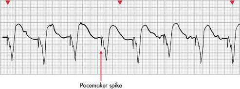
Figure 35-24 Ventricular capture (depolarisation) secondary to signal (pacemaker spike) from pacemaker lead in the right ventricle.
Recent advances in technology have been applied extensively to pacemakers. This has resulted in sophisticated, non-invasive, programmable single- and dual-chambered pacemakers with specialised circuits. Pacemakers have been developed that are more physiologically accurate, pacing the atrium and one or both of the ventricles.20 Pacemakers were initially indicated for symptomatic bradyarrhythmias. However, advances now include anti-tachycardia and overdrive pacing. Anti-tachycardia pacing involves the delivery of a stimulus to the ventricle to terminate tachyarrhythmias (e.g. VT). Overdrive pacing involves pacing the atrium at rates of 200–500 impulses per minute in an attempt to terminate atrial tachycardias (e.g. atrial flutter, atrial fibrillation). Multiple other indications for pacemakers have evolved. For more detailed information on pacemaker therapy, refer to dedicated texts on this topic.1
A permanent pacemaker is one that is implanted totally within the body. The power source is implanted subcutaneously, usually over the pectoral muscle on the patient’s non-dominant side. It is attached to pacing leads, which are threaded transvenously to the right atrium and one or both ventricles. Indications for the insertion of a permanent pacemaker are listed in Box 35-5.
A specialised type of cardiac pacing has been developed for the management of HF. More than 50% of patients with HF have intraventricular conduction delays causing abnormal ventricular activation and contraction and subsequent asynchrony between the right and left ventricles. This can result in reduced systolic function, pump inefficiency and worsened HF. Cardiac resynchronisation therapy (CRT) is a pacing technique that resynchronises the cardiac cycle by pacing both ventricles, thus promoting improvement in ventricular function. Several devices are available that have combined CRT with an ICD for maximum therapy. (HF is discussed in Ch 34.)
Temporary pacemaker
A temporary pacemaker is one that has the power source outside the body (see Fig 35-25). There are three types of temporary pacemakers: transvenous, epicardial and transcutaneous. Indications for temporary pacing are listed in Box 35-6.
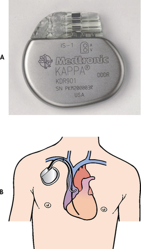
Figure 35-25 A, A dual-chamber rate-responsive pacemaker from Medtronic, designed to treat patients with chronic heart problems in which the heart beats too slowly to adequately support the body’s circulation needs. B, Pacing leads in both the atrium and the ventricle enable a dual-chamber pacemaker to sense and pace in both heart chambers.
BOX 35-6 Indications for temporary pacing*
• Maintenance of adequate HR and rhythm during special circumstances, such as surgery and postoperative recovery, cardiac catheterisation or coronary angioplasty, during drug therapy that may cause bradycardia and before implantation of a permanent pacemaker
• As prophylaxis after open heart surgery
• Acute anterior MI with second-degree or third-degree AV block or bundle branch block
• Acute inferior MI with symptomatic bradycardia and AV block
• Electrophysiology studies to evaluate patient with bradyarrhythmias and tachyarrhythmias
AV, atrioventricular; HR, heart rate; MI, myocardial infarction.
*This table lists common indications, but is not all-inclusive.
A transvenous pacemaker consists of a lead or leads that are threaded transvenously to the right atrium and/or right ventricle and attached to the external power source (see Fig 35-26). Most temporary transvenous pacemakers are inserted in critical care units in emergency situations. They are used until a permanent pacemaker can be inserted or the underlying cause of the arrhythmia has been resolved.
Epicardial pacing is achieved by attaching an atrial and ventricular pacing lead to the epicardium during heart surgery (see Fig 35-27). The leads are passed through the chest wall and attached to the external power source. Epicardial pacing leads are placed prophylactically should any bradyarrhythmias or tachyarrhythmias occur postoperatively.
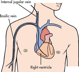
Figure 35-27 Temporary transvenous pacemaker catheter insertion. A single lead is positioned in the right ventricle.
A transcutaneous pacemaker (TCP) is used to provide adequate HR and rhythm to the patient in an emergency situation (see Fig 35-28). Placement of the TCP is a non-invasive procedure that is used temporarily until a transvenous pacemaker can be inserted or until more definitive therapy is available. The TCP consists of a power source and a rate- and voltage-control device that is attached to two large, multifunction electrode pads. One pad is positioned on the anterior part of the chest, usually on the V2 or V5 lead position, and the other pad is placed on the back between the spine and the left scapula at the level of the heart (see Fig 35-28).
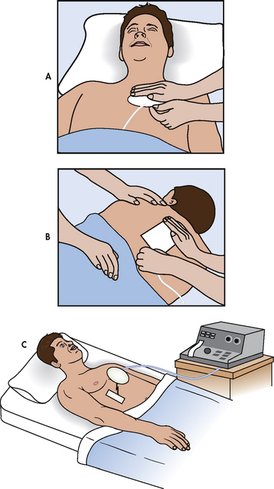
Figure 35-28 Transcutaneous pacemaker. Pacing electrodes are placed on the patient’s anterior, A, and posterior, B, chest walls and attached to an external pacing unit, C.
Before initiating TCP therapy, it is important to tell the patient what to expect. The uncomfortable muscle contractions that the pacemaker creates when the current passes through the chest wall should be explained. The patient should be reassured that the therapy is temporary and that every effort will be made to replace the TCP with a transvenous pacemaker as soon as possible. Whenever possible, analgesia should be provided.
Patient Monitoring
Patients with temporary or permanent pacemakers will be ECG monitored to evaluate the status of the pacemaker. Pacemaker malfunction is primarily manifested by a failure to sense or a failure to capture. Failure to sense occurs when the pacemaker fails to recognise spontaneous atrial or ventricular activity and it fires inappropriately. Failure to sense may be caused by pacer lead damage, battery failure or dislodgement of the electrode. Failure to capture occurs when the electrical charge to the myocardium is insufficient to produce atrial or ventricular contraction. Failure to capture may be caused by pacer lead damage, battery failure, dislodgement of the electrode or fibrosis at the electrode tip.
Complications of invasive temporary (i.e. transvenous) or permanent pacemaker insertion include infection and haematoma formation at the site of insertion of the pacemaker power source or leads, pneumothorax, failure to sense or capture with possible symptomatic bradycardia, perforation of the atrial or ventricular septum by the pacing lead and the appearance of ‘end-of-life’ battery parameters on testing the pacemaker.
Several measures can be taken to prevent or assess for complications and include prophylactic IV antibiotic therapy before and after insertion, post-insertion chest X-ray to check lead placement and to rule out the presence of a pneumothorax, careful observation of the insertion site and continuous ECG monitoring of the patient’s rhythm. After pacemaker insertion, the patient is permitted out of bed once stable. Arm and shoulder activity is limited to prevent dislodgement of the newly implanted pacing leads. The insertion site should be observed for signs of bleeding and to check that the incision is intact. Any temperature elevation should be noted and pain at the insertion site should be treated. Most patients are discharged the next day if stable.
The nurse must provide patient teaching in addition to observation for complications after pacemaker insertion. The patient with a newly implanted pacemaker may have questions about activity restrictions and fears concerning body image after the procedure. The goal of pacemaker therapy should be to enhance physiological functioning and quality of life. This should be emphasised to the patient and the nurse should give specific advice on activity restrictions. Patient and family teaching for the patient with a pacemaker is outlined in Box 35-7.
PATIENT & FAMILY TEACHING GUIDE
1. Maintain follow-up care with your healthcare provider to check the pacemaker site and begin regular pacemaker function checks.
2. Report any signs of infection at incision site (e.g. redness, swelling, drainage) or fever to your healthcare provider immediately.
3. Keep incision dry for 4 days after implantation.
4. Avoid lifting arm on pacemaker side above shoulder until approved by your healthcare provider.
5. Avoid direct blows to pacemaker site.
6. Avoid close proximity to high-output electrical generators or large magnets such as an MRI scanner. These devices can interfere with the function of the pacemaker.
7. Microwave ovens are safe to use and do not interfere with pacemaker function.
8. Travel without restrictions is allowed. The small metal case of an implanted pacemaker rarely sets off an airport security alarm.
9. Monitor pulse and inform healthcare provider if it drops below predetermined rate.
10. Carry pacemaker information card at all times.
11. Wear a medical alert identification or bracelet at all times.
After discharge, pacemaker function is checked on a regular basis. This can include outpatient visits to a pacemaker interrogator/programmer or home monitoring using telephone transmitter devices. Another method to evaluate pacemaker performance is non-invasive program stimulation, which is done on an outpatient basis in the electrophysiology laboratory.
RADIOFREQUENCY CATHETER ABLATION THERAPY
Radiofrequency catheter ablation therapy is a relatively new development in the area of antiarrhythmia therapy. Radiofrequency energy (produced by a low-voltage, high-frequency form of electrical energy) is used to ‘burn’ or ablate areas of the conduction system as definitive treatment of tachyarrhythmias.
Ablation therapy is done after an EPS has identified the source of the arrhythmia. An electrode-tipped ablation catheter is used to ‘burn’ or ablate accessory pathways or ectopic sites in the atria, AV node and ventricles. Catheter ablation is considered the non-pharmacological treatment of choice for AV nodal re-entrant tachycardia, for re-entrant tachycardia related to accessory bypass tracts and to control the ventricular response of certain tachyarrhythmias. In some cases of uncontrolled ventricular response in atrial fibrillation or flutter that is unresponsive to medical therapy, complete ablation of the AV node or bundle of His may be performed. When this is done, the patient must have a permanent pacemaker inserted at the same time.15
The ablation procedure is a successful therapy with a low complication rate. Care of the patient following ablation therapy is similar to that of a patient undergoing cardiac catheterisation (see Ch 33).
ECG changes associated with acute coronary syndrome
The 12-lead ECG is the primary diagnostic tool used to evaluate patients presenting with ACS. Many treatment decisions are directed by the ECG changes that occur with ACS. These definitive changes are in response to ischaemia, injury or infarction of myocardial cells and will be seen in the leads that face the area of involvement (see Fig 35-29). Reciprocal (opposite) ECG changes will often be seen in the leads facing opposite the area involved in ACS. Additionally, the pattern of ECG changes will provide information on the coronary artery involved in ACS (see Table 35-6).
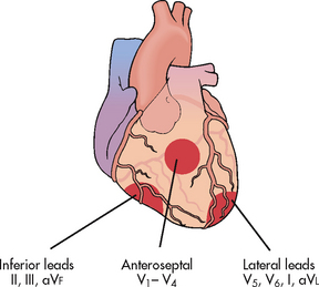
Figure 35-29 Definitive ECG changes occur in leads that face the area of ischaemia, injury or infarction. Reciprocal changes may occur in leads facing opposite the area of ischaemia, injury or infarction.
ISCHAEMIA
Typical ECG changes that are seen in myocardial ischaemia include ST segment depression and/or T wave inversion (see Fig 35-30, A). ST segment depression is significant if it is at least 1 mm (one small box) below the isoelectric line (see Fig 35-6). The isoelectric line is flat and represents those normal times in the cardiac cycle when the ECG is not recording any electrical activity in the heart. These times are seen following the P wave, the ST segment and from the end of the T wave to the start of the next P wave (see Fig 35-10). Depression in the ST segment and/or T wave inversion occurs in response to the electrical disturbance in the myocardial cells due to an inadequate supply of blood and oxygen. Once treated (adequate blood flow is restored), the ECG changes will resolve and the ECG will return to the patient’s baseline. (See Ch 33 for a complete discussion of ACS.)
INJURY AND INFARCTION
Myocardial injury represents a worsening stage of ischaemia that is potentially reversible but may evolve to infarction (necrosis) of myocardial cells. The typical ECG change seen during injury is ST segment elevation. ST segment elevation is significant if it is at least 1 mm above the isoelectric line (see Fig 35-30, B). If treatment is prompt and effective, it is possible to restore oxygen to the myocardium and avoid infarction. This will be confirmed by the absence of serum cardiac markers. If serum cardiac markers are present, infarction has occurred and is referred to as an ST segment elevation MI (STEMI).
In addition to ST segment elevation, a pathological Q wave may be seen on the ECG with infarction (see Fig 35-30, C). A physiological Q wave is the first negative deflection (wave) following the P wave (see Fig 35-10). It is normally very small and narrow (<0.04 seconds in duration). A pathological Q wave that may develop during infarction will be deep and greater than 0.03 seconds in duration. If it does appear, it indicates that at least half the thickness of the heart wall is involved and is referred to as a Q-wave MI.8 The pathological Q wave may be present on the ECG indefinitely.
T wave inversion related to infarction occurs within hours following an infarction and may persist for months. The ECG changes seen in injury and infarction reflect electrical disturbances in the myocardial cells due to a prolonged lack of blood and oxygen leading to necrosis (see Fig 35-31).
Syncope
Syncope, a brief lapse in consciousness accompanied by a loss in postural tone (fainting), is a common diagnosis of patients coming into the emergency department and hospital. The causes of syncope can be categorised as cardiovascular or non-cardiovascular. The most common cardiovascular causes of syncope include: (1) neurocardiogenic syncope or ‘vasovagal’ syncope (e.g. carotid sinus sensitivity); and (2) primary cardiac arrhythmias (e.g. tachycardias, bradycardias). Others causes can be related to prosthetic valve malfunction, pulmonary emboli, aortic dissection and hypertrophic cardiomyopathy. Non-cardiovascular causes are varied and can include hypoglycaemia, hysteria, unwitnessed seizure and vertebrobasilar transient ischaemic attack.8
A diagnostic examination for the patient with syncope from a suspected cardiac cause begins with ruling out structural and/or ischaemic heart disease. This is done with echocardiography and stress testing. In the older patient who is more likely to have ischaemic and structural heart disease, an EPS is used to diagnose atrial and ventricular tachyarrhythmias, as well as conduction system disease causing bradyarrhythmias, all of which can cause syncope. These problems can be treated with antiarrhythmia drug therapy, pacemakers, ICDs and/or catheter ablation therapy.
In patients without structural heart disease or in whom EPS testing is not diagnostic, head-upright tilt table testing may be performed. Normally, an upright position results in gravity displacing 300–800 mL of blood to the lower extremities. Specialised nerve fibres called mechanoreceptors are located throughout the vascular system. These receptors respond to the increased blood volume by initiating a reflex increase in sympathetic stimulation and a decrease in parasympathetic output. The end results are a slight increase in HR and diastolic BP and a slight decrease in systolic BP. In neurocardiogenic syncope, the increase in venous pooling that occurs in the upright position reduces venous return to the heart. This results in a sudden, compensatory increase in ventricular contraction. This is misinterpreted by the brain as a hypertensive state and consequently sympathetic stimulation is withdrawn. This produces a paradoxical vasodilation and bradycardia (vasovagal response). The end results are bradycardia, hypotension, cerebral hypoperfusion and syncope.
In the upright tilt table test, the patient is placed on a table supported by a belt across the torso and feet. Baseline ECG, BP and HR are obtained in the horizontal position. Next, the table is tilted 60–80° and the patient is maintained in this upright position for 20–60 minutes. ECG and HR are recorded continuously and BP is measured every 3 minutes throughout the test. In healthy individuals, venous pooling activates the mechanoreceptors, resulting in the normal response described above. If the patient’s BP and HR responses are abnormal and clinical symptoms are reproduced (e.g. faintness), the test is considered positive. If after 30 minutes there is no response, the table is returned to the horizontal position and an intravenous infusion of low-dose isoproterenol may be started in an attempt to provoke a response. Neurocardiogenic syncope that recurs frequently and interferes with normal activities can be treated with a variety of drugs (e.g. metoprolol).
Other diagnostic tests for syncope include various recording devices. Holter monitors and event monitors are used and are discussed in this chapter and Chapter 32. A subcutaneously implanted loop-recording device can also be used to record the ECG during pre-syncopal and syncopal events. The device can be interrogated after a syncopal event in order to determine the ECG rhythm at the time of the event. For patients with a cardiovascular cause of syncope, the 1-year mortality rate can be as high as 30%.8
CASE STUDY
Patient profile
Jim Maniolis, a 68-year-old retired postal worker, was admitted to the telemetry unit with a diagnosis of acute decompensated HF. He experienced a cardiac arrest (pulseless ventricular tachycardia) and was successfully defibrillated after one shock. He has been transferred to the coronary care unit. He is awake but lethargic and responds appropriately to questions.
CRITICAL THINKING QUESTIONS
1. Why is this patient at risk of sudden cardiac death?
2. Explain the rationale for using amiodarone after cardiac arrest.
3. What methods may be used to assess the effectiveness of the antiarrhythmia therapy?
4. Interpret the rhythm strip and explain the significance of the other diagnostic studies.
5. Would this patient be a candidate for an implantable cardioverter-debrillator? Why or why not?
6. Based on the assessment data provided, write one or more priority nursing diagnoses.
1. A patient admitted with acute coronary syndrome (ACS) has continuous electrocardiographic (ECG) monitoring. An examination of the rhythm strip reveals the following characteristics: atrial rate—74 beats/min and regular; ventricular rate—62 beats/min and irregular; P wave—normal shape; PR interval—lengthens progressively until a P wave is not conducted; QRS—normal shape. Nursing management would involve:
2. The nurse is monitoring the ECG of a patient admitted with ACS. Which of the following ECG characteristics would be most suggestive of ischaemia?
3. The ECG monitor of a patient in the cardiac care unit following a myocardial infarction indicates ventricular bigeminy. The nurse anticipates:
4. The nurse prepares a patient for synchronised cardioversion knowing that cardioversion differs from defibrillation in that:
5. When providing discharge instructions to a patient with a new permanent pacemaker, the nurse teaches the patient to:
6. The nurse plans care for the patient with an implantable cardioverter-defibrillator based on the knowledge that:
7. Important teaching for the patient scheduled for a diagnostic electrophysiological study includes explaining that:
1 Atwood S, Stanton C, Storey-Davenport J. Introduction to basic cardiac dysrhythmias, 3rd edn. St Louis: Mosby, 2009.
2 Huszar RJ. Basic dysrhythmias: interpretation and management, 4th edn. St Louis: Mosby, 2010.
3 American Association of Critical-Care Nurses. Core curriculum for progressive care nurses. St Louis: Saunders, 2010.
4 Craft J, Gordon C, Tiziani A. Understanding pathophysiology. Sydney: Elsevier, 2011.
5 American Association of Critical-Care Nurses. AACN practice alert: ST segment monitoring. Aliso Viejo, CA: American Association of Critical-Care Nurses, 2009.
6 American Association of Critical-Care Nurses. AACN practice alert: dysrhythmia monitoring. Aliso Viejo, CA: American Association of Critical-Care Nurses, 2008.
7 American Heart Association. Handbook of emergency cardiovascular care for healthcare providers. Dallas: American Heart Association, 2008.
8 Moser D, Riegel B. Cardiac nursing: a companion to Braunwald’s heart disease. St Louis: Saunders/Elsevier, 2008.
9 Greenberg ML, Chandrakantan A. Radiofrequency catheter ablation. Available at www.emedicine.com/med/topic2957.htm, 2010. accessed 7 October 2010.
10 National Heart Foundation of Australia. Atrial fibrillation information sheets. Available at www.heartfoundation.org.au/Heart_Information/Heart_Conditions/Atrial_Fibrillation/Pages/default.aspx, 2010. accessed 1 September 2010.
11 Lip GY, Rudolf M. The new NICE guideline on atrial fibrillation management. Heart. 2007;9(1):23. Updated March 2010. Available at http://guidance.nice.org.uk/CG36/NICEGuidance/pdf/English accessed 27 December 2010.
12 Rocca JD. Responding to atrial fibrillation. Nurs Crit Care. 2009;4:5.
13 Knight BP, Gersh BJ, Carlson MD, et al. American Heart Association Council on Clinical Cardiology (Subcommittee on Electrocardiography and Arrhythmias); Quality of Care and Outcomes Research Interdisciplinary Working Group; Heart Rhythm Society; AHA Writing Group. Circulation. 2005;18(2):240–243. 111
14 Hu CL, Jiang H, Tang QZ, et al. Comparison of rate control and rhythm control in patients with atrial fibrillation after percutaneous mitral balloon valvotomy: a randomised controlled study. Heart. 2006;92(8):1096–1101.
15 Calkins H, Brugada J, Packer DL, et al. Heart Rhythm Society; European Heart Rhythm Association; European Cardiac Arrhythmia Society; American College of Cardiology; American Heart Association; Society of Thoracic Surgeons. HRS/EHRA/ECAS expert consensus statement on catheter and surgical ablation of atrial fibrillation: recommendations for personnel, policy, procedures and follow-up. Europace. 2007;9(6):335–379.
16 Blue Cross Blue Shield. Evidence based guideline maze procedure for atrial fibrillation or flutter. Available at www.bcbsnc.com/assets/services/public/pdfs/medicalpolicy/maze_procedure_for_atrial_fibrillation_or_flutter.pdf, 2006. accessed 27 December 2010.
17 Barber P, Robertson E. Essentials of pharmacology for nurses. Philadelphia: McGraw-Hill, 2009.
18 Hayes DL, Friedman PA. Cardiac pacing, defibrillation and resynchronization: a clinical approach, 2nd edn. Hoboken, NJ: Wiley-Blackwell, 2008.
19 McAlister FA, Ezekowitz J, Dryden DM, et al. Cardiac resynchronization therapy and implantable cardiac defibrillators in left ventricular systolic dysfunction. AHRQ pub no. 07-E009. Rockville, MD: Agency for Healthcare Research and Quality, 2007.
20 Epstein AE, DiMarco JP, Ellenbogen KA, et al. American College of Cardiology/American Heart Association Task Force on Practice Guidelines Writing Committee to Revise the ACC/AHA/NASPE 2002 Guideline Update for Implantation of Cardiac Pacemakers and Antiarrhythmia Devices. J Am Coll Cardiol. 2008;27(51):e1–e62.
Australian Resuscitation Council. www.resus.org.au
Cardiac Arrest Survivor Network. www.early-defib.org/survivors.asp
implantable.com—Pacemaker and Defibrillator Site Index www.implantable.com
New Zealand Resuscitation Council. www.nzrc.org.nz
Additional resources for this chapter are listed in Chapters 33 and 34.

