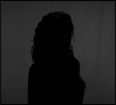
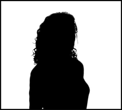
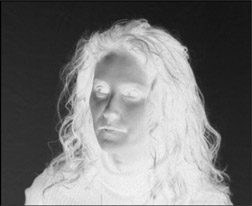
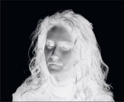
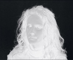
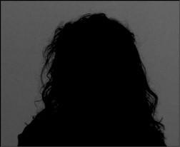
A very important point to keep in mind is that pulling a key from an image, even a perfectly shot greenscreen, is in fact a clever cheat – it is not mathematically valid. It is a fundamentally flawed process that merely appears to work fairly well under most circumstances, so we should not be surprised when things go badly – which they often do. A key is supposed to be an “opacity map” of the target object within the greenscreen image. It is supposed to correctly reflect semi-transparencies at the object’s edges and any other partially transparent regions. Because the keying process is intrinsically flawed, to be a truly effective compositor it is necessary to understand how they work in detail in order to devise effective work-arounds for the inevitable failures.
There are several very high-quality third party keyers on the market such as Ultimatte, Primatte, and Keylight. What they all have in common is that they offer a turn-key solution to greenscreen and bluescreen keying and compositing. You connect the foreground and background plates to the keyer’s node, adjust the internal parameters and voilà! They produce a lovely finished composite. At least that’s what the sales brochure says. As you have no doubt found, compositing a greenscreen is a bit more complex than that. In this book I use the term “greenscreen” to refer to both greenscreens and bluescreens.
More Terminology Turmoil – again, we have confusing terminology in the world of visual effects when it comes to keyers. Many incorrectly refer to all keyers as “chroma keyers”. As we saw in the previous chapter a chroma keyer specifically converts the RGB image into an HSV or HSL image then keys on the chrominance and luminance elements. Most greenscreen keyers are in fact color difference keyers (Keylight, Ultimatte) where they use the difference between the color channels of the backing region to create the key. The one exception is Primatte, which is in fact a very sophisticated three-dimensional chroma keyer, a super-sophisticated version of the little 3D chroma keyer we covered in Chapter 2. In this book I will use the term “keyer” to refer to all of them as it is not helpful to try to label them by their internal approach to keying.
Some keyers work on the principle of creating a sophisticated color difference matte internally, because it is one of the best matte-extraction methods for greenscreens due to its superior edge quality and reasonable semi-transparency characteristics. As mentioned above, both Ultimatte and Keylight are sophisticated color difference keyers. In this section we will see how to “roll your own” color difference mattes as an important exercise to understanding how the keyers work internally.
The importance of this is twofold. First, by understanding how to create a key using the color difference matte process you will be able to “assist” your favorite keyer when it’s having trouble. Second, if you can’t use a keyer either because your software doesn’t have one or it’s having trouble with a greenscreen plate you can always make your own color difference matte. The methods outlined here can be used with any compositing software package or even Adobe Photoshop since they are based on performing a series of simple image processing operations that are universally available.
All keyers support garbage mattes in one form or another. A garbage matte is an external mask that you create to assist a keyer to produce a clean key and they cover two regions – inside the key and outside the key. An “outside” garbage matte is used to clear any noise left in the backing region and an “inside” garbage matte is used to fill in any holes or thin spots in the core of the key. Each keyer has different rules as to how to hook up garbage mattes so read and follow all instructions for your keyer. We have an entire section on creating and using garbage mattes in Chapter 4, Section 4.2: Garbage Mattes.
This first section is about how to extract or “pull” the basic color difference matte using simplistic test plates that provide clean, clear examples. After the basic principles of how the matte extraction works are made clear, the sections that follow are concerned with fixing all the problems that invariably show up in real world mattes.
A greenscreen plate consists of two regions: the object to be keyed (the target) and the backing region (the greenscreen). The whole idea of creating a color difference matte from a greenscreen is that in the green backing region the difference between the primary channel (green) and the two secondary channels (red and blue) is large, but small, zero, or negative in the target. This difference results in a raw matte of some partial density (perhaps 0.2 to 0.4) in the backing region, and zero or near-zero in the target.
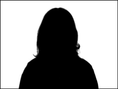
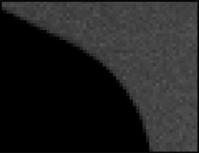
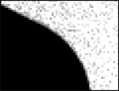
The different densities (brightness) of these two regions can be seen in the raw color difference matte in Figure 3.1. The dark gray partial density derived from the greenscreen backing color is then scaled up to 1.0, a full density white, as shown in the final matte of Figure 3.2. If there are some non-zero pixels in the target region of the matte they are pulled down to zero to get a solid matte. This results in a matte that is a solid black where the target was, and solid white where the backing color was. Some software packages need this reversed, with white for the target and black for the backing, so the final matte can simply be inverted if necessary. Keyers automatically invert this matte internally so their output is the familiar white matte on black background.
The first step in the process is to pull the raw matte. This is done with a couple of simple math operations between the primary (green) and two secondary colors (red and blue), which can be done by any software package using simple math operators. We will look at a simplified version of the process first to get the basic idea, then look at a more realistic case that will reveal the full algorithm. Finally, there will be a messy real world example to ponder.
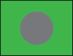
Figure 3.3 is our simplified greenscreen test plate with a gray circle on a green backing. We will refer to the green part of the plate as the backing region since it contains the green backing color, and the gray circle as the target since it is the object we wish to key out for compositing. Note that the target edges are soft, not sharp. This is an important detail because in the real world all edges are actually soft to some degree, and our methods must work well with soft edges. At video resolution a sharp edge may be only one pixel wide, but at feature film resolutions “sharp” edges are typically 3 to 5 pixels wide. Then, of course, there are actual soft edges in film and video such as with motion blur and depth of field (out of focus), plus partial coverage such as fine hair and semi-transparent elements. It is these soft edges and transitions that cause other matte extraction procedures to fail. In fact, it is the color difference matte’s superior ability to cope with these soft transitions and partial transparencies that makes it so important.
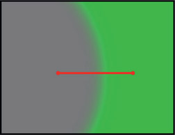
Figure 3.4
Close-up of slice line on the edge transition
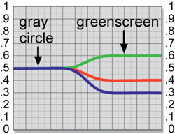
Figure 3.5
Slice graph of gray circle edge transition
Figure 3.3 is our simplified greenscreen plate and Figure 3.4 is a close-up of it with a slice line across it and plotted in Figure 3.5. The slice line starts on the gray circle, crosses the edge transition, then over a piece of the greenscreen. The slice graph in Figure 3.5 graphs the pixel values under the slice line from left to right also. Reading the slice graph from left to right, it first shows that on the gray circle the pixel values are 0.5 0.5 0.5 (a neutral gray), so all 3 lines are on top of each other. Next, the graph transitions towards the greenscreen backing colors, so the RGB values can be seen to diverge. Finally, the samples across the green backing region shows that backing color has RGB values of 0.4 0.6 0.3. So the green backing shows a high green value (0.6), a lower red (0.4) value, and a somewhat lower blue value (0.3) – just what we would expect from a saturated green.
To make our first approximation color difference matte all we have to do is subtract the red channel from the green channel. Examining the slice graph in Figure 3.5, we can see that in the target (the gray circle) the RGB values are all the same, so green minus red will equal 0, or black. However, in the green backing color region the green channel has a value of 0.6 and the red channel has a value of 0.4. In this region, when we subtract green minus red, we will get 0.6 minus 0.4 = 0.2, not 0. In other words, we get a 0 black for the target region and a density of 0.2, a dark gray, for the backing region – the crude beginnings of a simple color difference matte. Expressed mathematically, the raw matte density is:
| Equation 3.1 |
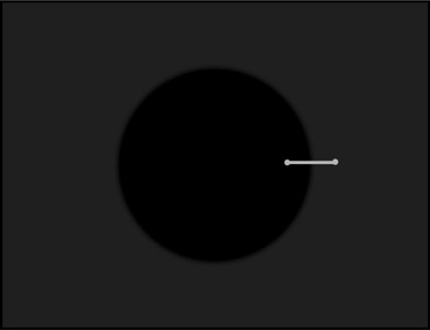
Figure 3.6
Raw color difference matte with slice line
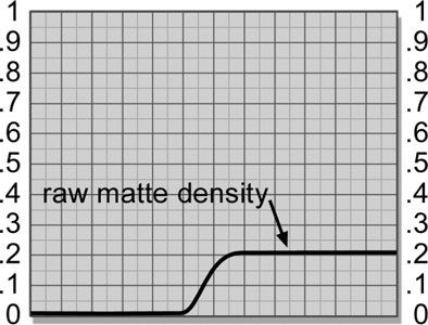
Figure 3.7
Slice graph of raw color difference matte
which reads as “the raw matte density equals the green channel minus the red channel”. The term “density” is used here instead of “brightness” simply because we are talking
about the density of a matte instead of the brightness of an image. For a matte, the item of interest is its density which translates to how transparent it will become in the composite. The raw color difference matte that results from the green minus red math operation is shown in Figure 3.6 with another slice line. We are calling this the “raw” matte because it is the raw matte density produced by the initial color difference math and needs a scaling operation before becoming the final matte. In the green backing region subtracting red from green gave a result of 0.2, which appears as the dark gray region. In the target region the same operation gave a result of 0, which is the black circle in the center. We get two different results from the one equation because of the different pixel values in each region.
In Figure 3.7 the slice graph of the raw matte shows the pixel values where the red slice line is drawn across the raw matte. The raw matte density is 0.2 in the backing region, 0 in the target, and a nice gradual transition between the two regions. This gradual transition is the soft edge matte characteristic that makes the color difference matte so important.

Figure 3.8
Flowgraph of simple raw color difference matte
Figure 3.8 is a flowgraph of the simple G-R raw color difference matte operation. From the greenscreen plate (GS), the red and green channels are connected to a subtract node. The output of the subtract node is the one channel raw color difference matte in Figure 3.6.
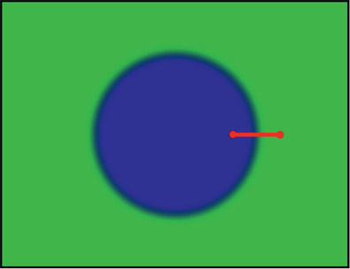
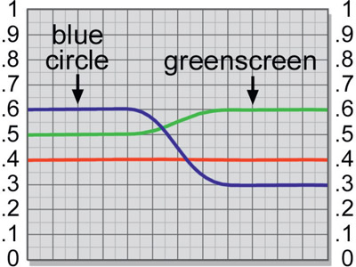
Real images obviously have more complex colors than just gray, so let’s examine a slightly more realistic case of pulling a matte with a more complex target color. Our next test plate will be Figure 3.9, which is a blue circle on a greenscreen backing with a slice graph next to it in Figure 3.10. As you can see by inspecting the slice graph, the target (the blue circle) has an RGB value of 0.4 0.5 0.6, and the same green backing RGB values we had before (0.4 0.6 0.3). Clearly the simple trick of subtracting the red channel from the green channel won’t work in this case because in the target the green channel is greater than the red channel. For the target the simple rule of green minus red (0.5 – 0.4) will result in a matte density of 0.1, a far cry from the desired zero black.
If anything, from this example, we should subtract the blue channel from the green channel. In the target region, green minus blue (0.5 – 0.6) will result in –0.1, a negative number. Since there are no negative pixel values allowed, this is clipped to zero black in the target region, which is good. In the backing region, green minus blue (0.6 – 0.3) gives us a nice raw matte density of 0.3, even better than our first simple example. The problem with simply switching the rule from green minus red to green minus blue is that in the real world the target colors are scattered all over colorspace. In one area of the target red may be dominant, but in another region blue may be dominant. One simple rule might work in one region but not in another. What is needed is a matte extraction rule that adapts to whatever pixel value the target regions happens to have.
Here’s a rule that adapts to those elusive scattered pixel values – the green channel minus whichever is greater, red or blue. Or, put in a more succinct mathematical form:
| Equation 3.1 |
which reads as “the raw matte density equals green minus the maximum of red or blue”. If we inspect the slice graph in Figure 3.10 with this rule in mind, we can see that it will switch on the fly in the edge transition region as we move from the target to the green backing region. In the target, blue is greater than red (max(R,B)), so the raw matte will be green minus blue (0.5 – 0.6) which results in –0.1 which is clipped to zero black. So far so good – we get a nice solid black for our target. Following the slice graph lines in Figure 3.10 further to the right we see the blue pixel values dive under the red pixel values in the edge transition region, so the maximum color channel switches to the red channel as it transitions to the backing region. Here the raw matte density becomes green minus red (0.6 – 0.4) resulting in a density of 0.2. There you have it. An adaptive matte extraction algorithm that switches behavior depending on what the pixel values are.
Figure 3.11 shows the new and improved flowgraph that would create the more sophisticated raw color difference matte. The red and blue channels go to a maximum node that selects whichever pixel is greater between the red and blue channels. The subtract node then subtracts this maximum (R,B) pixel value from the green channel pixels which creates the raw matte. It is called the raw matte at this stage because it is not yet ready to use. Its density, currently only 0.2, needs to be scaled up to full opacity (white, or 1.0) before it can be used in a composite, but we are not ready for that just yet.
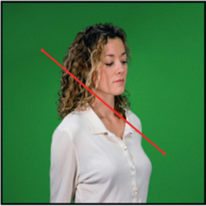
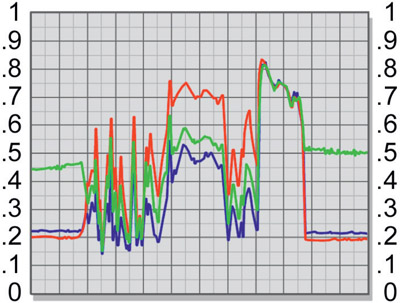
When we pick up a real live action greenscreen image such as Figure 3.12 and graph a slice across the target to the greenscreen (Figure 3.13), we can immediately see some of the differences between real live action and our simple test graphics. First of all, we now have grain, which has the effect of degrading the edges of the matte we are trying to pull. Second, the greenscreen is unevenly lit so the color difference matte will not be uniform across the entire backing region. Third, the target secondary colors (red and blue) cross the green backing color at different values in different locations at the edges, which results in varying widths of the transition region (edges). Fourth, the green channel in the target object can in fact be slightly greater than the other two colors in some areas, resulting in contamination in the target region of the matte. Each of these issues must ultimately be dealt with to create a high quality matte.
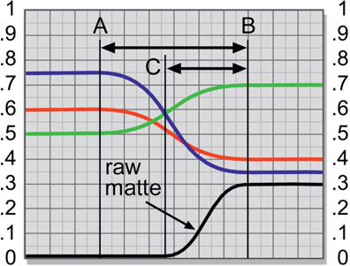
There is another real world issue to be aware of, and that is that the matte normally does not penetrate as deeply into the target as it theoretically should. Figure 3.14 represents a slice graph taken across the boundary between the target and the backing region of a greenscreen – target on the left, green backing on the right – with the resulting raw matte plotted at the bottom of the graph. The two vertical lines
marked A & B mark the true full transition region between the target and background. The target values begin their falloff to become the greenscreen values at line A and don’t become the full backing color until they get to line B.
Theoretically, the new background we are going to composite this element over will also start blending in at line A and transition to 100% background by line B. Obviously, the matte should also start at line A and end at line B. But as you can see, the raw matte does not start until much later: at line C.
The reason for this shortfall is readily apparent by inspecting the RGB values along the slice graph and reminding ourselves of the raw matte equation. Since it subtracts green from the maximum of red or blue, and green is less than both of them until it gets to line C, the raw matte density will be 0 all the way to line C. How much shortfall there is depends on the specific RGB values of the target and backing colors. When the target colors are a neutral gray, the matte does in fact penetrate all the way in and has no shortfall at all. In fact, the less saturated (more gray) a given target color is, the deeper the matte will penetrate. You might be able to figure out why this is so by inspecting the slice graph in Figure 3.4 which shows a gray target blending into a green backing. Just step across the graph from left to right and figure the raw matte density at a few key points and see what you get.
However, for target colors other than neutral grays there is always a matte edge shortfall like the one in Figure 3.14. Further, the amount of shortfall varies all around the edge of the target depending on the local RGB values that blend into the green backing. In other words, line C above shifts back and forth across the transition region depending on the local pixel values, and is everywhere wrong, except for any neutral grays in the target. A second consequence of the raw matte having a sharper edge than the original plate is that the final composite will have a sharper edge than it should. We will see what to do about this and other keying problems in a later chapter.
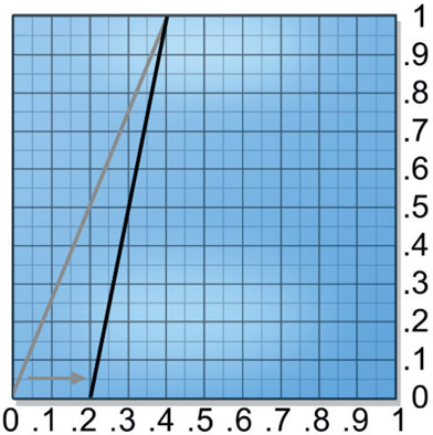
When the raw matte is initially extracted it will not have anywhere near enough density for a final matte. The criteria for the final matte is to get the backing region to 100% white and the target region to zero black. This is done by scaling the density of the raw matte. We have to scale the raw matte density in two directions at once – pulling the whites up and the blacks down – to create the final hicon (high contrast) key which is easily done with a color lookup tool. It is very common to have to scale some dark gray pixels out of the black target region to clear it out since there will often be some colors in the target where the green channel is slightly greater than both of the other two. Let’s see why this is so.
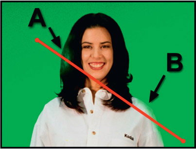
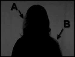
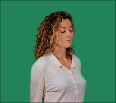
Figure 3.15 illustrates a greenscreen plate with two contaminated regions on the target, A and B. Area A has a green highlight in the hair and there is some green light contamination on the shoulder at area B. The rise in the green channel in these two regions can be seen in the slice graph in Figure 3.16. Since the green channel is noticeably greater than both of the other two channels in these areas it will leave a little raw matte density “residue” in the target region that we do not want. This residual density contamination is clearly visible in the resulting raw matte (marked A and B) shown here in Figure 3.17. The gray residues in the target area are regions of partial transparency and will put “holes” in our target at composite time. They must, therefore, be terminated with prejudice.
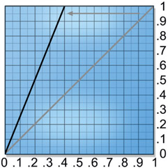
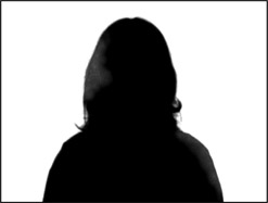
The first step is to scale the raw matte density up to full transparency, which is a density of 1.0 (100% white). Again, the matte can be inverted later if needed. Figure 3.17, the contaminated raw matte extracted from the problem greenscreen in Figure 3.15, shows the raw matte starting point. Move the “white end” (top) of the color lookup graph to the left, as shown in Figure 3.18, a bit at a time, and the raw matte density will get progressively more dense. Stop just as the density gets to a solid 1.0, as shown in Figure 3.19. Be sure to pull up on the whites only as much as necessary and no more to get a solid white because this operation hardens the matte edges, which we want to keep to an absolute minimum. In the process of scaling up the whites, the non-zero black contamination pixels in the target area will also have gotten a bit denser, which we will deal with in a moment. We now have the backing region matte density at 100% white, and are ready to set the target region to zero black.
To set the target region to complete opacity, slide the “black end” (bottom) of the color lookup to the right as shown in Figure 3.20 so it will “pull down” on the blacks. This scales the target contamination in the blacks down to zero and out of the picture like Figure 3.21. This operation is also done a little at a time to find the minimum amount of scaling required to clear out all of the pixels, because it too hardens the edges of the matte. As you pull down on the blacks you may find a few of the white pixels in the backing region have darkened a bit. Go back and touch up the whites just a bit. Bounce between the whites and blacks making small adjustments until you have a solid matte with the least amount of scaling.
It is normal to have to scale the whites up a lot because we are starting with raw matte densities of perhaps 0.2 to 0.5, which will have to be scaled up by a factor of 2 to 5 in order to make a solid white matte. The blacks, however, should only need to be scaled down a little to clear the target to opaque. If the raw matte’s target region has a lot of contamination in it then it will require a lot of scaling to pull the blacks down, which is bad because it hardens the edges too much. Such extreme cases will require heroic efforts to suppress the target pixels to avoid severe scaling of the entire matte. Figure 3.22 shows the ever-evolving flowgraph with a color lookup operation for the scaling added to our growing sequence of operations.

Figure 3.22 Flowgraph with color lookup scaling operation added
WWW Simple keyer.jpg – use this image to try the simple keying techniques outlined above. If you are new to keying you will find it very illuminating.
Some years ago Adobe developed a cute little keyer that works surprisingly well for blue-screens and greenscreens. While you no doubt will normally attack your greenscreens with powerful third-party keyer such as Keylight, I offer you the After Effects keyer as one more arrow in your quiver. Of course, you will have to build it yourself unless you are using After Effects.
We saw earlier that the classical color difference matte generates a raw matte by finding the difference between the backing color and the maximum of two secondary color channels. Adobe has developed a rather different method of generating a raw matte that is very simple and, frankly, works much better than it should since it only uses two channels instead of all three. In principle, the more channels involved in the calculations the more data there is to work with and the better the key. In principle. Let’s walk through it together. The example is with a bluescreen, but it is very straightforward to adapt it to a greenscreen.
You can build your own After Effects keyer with a few operations in just a few minutes. Following is a step-by-step procedure that you can use with any software. Give it a try.
Step 1 – invert the blue channel
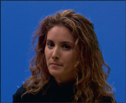
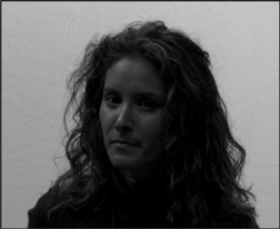
From the bluescreen shown in Figure 3.23, the blue channel is isolated in Figure 3.24. Because the backing region of a bluescreen has a very high blue level in the blue channel, the backing region surrounding the target object is bright while the target itself is dark. This is reversed when the blue channel is inverted as shown in Figure 3.25. The backing region is now dark and the target is light, which is starting to look more matte-like, but we need the backing region to be zero black and the target region to be 100% white.
Step 2 – scale the blacks down
The next step is to scale the blacks down to zero, which clears the backing region as shown in Figure 3.26. However, there are seriously dark regions in the face area of the matte which must be filled in.
Step 3 – screen in the red channel
The red channel is used to fill in these dark regions because there is normally high red content in things like skin and hair. Also, the red channel should be fairly dark in the backing region because that is the greenscreen area. Compare the red channel in Figure 3.27 with the inverted and scaled blue channel in Figure 3.26. The red channel is light in the face exactly where the blue channel is dark. We can use the red channel to fill in this dark region by screening it with the inverted blue channel in Figure 3.26. The results of the screening operation produce the Adobe raw color difference matte shown in Figure 3.28. The face and other regions of the target have now picked up some very helpful brightness from the red channel. Of course, the backing region also picked up some brightness from the red channel’s backing region, but this we can fix.
Step 4 – scale the raw matte
The Adobe raw matte now simply needs to be scaled to a solid black and white to get the results shown in Figure 3.29. As when scaling the classic raw color difference matte, the scaling operation must be done very carefully to avoid over-scaling the matte, which will harden the edges.
By way of comparison, the classic color difference method was used to pull the raw matte shown in Figure 3.30 from the same bluescreen. Compare it to the Adobe raw matte in Figure 3.28 and you can see they produced utterly different results. However, once it is scaled to solid black and white in Figure 3.31 the classic scaled matte is incredibly similar to the Adobe scaled matte in Figure 3.29. But they are not identical.
A flowgraph of the Adobe color difference matte technique is shown in Figure 3.32. The first node, labeled BS, represents the original bluescreen. The blue channel goes to an invert node which correlates to Figure 3.25. The black level is adjusted with the next node to scale its backing region down to zero (Figure 3.26), then the results are screened with the red channel from the original greenscreen image (Figure 3.28). The last node is simply to scale the matte to establish the zero black and 100% white levels of the finished matte shown in Figure 3.29.
Here are some tips on how to vary the After Effects Keyer process that you might find helpful.
- Use the green channel too. After screening the red channel with the inverted blue channel, just lower the blacks to zero again then screen in the green channel. Now scale the resulting raw matte to zero black and 100% white.
- Use color lookups on the blue and red channels to shift their midpoints up or down to clear out problem areas or expand and contract edges.
- The red channel can be added (summed) instead of screened. In some cases it might work better.
- If the target object had a high green content and low red content (such as green plants) then use the green channel instead of the red.
- Use any or all of the preprocessing techniques described in Section 3.5: Preprocessing the Greenscreen to improve the original greenscreen for better matte extraction.
- Of course, this technique is easily adapted to pulling mattes on greenscreens. Just use the green and red channels instead of the blue and red channels.
We now have two powerful color difference matte extraction methods, the After Effects and the classical. So which is better? The truth is, neither. As we saw in the introduction to this chapter the color difference process is a clever cheat that is fundamentally flawed and riddled with artifacts. The only question is whether the inevitable artifacts will create visually noticeable problems in a given composite. Depending on the image content of a given shot, either method could prove superior.
WWW Fig 3–23 bluescreen.tif – use this image to try the After Effects Keyer outlined above. It will be fun.
The entire purpose of the DP (Director of Photography) is to ensure that each scene is properly lit and correctly exposed (oh, yes – fabulous composition and exciting camera angles too!). The greenscreen is to be evenly lit, correctly exposed, and the right color – you know – green! Not cyan, not chartreuse, but green. Somehow this all too often collapses on the set and you will be cheerfully handed poorly lit off-color greenscreen shots and are expected to pull gorgeous mattes and make beautiful composites from these abused plates. As digital compositors we are victims of our own wizardry. Digital effects have become so wondrous that no matter how poorly it is shot on the set, the “civilians” (non-digital types) believe that we can fix anything. The problem is that all too often we can, and as a result we are encouraging bad habits on the part of the film crew.
My standard lecture to the client is: “Poorly lit greenscreens degrade the quality of the matte that can be extracted. Extra work will be required in an attempt to restore some of the lost matte quality, but this will both raise costs, increase the schedule and degrade the results”. Unfortunately, you may never be given the chance to deliver this lecture or supervise the greenscreen shoot. All too often the first time you will know anything about the shot is when the greenscreen frames are handed to you, and then it’s too late. Now you must cope. Poorly lit greenscreens are in fact both the most difficult and the most common problem. There are several different things that can be wrong with the lighting, so each type of problem will be examined in turn, its effect on the resulting matte, and potential workarounds discussed. But it is not a pretty sight.
The consequences of over exposing the greenscreen so it becomes too bright depends on the type of camera used to shoot it. If shot with a regular video camera then it is not high dynamic range and will clip the “hot” region of the greenscreen. This is a very bad “unrecoverable error” because valuable picture content has been irretrievably lost. However, if shot with a digital cinema camera (or film) it will have high dynamic range, and while the greenscreen might be too hot, it will not be clipped so you still have a fighting chance. There is a discussion of digital cinema images in Chapter 15: Digital Images.
Figure 3.33 illustrates what happens when the greenscreen is overexposed with a non-high dynamic range camera. The green channel got clipped in the flat region in the center. The slice graph in Figure 3.34 shows what’s happening. While the red and blue channels peaked around point A, the green channel was clipped flat. This is lost data that cannot be restored. Most importantly, note the difference between the green and red channels at point A in the clipped region, and point B in the normally exposed region. Clipping the green channel has reduced the green-red color difference, so the raw matte values in this region will be much less than in the unclipped regions. Now the matte density will be thinner in the clipped region. The result is that the raw matte must be scaled up even harder which hardens the matte edges and loses fine edge detail like hair. A secondary issue is that the over-lit greenscreen will shower the target with excessive green spill, which is yet another problem to solve.
What to do? The problem with this problem is that critical data has been lost. Not compressed, abused, or shifted in some way that can be recovered, but gone. If the green-screen plate was film transferred to video, then the telecine operation that transferred it to video must be redone, if possible, with a lower exposure. If it was shot in video, then the original video is clipped and you are stuck with what you got.
When the greenscreen is underexposed it will be too dark. After vowing to purchase new batteries for the DP’s light meter, we can examine the deleterious effects of underexpo-sure on the raw color difference matte.
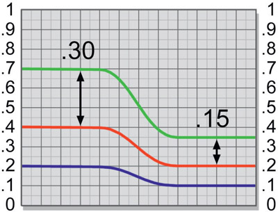
Figure 3.36
Slice graph of normal and underexposed greenscreen
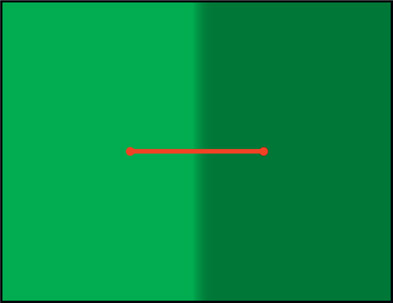
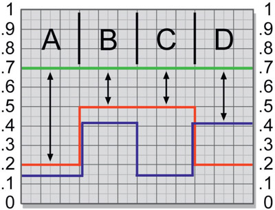
Figure 3.35 shows a greenscreen nicely exposed on the left and underexposed on the right with a slice line across the two regions. As you can see in the slice graph of Figure 3.36, on the correctly exposed (left) side of the greenscreen the color difference between the green and red channels will a healthy 0.30 (0.7 – 0.4), while on the underexposed side the color difference will be an anemic 0.15 (0.35 – 0.2). In other words, the under-exposed side has half the raw matte density of the properly exposed side! The reason is apparent from the slice graph. As the exposure gets lower, the RGB channels not only get lower, but they also move closer together. Moving closer together reduces their difference, hence a lower raw matte density. As a result, the “thinner” raw matte will have to be scaled much harder to achieve full density resulting in harder matte edges and loss of fine edge detail like hair.
Pausing for a lecture, this is a tempting situation to engage in what I call “pushing the problem around”. What I mean by this is putting a fix on a problem that in fact only appears to help, but doesn’t really. Here is an example of “pushing the problem around” in this case: let’s try solving our underexposed greenscreen problem by cleverly increasing the overall brightness of the greenscreen plate before pulling our raw matte. That is to say, we will scale the RGB values up by a factor of 2.0 – and voilà! The raw matte density jumped from 0.15 to 0.30, just like the properly exposed side. We can now scale the new and improved raw matte density by a modest factor of 3.3 to achieve our desired density of 1.0 and go home feeling quit clever. But are we? Let’s take a closer look.
The original raw matte density was 0.15, which will need to be scaled up by a factor of 6.6 to achieve a full density of 1.0. But if we scaled the original RGB channels up by a factor of 2 to get an improved raw matte density of 0.3, then scaled that up by a factor of 3.3 to full density, we have still simply scaled the original density of 0.15 by a factor of 6.6 (2 × 3.3). We have wasted some time, some nodes, and had a fine exercise in the distributive law of multiplication, but we have not helped the situation at all. This is what I mean by “pushing the problem around” but not actually solving it. This is a chronic danger in our type of work, and understanding the principles behind what we are doing will help to avoid such fruitless gyrations. [End of lecture!]
If you are working with video transferred from film there is hope for a rescue here. The film can be re-transferred, but this time have the exposure increased in the telecine. This will increase the brightness of the greenscreen, along with everything else in the scene, of course. However, we can use the brighter version to pull a much better key, then use the original darker version for the composite. This works because the original film has far more data than the resulting telecine video so our second telecine has put the extra film data into the video greenscreen right where we need it. Note that we are NOT pushing the problem around here.
The whole idea of how a greenscreen works is based on a pure, saturated primary color. As we have seen from the math used to pull a color difference matte, to get the maximum raw matte density the green channel must be as far above the red and blue channels as possible, plus the red and blue channels should be at roughly equal levels. This is, by definition, a saturated color. However, in the real world, the red or blue channels may not be very low values. Excessive red or blue channels can cause the green to be “impure” and take on a yellow tint (from high red), a cyan tint (from high blue), or a faded look (from high red and blue). This lack of separation of the color channels dramatically reduces the quality of the matte.
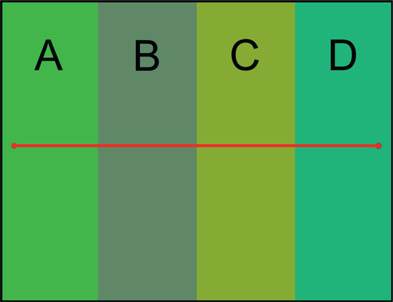
Figure 3.37 shows four side-by-side greenscreen strips, with Figure 3.38 plotting the matching slice graph across all four regions. Region A is a nice saturated green, and its slice graph shows a healthy color difference value (black arrow) that would make a fine raw matte density. Region B is an unsaturated greenscreen example, and its slice graph clearly shows high red and high blue values with a resulting low raw matte density. Region C is too high in red, and since the color difference equation subtracts green from the maximum of the other two channels, red becomes the maximum and the resulting raw matte density is also very low. Region D simply shifts the problem over to the blue channel with similarly poor results.
What can be done? While the situation is dire, it is not hopeless and might be helped by some pre-processing of the greenscreen, an important topic covered in detail later in this chapter. It may be possible to use a subtraction operation to lower one or the other of the offending channels to get a better “spread” between the primary and secondary colors. As this is done it will eventually start to introduce transparency holes in the target object, so go gently. Make a small adjustment then recompute the key and inspect. If things look OK, go a bit more then recompute and check. If some contamination of the target starts to show up in just one region perhaps it can be addressed with one of the pre-processing techniques below. When broad areas start to increase density, you have reached the limits of the process.
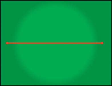
This is both the most common and the most insidious of the bad greenscreen curses. The reason it is the most common is simply because it is very difficult to get the lighting both bright and uniform across a broad surface. The human eye is so darn adaptable that it makes everything look nice and uniformly lit, even when it is not. Cameras are not so accommodating. Standing on the set looking at the greenscreen it looks like a perfectly uniform brightness left to right, top to bottom. But when the captured scene is inspected there is suddenly a hot spot in the center and the corners roll off to a dingy dark green, and now you have to pull a matte on this chromatic aberration. Let’s see what might be done.
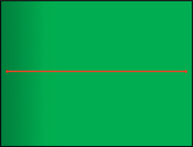
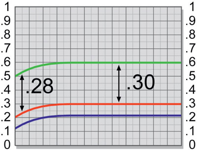
First of all, here’s a rare bit of good news. Even though the greenscreen gets noticeably darker at, say, the left edge, when you pull your color difference matte it will be less uneven than the original film plate! How can this be, you marvel? This is one of the magical virtues of the color difference matte technique compared to, say, chroma key. To see why this is so, let’s refer to Figure 3.39 which shows a greenscreen with a dark left edge and Figure 3.40 which shows the slice graph of the unfortunate greenscreen.
As can be seen in the slice graph, the greenscreen brightness drops off dramatically on the left edge. The RGB values at the left edge of the graph can be seen dropping almost 20% compared to the properly lit region. But look closely at the difference between the red and green channels. All three channels drop together, so their difference does not change as dramatically. In the properly lit region the raw matte density is about 0.30, and in the dark region about 0.28, only a little less. While the green channel dropped off dramatically, so did the red channel. In fact, they largely drop off together, so their difference is only affected slightly. More than any other matte extraction method the color difference matte is fairly forgiving of uneven greenscreens. That is the end of the good news for today, however. Next, we will take a look at how the uneven greenscreen affects the matte, then what might be done about it.
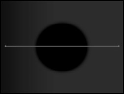
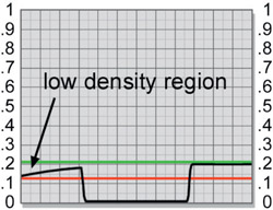
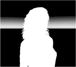
Figure 3.41 shows an unevenly lit greenscreen and target element, both getting darker on the left. Next to it in Figure 3.42 is the resulting uneven raw matte (before scaling) using our standard color difference matte extraction procedure (G – max(R,B)). A low-density region can be seen along the left edge of the raw matte which will become a partially opaque region if we don’t do something about it. The slice graph of the uneven matte in Figure 3.43 shows the lower density in the backing region on the left edge (exaggerated for clarity). There is also a red and a green reference line added to the slice graph.
The green line represents the desired point that would normally be pulled up to 100% white by the scaling operation. If this were done, the backing region at the left edge would remain partially opaque in the process, since it won’t make it to 100% white. We can solve this problem by scaling the matte up harder from the much lower point indicated by the red line until this becomes the 100% white point. But this will clip out some of the edge detail of the matte and harden the edges, neither of which we want to do. What is needed is some way to even up the greenscreen plate, which we shall see shortly.
WWW Uneven greenscreen.jpg – this film scan has some uneven lighting falling off in the corners. Use the simple G – (max(R,B)) technique to pull a raw matte and see how it is affected. Then try your favorite keyer and see how it does.
You can always improve your keyer’s results with some kind of preprocessing of the greenscreen to “set it up” to pull a better key. The basic idea is to perform some operations on the greenscreen plate before the matte is pulled that improves either the raw matte density in the backing region, clears holes in the target region, improves edge characteristics, or all of the above. There are a number of these operations, and which ones to use will depend on the image content with which you are working.
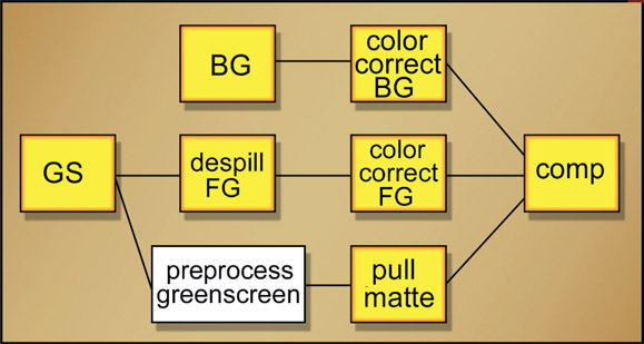
Figure 3.44 shows a flowgraph of how the preprocessing operation fits into the overall sequence of operations. The key point here is that the preprocessed greenscreen is a “mutant” version kept off to the side for the sole purpose of pulling a better matte, but not to be used for the actual composite. The original untouched greenscreen is used for the actual foreground despill, color correction, and final composite. In this section we will explore several preprocessing operations that can help in different circumstances. Which techniques will work on a given shot depends entirely on the actual problems present in the greenscreen plate. You may use one or all of them on a given greenscreen.
Denoise (removing video noise or film grain) is an absolutely fundamental preprocessing technique that must be considered a default operation that is always done before pulling any key. The presence of noise in the image adds noise to the edges of the key. Called “edge chatter”, it shows up in the composite and must be eliminated. Note that film grain and digital noise have entirely different characteristics so your denoise operation needs to be smart enough to be set for the type of grain/noise you are trying to remove. Here we will see why the noise shows up in the edges of our keys. To avoid tediously switching from “grain” to “noise” I will simply use the term “noise” to refer to both.
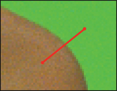
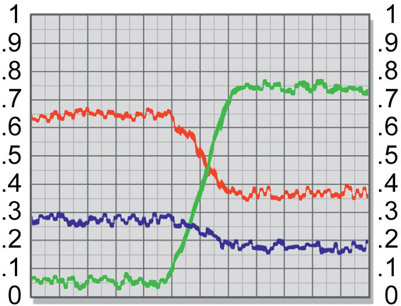
Figure 3.45 is a close-up of a greenscreen plate showing the noise with a slice line crossing the transition region between the target and backing. The noise can be seen in the choppy slice graph in Figure 3.46. This noise is going to show up in the raw matte then, worse yet, scaled up with it to form the final key.
Figure 3.47 represents the raw matte created from the greenscreen close-up in Figure 3.45. As you can see, the image noise has become “embossed” into the raw matte. The nature of the universe is such that the blue channel always has more noise than any other channel. This is true of both film and video. So when working with bluescreen be prepared for noisier mattes.
As mentioned above, the raw matte density must be scaled up from the typical value of 0.2 or 0.3 to a full density value of 1.0, which is a scale factor of 3 to 5. This will obviously also scale up the noise by a factor 3 or 5. Let’s say that the raw matte density was an average of, say, 0.2. We would then scale it up by a factor of 5 to get a density of 1.0. But the 0.2 was an average value, so when the matte is scaled up some of the pixels don’t make it to 100% white. This leaves some speckled contamination in the backing region as shown in the scaled matte in Figure 3.48.
We are therefore forced to scale the brightness up by more than the original factor of 5 to get all the noise out of the backing region. Scaling the matte up more hardens the edges, clobbers fine edge details like hair, and increases the edge chatter. These are the reasons the greenscreen plate must be denoised before pulling a key.
The problem is that all denoise operations also remove fine detail making it look a bit blurry – some more than others – so it behooves you to search for a high quality denoise tool. You must strike a balance between removing enough noise to protect your key, but not so much that you lose important picture detail. If you don’t have any denoise tools then you can filter it use a median filter then do a mix-back of the filtered version with the original plate to minimize the damage. Again, it’s a balancing act.
The blue channel noise affects bluescreens and greenscreens differently. With bluescreens it is the primary color of the matte so all of the matte calculations are based on it. As a result, its excessive noise is embedded into the matte edges, giving bluescreen mattes more edge chatter than greenscreen mattes. A greenscreen matte will have “quieter” edges due to the less noise in the green channel.
Important Imaging Facts:
- Most of the noise is in the blue channel.
- Most of the image detail is in the red and green channels.
By taking advantage of this fortuitous juxtaposition of picture information (if you have to roll your own denoise) the most noise reduction can be achieved with the least loss of matte detail by smoothing just the blue channel.
Greenscreens will often be unevenly lit such that they fall off in brightness from left to right or top to bottom – or both. This has the effect of requiring the raw matte to be scaled up harder resulting in hard edges. Screen leveling is the process of evening up the falloff to be more uniform so the raw matte does not have to be scaled up so hard resulting in kinder, gentler edges. This concept is also very applicable to luma keys as well.
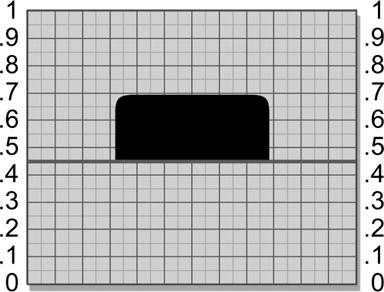
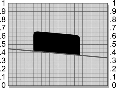
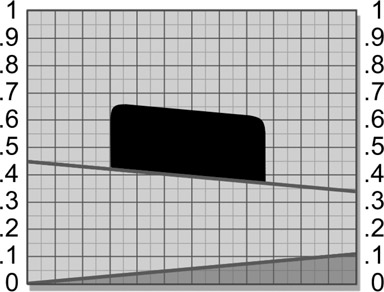
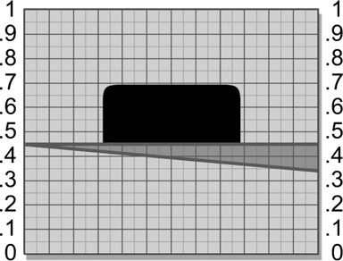
Here is a conceptual model that will help you to visualize how screen leveling works. We can imagine the greenscreen to be a one channel image viewed edge-on in Figure 3.49 as a flat straight line with a “target object” that we want to isolate sitting on it. It would be trivial to cleanly separate the target with a single threshold value, 0.45 in this example. However, Figure 3.50 illustrates the gradient of the greenscreen sloping off to the right.
Trying to separate the target here will be a problem because there is no longer a single threshold value that will work. Whatever value is selected it will either leave some pieces of the target object behind, include pieces of the greenscreen, or both.
But what if we could “straighten up” the greenscreen, making it flat? In Figure 3.51 a gradient is shown at the bottom of the graph pointing in the opposite direction – a “counter-gradient”. If this counter-gradient is summed with (added to) the greenscreen plate, it will raise the low end of the backing and the target object together to restore a “flat” surface like the one in Figure 3.52, which can now be separated with a single threshold value. If the color difference matte is extracted from the “leveled” green-screen, the raw difference matte will now be much more uniform. You cannot use this technique with the raw matte after it is pulled. The reason is that the gradient you add to level out the raw matte would also be added to the zero black region of the target, introducing a partial transparency there. It must be done to the greenscreen plate before pulling the matte.
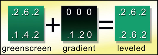
To apply this to a simplified test case, let’s say that we have a greenscreen plate that gets dark from top to bottom. The procedure is to measure the RGB values at the top and bottom, subtract the two sets of numbers, and this will tell us how much the RGB values drop going down the screen. We would then make the counter-gradient that is zero black at the top and whatever value the difference was at the bottom. We would then add the counter-gradient plate to the greenscreen plate to level it out.
An example is shown in Figure 3.53. The left-most square represents a greenscreen plate with RGB values at the top of .2 .6 .2, and at the bottom .1 .4 .2. Subtracting the two sets of RGB numbers, we find that the bottom is RGB .1 .2 .0 darker than the top. We now create a counter-gradient that is black (0 0 0) at the top and .1 .2 .0 at the bottom. Note that the difference between the RGB values will not be the same for all channels, so it
is not a gray gradient but a 3-channel colored one with different values in each channel. When we add these two plates together the new greenscreen will have equal values from top to bottom – it will now be “level”. We can now pull a much cleaner matte.
Since the compensating gradient was green dominant and was also added to the target region, it will slightly raise the green channel in the target region. This will sometimes add a bit of contamination to the target depending on its color composition, but it is well worth the gains of the improved backing uniformity. We have traded the large problem of an uneven greenscreen backing for the much smaller problem of a little possible target contamination resulting in thin spots in the key, which can be addressed with other measures. This is a common strategy in visual effects – converting a problem to a different form that is easier to solve.
Meanwhile, back in the real world, you will not have unevenly lit greenscreens that vary neatly from top to bottom like the little example above. They will vary from top to bottom and left to right and be bright in the center and have a dark spot just to the left of the shoulder of the actor – making a much more complex irregularly “warped” greenscreen. Your software package may or may not have tools suitable for creating these complex gradients. The key is to do what you can to level the screen as much as possible, knowing that whatever you can do will help and that it does not have to be perfect – just better. When it comes to the raw matte density every little bit helps because the raw matte is going to be scaled up by many times, so even a 0.05 improvement could add 10% or 20% improvement to the final results.
WWW Screen leveling.jpg – this cloud picture is clearly on uneven sky backing. Try pulling a luma key on the cloud, then do screen leveling and try again. Better?
As we know, the problem areas in the target region are caused by the green channel climbing above the other two channels in some area. We want a surgical approach that will just alter the afflicted area of the greenscreen in a way that suppresses the problem upstream of the keyer. So ideally, we would just push the green channel down a bit in the problem area, solving the problem without disturbing any other region of the green-screen plate. This is sometimes both possible and easy to do.

Figure 3.54
Flowgraph of chroma key used for local suppression
Referring to the flowgraph in Figure 3.54, create a mask from the original greenscreen plate that covers the problem area using any of the mask generation techniques outlined in Chapter 2: Pulling Keys. Use this mask with a color adjusting tool to lower the green channel under the mask just enough to clear (or reduce to acceptable) the problem area from the target’s key. Perhaps the subject has green eyes, which will obviously have a green component higher than the red and blue in that area. Make a chroma key mask for the eyes and suppress the green a bit. Perhaps there is a dark green kick on some shiny black shoes that also punches holes in the target region of the matte. Mask and suppress.
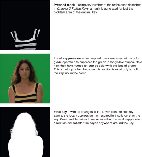
Now let’s take a look at a workflow example of the local suppression technique outlined in Figure 3.55. We will first pull a key on the greenscreen and see where we have trouble. An isolation mask will be generated to use with a color adjustment to lower the green in the problem area then the new key will be generated using exactly the same keyer settings.
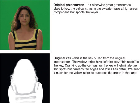
Sometimes the prepped mask above can simply be merged with the original key to “fill in its holes”. However, that will give you a different result than using it to preprocess the greenscreen for the keyer simply because the pixels would be going through different processes.
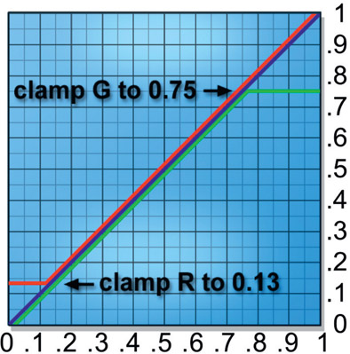
Let’s explore a more sophisticated solution to the problem greenscreen in Figure 3.15, which had the green highlight in the hair and some green spill on the shoulder. Re-examining the slice graph in Figure 3.16, the graph area marked A shows the green channel rising about 0.08 above the red channel, which is the result of the green highlight in the hair. The graph area marked B shows the green channel has risen above the red channel due to the green spill on the shoulder. It has reached a value as high as 0.84 while the average value of the backing green channel is down near 0.5. What we would like to do is shift the color channels so that the green channel is at or below the red channel in these two regions without disturbing any other parts of the picture. We can either move the green channel down or the red channel up. In this case, we can do both.
Referring to the color lookup in Figure 3.56, the red curve has been adjusted to clamp the red channel up to 0.13 so no red pixel can fall below this value. As a result, the red channel in the hair highlight in area A has been “lifted” up to be equal to the green channel, clearing the contamination out of this area of the raw matte. The resulting slice graph in Figure 3.57 shows the new relationship between the red and green channels for area A. Similarly, the problem in area B has been fixed by the same color lookup in Figure 3.56 by putting a clamp on the green channel that limits it to a value of 0.75. This has pulled it down below the red channel, which will clear this area of contamination.

Figure 3.57
Red and green channels clamped by color lookup
Again, we just need to get the green channel below (or nearly below) either the red or blue channels to clear the target matte. This means either lowering the green channel or raising one of the other two. Either one will work. The key is to shift things as little as possible, then check the raw matte for the introduction of any new problems in other areas. Keep in mind that there could be other parts of the picture that also get caught in this “net” which could introduce other problems. Make small changes then check the raw matte.
Here is a nifty technique that you will sometimes be able to use, again, depending on the actual color content of the greenscreen. By simply raising or “lifting” the entire green channel you can increase the raw matte density resulting in a better matte with nicer edges. Starting with the slice graph in Figure 3.58, the difference between the green channel and the maximum of the red and blue channels in the backing region is about 0.3. We can also see that the green channel is everywhere well below both the red and blue channels in the target region. If the green channel were raised up by 0.1 as shown in Figure 3.59 it would increase the raw matte density from 0.3 to 0.4, a whopping 33% increase in raw matte density! As long as it is not raised up so much that it climbs above the red or blue channels, no holes in the target will be introduced. Of course, in the real world you will rarely be able to raise the green channel this much, but every little bit helps.
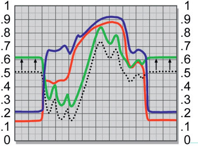
Figure 3.59
Green channel shifted to increase raw matte density
The procedure is to raise the green channel a bit by adding a small value (0.1 in this example) to the green channel, then pull the raw matte again to look for any new contamination in the target. If all seems well, raise the green channel a bit more and check again. Conversely, you can try lowering the red and blue channels by subtracting constant values from them. These techniques can sometimes solve big problems in the matte extraction process, but sometimes at the expense of introducing other problems. The key is an intelligent tradeoff that solves a big, tough problem while only introducing a small, soluble problem. For example, if only a few holes are introduced you can always pound them back down with local suppression techniques or perhaps with a few quick rotos.
In addition to adding or subtracting constants from the individual channels to push the channels apart for better raw mattes you can also scale the individual channels with the color lookup tool. It is perfectly legal to have “creative color lookups” to push the color channels around in selected regions to get the best matte possible. Always keep in mind that the color difference matte extraction works on the simple difference between the green channel and the other two channels, so raising or scaling up the green can increase the difference, but so can scaling down or lowering the red or blue channels. Push them around, see what happens.
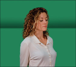
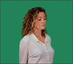
In all my years of compositing visual effects the most awesome technique I have ever encountered is screen correction. It magically replaces the uneven backing region of a greenscreen with a perfectly uniform green color that every keyer will love. Most importantly, it does this without disturbing the edges in the corrected regions. You can see the results of this astonishing technique starting with the backing region defects shown in Figure 3.60 compared to its screen corrected version in Figure 3.61. Which one would you like to key?
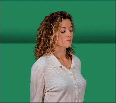
Figure 3.60
Original greenscreen with backing region defects
Invented by Ultimatte, this technique can rescue the most hideous greenscreens and turn them into cooperative creampuffs for your keyer. The procedure is a bit complex, but if you work through it patiently I promise you that it will be well worth the effort.
Note: this procedure should be done in floating point where all negative code values are preserved. While it is possible to do this in an integer-based system, the procedure will have to be adjusted to reclaim all negative numbers because an integer system will clip all negative code values to zero.
Step 1 – pull a soft key on the original greenscreen
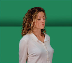
Figure 3.62
Original greenscreen
A “soft key” here means the backing region is not cleared to zero black but the character’s core matte is solid. Sample the backing color for the keyer but do not adjust the backing region. The “contamination” in the backing region with all defects is essential to keep. I use Keylight for this but any keyer will do.
Step 2 – pull the identical soft key on a clean greenscreen

Figure 3.64
Clean greenscreen
You will never be given a true clean greenscreen so you will have to build one using any number of techniques in your compositing program. If you would like some ideas for this check out Section 3.5.6.4: How to Create a Clean Greenscreen. Use a copy of the keyer used in step 1 so its settings will be identical. The resulting keys from step 1 and step 2 here should therefore be identical except for the character.
Step 3 – create the screen correction matte
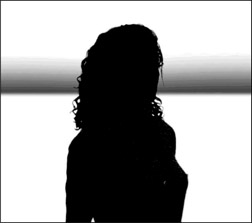
Figure 3.66
Inverted greenscreen soft key
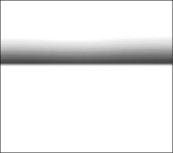
Figure 3.67
Inverted clean greenscreen soft key
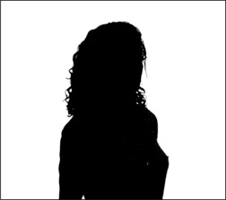
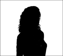
Invert the two soft keys from Figure 3.63 and Figure 3.65 then divide them (yes, divide!) to produce the screen correction matte shown in Figure 3.68. We now have a matte that has the defect removed, but it is a one-channel image in the alpha channel. Convert it to an RGB image because we need to use it to multiply another RGB image shortly. So the screen correction matte must be a 3-channel image.
Step 4 – create the defect map
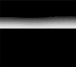
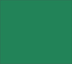
Make a solid plate of green (Figure 3.69) that is the color of the good part of the original greenscreen. This will become the new backing color. Subtract this solid plate from the clean greenscreen in Figure 3.70 (i.e. solid greenscreen minus clean greenscreen) to create the defect map shown in Figure 3.71.
This is critical – the clean greenscreen will have regions that are both lighter and darker than the solid greenscreen so after the subtraction the resulting defect map will contain both positive and negative numbers. Those negative numbers must be preserved and not clamped to zero. Check various pixels in the defect map to confirm that you have preserved them.
The defect map is a map of the differences between the clean greenscreen and the uniform color of the solid greenscreen. When this defect map is summed with the original greenscreen it will correct all the defects in it.
Step 5 – create the correction frame
Multiply the defect map (Figure 3.71) by the screen correction matte (Figure 3.72) to produce the correction frame (Figure 3.73). This holds out the character from the defect map so only the backing region will be corrected leaving the character untouched.
Step 6 – create the final corrected greenscreen
Sum (add) the correction frame (Figure 3.73) with the original greenscreen (Figure 3.74) to create the final corrected green-screen (Figure 3.75). The positive code values in the correction frame will fill in the dark parts of the backing region and the negative code values will bring down the over-bright areas bringing the entire backing region to one solid uniform color. This is the corrected greenscreen that you can now key with your favorite keyer.
Because this procedure is a bit complex here is another view of the entire process in pictographic form.
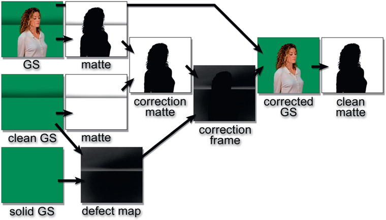
Figure 3.76
Pictographic flowchart of screen correction procedure
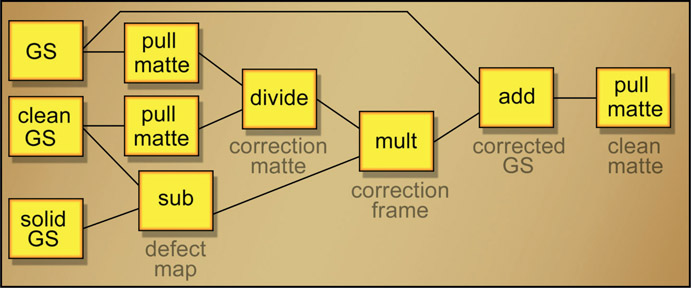
Figure 3.77
Flowgraph of screen correction procedure
For fans of node-based compositing here is a flowgraph of the entire screen correction procedure. Hopefully with all these visual aids you will have no trouble recreating the screen correction process with your compositing software. Again, watch your negative code values. They must be preserved.
The screen correction process and other keying techniques require a clean greenscreen so here is a procedure for making one for a locked off camera shot. The basic idea is to build a single plate that is assembled from the exposed regions of the greenscreen from each frame as the target moves around. This clean greenscreen plate is then used as a held frame for all frames of the shot. Figure 3.78 shows a greenscreen shot with a squirmy kid moving around. Over the length of the shot he reveals 90% of the green-screen so we need to capture all of the exposed greenscreen areas and combine them into a single clean plate.

Figure 3.79
Holdout version of the clip with the target keyed to black
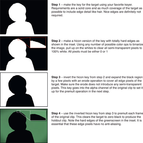
The first step is to prepare the “holdout” version of the clip that has the target keyed out to zero black for the entire length of the clip like the example in Figure 3.79. This is done by creating a key then using the inverted alpha channel to premultiply the original green-screen. The result is that the target is blacked out over the length of the clip leaving just the greenscreen. Here is the step-by-step procedure for creating the blackened version of the clip:
The next step is to accumulate all of the remaining greenscreen areas of the holdout clip from Figure 3.80 into a single plate by performing a maximum operation between each frame of the holdout clip. How this is done varies from software to software, but the process is to max frame 1 with frame 2, then max frame 3 with those results, then max frame 4 with those results, etc. for the length of the clip. At the end of the clip the black area has shrunk to just those areas that were never revealed by the moving target.
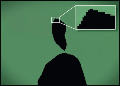
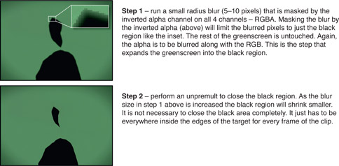
Figure 3.81 shows the results you should get for the RGB channels from maxing all of the holdout frames together. The black region has shrunk to just those areas never revealed by the moving target. Note the hicon edges in the inset. There must be no anti-aliased pixels here. Figure 3.82 shows the results for the alpha channel. Again, no anti-aliased pixels here either. This forms the raw clean plate which then needs to be further processed to shrink the remaining black region somewhat using the “blur and grow” technique from Chapter 2. Figure 3.83 shows the step-by-step procedure:
If there are any pixels from the target remaining on the greenscreens (typically wisps of hair) they will accumulate in the clean plate here. Two solutions – go back to step 3 and expand the black region a bit more to clear them out and/or paint them out with a clone brush on the finished clean plate. Because we are now dealing with a single clean plate such fixes are easy.
If the target is walking across the screen then there is a simplification that can be made by just selecting a few frames to max together rather than the entire clip. Select frames where the target does not overlap the other frames such as where the target is screen left, middle, and right for example.
WWW Keying Frames – this folder contains two greenscreen and two blue-screen frames for your keying enjoyment, to apply the above techniques to even out their non-uniform backing regions.
Now that we know everything there is to know about pulling mattes the next chapter will reveal a number of important techniques for refining those mattes. We will see ways to protect against over-scaling a matte, various filtering operations, plus dilation and erosion operations to adjust the size of the matte and even sculpt the falloff of the edges.
