In this chapter, you will learn how to
• Describe the basic roles of various networked computers
• Discuss network technologies and Ethernet
• Describe the differences between a LAN and a WAN and the importance of TCP/IP
It’s hard to find a computer that’s not connected to a network. Whether you’re talking about a workstation that’s part of a large enterprise network or discussing that smartphone in your pocket, every computer has some form of network connection. CompTIA has added quite a bit of networking coverage to the CompTIA A+ exams.
This chapter dives into networks in detail, especially the underlying hardware and technologies that make up the bulk of networks in today’s homes and businesses. The discussion starts by examining the roles computers play in networking, helping you associate specific names with devices and services you’ve undoubtedly used many times already. The second portion, and the heart of the chapter, focuses on the now-standard network technology used in most networks, regardless of operating system. The final section examines how this network technology looks in a normal workplace.
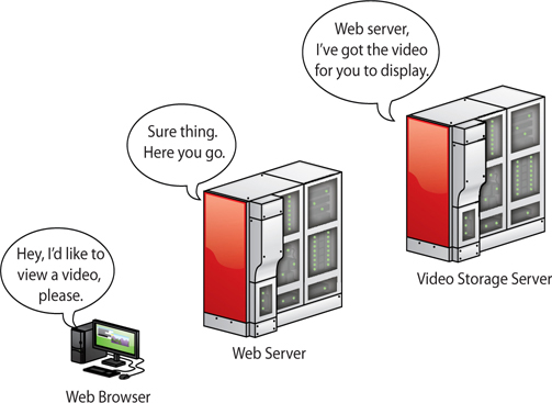
Take a moment to think about what you do on a network. Most of us, when asked, would say, “surf the Internet,” or “watch YouTube videos,” or maybe “print to the printer downstairs.” These are all good reasons to use a network, but what ties them together? In each of these situations, you use your computer (the local host) to access “stuff” stored on a remote host (not your local computer). A host is any computing device connected to a network. So what do remote computers have that you might want (see Figure 20-1)?
Figure 20-1 Accessing remote computers

NOTE Terminology shifts as soon as computing devices network together. Because a computing device can take many forms, not just a PC or workstation, we need a term to define networked devices. A host is any computing device connected to a network. A local host, therefore, refers to what’s in front of you, like your Mac OS X workstation. A remote host refers to some other computing device on the network or reachable beyond the network (more on those later).
Each networked host fulfills a certain role. A remote computer called a Web server stores the files that make up a Web site. The Web server uses server programs to store and share the data. So the role of the Web server is to provide access to Web sites. Two popular Web server programs are Apache HTTP Server and Internet Information Services (IIS). When you access a Web site, your Web browser (likely Internet Explorer, Mozilla Firefox, Google Chrome, or Microsoft Edge) asks the Web server to share the Web page files and then displays them (see Figure 20-2). Because your computer asks for the Web page, we call it the client. That’s the role of the local host in this example. The remote computer that serves the Web site is a server.
Figure 20-2 Accessing a Web page
NOTE Add to this list the many legacy and embedded systems still floating about, performing specific, non-modern tasks.
But what about YouTube? YouTube also uses Web servers, but these Web servers connect to massive video databases. Like a normal Web server, these remote computers share the videos with your client device, but they use special software capable of sending video fast enough that you can watch it without waiting (see Figure 20-3).
Figure 20-3 Accessing a YouTube page
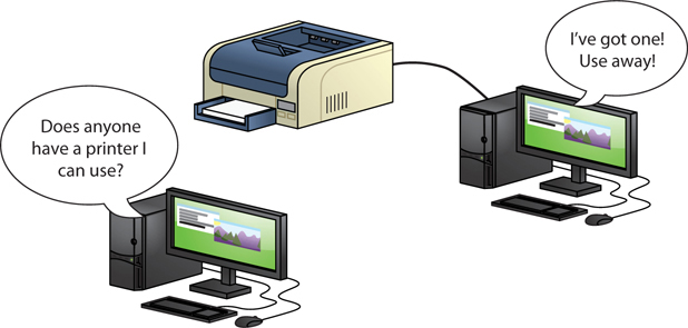
But we don’t need the Internet to share stuff. Figure 20-4 shows a small home network with each computer running Windows. One of the computers on the network has a printer connected via a USB port. This computer has enabled a printer-sharing program built into Windows so that the other computers on the network can use the printer. That computer, therefore, takes on the role of a print server.
Figure 20-4 Sharing a printer in Windows
No matter how big the network, we use networks to share and access stuff. This stuff might be Web pages, videos, printers, folders, e-mail messages, music … what you can share and access is limited only by your ability to find a server program capable of sharing it and a client program that can access it.
Each type of server gets a label that defines its role. A networked host that enables you to access a bunch of files and folders is called a file server. The networked host you use to access e-mail messages? It’s called a mail server. Truth in advertising!
Network people call anything that one computer might share with another a resource. The goal of networking, therefore, is to connect computers so that they can share resources or access other shared resources.
To share and access resources, a network must have the following:
1. Something that defines and standardizes the design and operation of cabling, network cards, and the interconnection of multiple computers
2. An addressing method that enables clients to find servers and enables servers to send data to clients, no matter the size of the network
3. Some method of sharing resources and accessing those shared resources
Let’s look now at the first of these network needs and discuss current industry standards.
When the first network designers sat down at a café to figure out how to get two or more computers to share data and peripherals, they had to write a lot of notes on little white napkins to answer even the most basic questions. The first question was: How? It’s easy to say, “Well, just run a wire between them!” But that doesn’t tell us how the wire works or how the computers connect to the wire. Here are some more big-picture questions:
• How will each computer be identified?
• If two or more computers want to talk at the same time, how do you ensure that all conversations are understood?
• What kind of wire? What gauge? How many wires in the cable? Which wires do what? How long can the cable be? What type of connectors?
Clearly, making a modern network entails a lot more than just stringing up some cable! As you saw a bit earlier, most networks have one or more client machines, devices that request information or services, and a server, the machine that hosts and shares the data. Both clients and servers need network interface controllers (NICs) that define or label the machine on the network. A NIC also breaks files into smaller data units to send across the network and reassembles the units it receives into whole files. You also need some medium for delivering the data units between two or more devices—most often this is a wire that can carry electrical pulses; sometimes it’s radio waves or other wireless methods. Finally, a computer’s operating system has to be able to communicate with its own networking hardware and with other machines on the network. Figure 20-5 shows a typical network layout.
Figure 20-5 A typical network
EXAM TIP Not too many years ago, every NIC came on an expansion card that you added to a motherboard. Most techs called that card a network interface card or NIC. Now that just about every motherboard has the networking feature built in, the acronym has shifted to network interface controller. You’re likely to see only the term NIC on the exams, though I call them network cards, too.
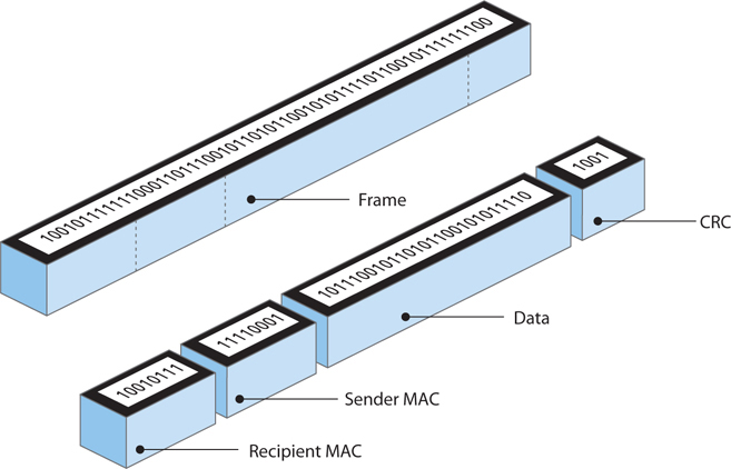
Data is moved from one device to another in discrete chunks called frames. NICs create and process frames.
NOTE You’ll sometimes hear the word packet used instead of frames—this is incorrect. Packets are a part of the frame. You’ll find more information about packets in Chapter 21, “Local Area Networking.”
Every NIC in the world has a built-in identifier, an address unique to that network card, called a media access control (MAC) address. A MAC address is a binary number, meaning it’s a string of 1s and 0s. Each 1 or 0 is called a bit.
The MAC address is 48 bits long, providing more than 281 trillion MAC addresses, so there are plenty of MAC addresses to go around. Because people have trouble keeping track of that many 1s and 0s, we need another way to display the addresses. Hexadecimal is shorthand for representing strings of 1s and 0s. One hex character is used to represent four binary characters. Here’s the key:
0000 = 0
0001 = 1
0010 = 2
0011 = 3
0100 = 4
0101 = 5
0110 = 6
0111 = 7
1000 = 8
1001 = 9
1010 = A
1011 = B
1100 = C
1101 = D
1110 = E
1111 = F
So, MAC addresses may be binary, but we represent them by using 12 hexadecimal characters. These MAC addresses are burned into every NIC, and some NIC makers print the MAC address on the card. Figure 20-6 shows the System Information utility description of a NIC, with the MAC address highlighted.
Figure 20-6 MAC address
NOTE Even though MAC addresses are embedded into the NIC, some NICs allow you to change the MAC address on the NIC. This is rarely done.
Hey! I thought we were talking about frames! Well, we are, but you needed to understand MAC addresses to understand frames.
The many varieties of frames share common features (see Figure 20-7). First, frames contain the MAC address of the network card to which the data is being sent. Second, they have the MAC address of the network card that sent the data. Third is the data itself (at this point, we have no idea what the data is—certain software handles that question), which can vary in size depending on the type of frame. Finally, the frame must contain some type of data check to verify that the data was received in good order. Most frames use a clever mathematical algorithm called a cyclic redundancy check (CRC).
Figure 20-7 Generic frame
MAC Address Search
Every personal computing device has a MAC address assigned to each network connection type it offers. Any number of troubleshooting scenarios will have you scrambling to find a device’s MAC address, so try this!
You have many ways to discover the MAC address(es) in Windows, Mac OS X, and Linux. The simplest is through the command-line interface. Here’s a method in Windows. At the prompt, type ipconfig /all and press ENTER. You’ll find the MAC address listed as the “Physical Address” under the Ethernet adapter Local Area Connection category.
Which command do you think would work at the Terminal in Mac OS X and Linux? How do you figure out which switch to use? (Refresh your memory of commands in Chapter 16, “Working with the Command-Line Interface.”)
This discussion of frames raises a question: How big is a frame? Or more specifically, how much data do you put into each frame? How do you ensure that the receiving system understands the way the data was broken down by the sending machine and can thus put the pieces back together? The hard part of answering these questions is that they encompass so many items. When the first networks were created, everything from the frames to the connectors to the type of cable had to be invented from scratch.
To make a successful network, you need the sending and receiving devices to use the same network technology. Over the years, many hardware protocols came and went, but today only one hardware protocol dominates the modern computing landscape: Ethernet. Ethernet was developed for wired networking, but even wireless networks use Ethernet as the basis for their signals. If you want to understanding networking, you need to understand Ethernet.
A consortium of companies centered on Digital Equipment Corporation, Intel, and Xerox invented the first network in the mid-1970s. More than just create a network, they wrote a series of standards that defined everything necessary to get data from one computer to another. This series of standards was called Ethernet. Over the years, Ethernet has gone through hundreds of distinct improvements in areas such as speed, signaling, and cabling. We call these improvements Ethernet flavors.
Through all the improvements in Ethernet, the Ethernet frame hasn’t changed in over 25 years. This is very important: you can have any combination of hardware devices and cabling using different Ethernet flavors on a single Ethernet network and, in most cases, the hosts will be able to communicate just fine.
Most modern Ethernet networks employ one of three speeds: 10BaseT, 100BaseT, or 1000BaseT. As the numbers in the names suggest, 10BaseT networks run at 10 Mbps, 100BaseT networks run at 100 Mbps, and 1000BaseT networks—called Gigabit Ethernet—run at 1000 Mbps, or 1 Gbps. All three technologies—sometimes referred to collectively as 10/100/1000BaseT or just plain Ethernet—use a star bus topology and connect via a type of cable called unshielded twisted pair (UTP).
NOTE Ethernet developers continue to refine the technology. 1000BaseT might be the most common desktop standard now, but 10-Gigabit Ethernet is common on server-to-server connections. 40/100-Gigabit Ethernet is slowly encroaching as well.
With all Ethernet networks (with the exception of some very old flavors), every individual host connects to a central box. You attach each system to this box via cables to special ports. The box takes care of all of the tedious details required by the network to get frames sent to the correct systems. This layout, which looks something like a star, is called a star bus topology (see Figure 20-8). (The bus refers to the internal wiring in the box. The star refers to the wires leading from the box to the hosts.)
Figure 20-8 Ethernet star bus
The central box—the switch—provides a common point of connection for network devices. Switches can have a wide variety of ports. Most consumer-level switches have 4 or 8 ports, but business-level switches can have 32 or more ports.
Early Ethernet networks used a hub. A switch is a far superior and far more common version of a hub. Figure 20-9 shows a typical consumer-level switch.
Figure 20-9 A switch
Hubs and switches look pretty much identical and they perform the same basic job: taking the signal from one host and then repeating the signal out to other hosts. Even though they look the same and do functionally the same job, they do the job differently. Basically, hubs are stupid repeaters: anything sent in one port automatically goes out all the other connected ports. Switches are smart repeaters: they memorize the MAC addresses of all the connected devices and only send out repeated signals to the correct host. This makes switched networks much faster than hubbed networks.
A simple example demonstrates the difference between hubs and switches. Let’s say you have a network of 32 machines, all using 100-Mbps NICs attached to a 100-Mbps hub or switch. We would say the network’s bandwidth is 100 Mbps. If you put the 32 systems on a 32-port 100-Mbps hub, you have 32 computers sharing the 100 Mbps of bandwidth. A switch addresses this problem by making each port its own separate network. Each system gets to use the full bandwidth. The bottom line? Once switches became affordable, hubs went away.
The connection between a computer and a switch is called a segment. With most cable types, Ethernet segments are limited to 100 meters or less. You cannot use a splitter to split a single segment into two or more connections with an Ethernet network that uses this star bus topology. Doing so prevents the switch from recognizing which host is sending or receiving a signal and no hosts connected to a split segment will be able to communicate. Splitters negatively effect signal quality.
Cheap and centralized, Ethernet’s star bus topology does not go down if a single cable breaks. True, the network would go down if the switch failed, but that is rare.
Unshielded twisted pair (UTP) cabling is the specified cabling for 10/100/1000BaseT and is the predominant cabling system used today. Many types of twisted pair cabling are available, and the type used depends on the needs of the network. Twisted pair cabling consists of AWG 22–26 gauge wire twisted together into color-coded pairs. Each wire is individually insulated and encased as a group in a common jacket.
CAT Levels UTP cables come in categories that define the maximum speed at which data can be transferred (also called bandwidth). The major categories (CATs) are outlined in Table 20-1.
Table 20-1 CAT Levels
The CAT level should be clearly marked on the cable, as Figure 20-10 shows.
Figure 20-10 Cable markings for CAT level

EXAM TIP Although these days you’ll only find CAT 3 installed for telephones and in very old network installations, CompTIA traditionally enjoys tripping up techs who don’t know it could handle 100-Mbps networks.
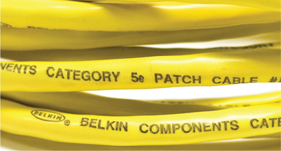
The Telecommunication Industry Association/Electronics Industries Alliance (TIA/EIA) establishes the UTP categories, which fall under the TIA/EIA 568 specification. Currently, most installers use CAT 5e, CAT 6, or CAT 6a cable.
Shielded twisted pair (STP), as its name implies, consists of twisted pairs of wires surrounded by shielding to protect them from EMI, or electromagnetic interference. STP is pretty rare, primarily because there’s so little need for STP’s shielding; it only really matters in locations with excessive electronic noise, such as a shop floor area with lots of lights, electric motors, or other machinery that could cause problems for other cables.
The 10BaseT and 100BaseT standards require two pairs of wires: a pair for sending and a pair for receiving. 10BaseT ran on an ancient CAT version called CAT 3, but typically used at least CAT 5 cable. 100BaseT requires at least CAT 5 to run. 1000BaseT needs all four pairs of wires in CAT 5e and higher cables. These cables use a connector called an RJ-45 connector. The RJ (registered jack) designation was invented by Ma Bell (the phone company, for you youngsters) years ago and is still used today.
NOTE There are CAT levels for connectors as well as cables. Don’t even try to use a CAT 5e RJ-45 connector with a CAT 6 cable.
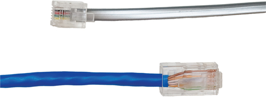
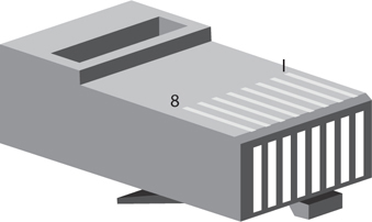
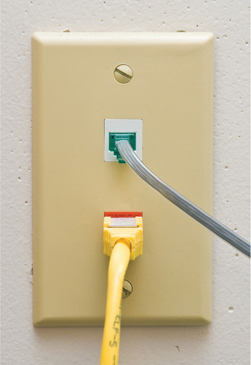
Currently only two types of RJ connectors are used for networking: RJ-11 and RJ-45 (see Figure 20-11). RJ-11 connects your telephone to the telephone jack in the wall of your house. It supports up to two pairs of wires, though most phone lines use only one pair. The other pair is used to support a second phone line. RJ-11 connectors are primarily used for telephone-based Internet connections (see Chapter 23, “The Internet”). RJ-45 is the standard for UTP connectors. RJ-45 has connections for up to four pairs and is visibly much wider than RJ-11. Figure 20-12 shows the position of the #1 and #8 pins on an RJ-45 jack.
Figure 20-11 RJ-11 and RJ-45
Figure 20-12 RJ-45 pin numbers
The TIA/EIA has two standards for connecting the RJ-45 connector to the UTP cable: the TIA/EIA 568A (T568A) and the TIA/EIA 568B (T568B). Both are acceptable. You do not have to follow any standard as long as you use the same pairings on each end of the cable; however, you will make your life simpler if you choose a standard. Make sure that all of your cabling uses the same standard and you will save a great deal of work in the end. Most importantly, keep records!
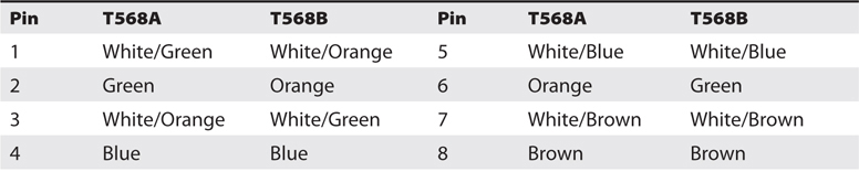
Like all wires, the wires in UTP are numbered. A number does not appear on each wire, but rather each wire has a standardized color. Table 20-2 shows the official TIA/EIA Standard Color Chart for UTP.
Table 20-2 UTP Cabling Color Chart
SIMS Check out the “568B” simulation at the Total Seminars Training Hub for practice on a simulation you might see on the CompTIA A+ 901 exam: http://hub.totalsem.com. You’ll find it in TotalSims for A+, Chapter 20.
Most workplace installations of network cable go up above the ceiling and then drop down through the walls to present a nice port in the wall. The space in the ceiling, under the floors, and in the walls through which cable runs is called the plenum space. The potential problem with this cabling running through the plenum space is that the protective sheathing for networking cables, called the jacket, is made from plastic, and if you get any plastic hot enough, it creates smoke and noxious fumes.
Standard network cables usually use PVC (polyvinyl chloride) for the jacket, but PVC produces noxious fumes when burned. Fumes from cables burning in the plenum space can quickly spread throughout the building, so you want to use a more fire-retardant cable in the plenum space. Plenum-grade cable is simply network cabling with a fire-retardant jacket required for cables that go in the plenum space. Plenum-grade cable costs about three to five times more than PVC, but you should use it whenever you install cable in a plenum space.
You can hook two computers directly together using a special UTP cable called a crossover cable. A crossover cable is a standard UTP cable with one RJ-45 connector using the T568A standard and the other using the T568B standard. This reverses the signal between sending and receiving wires and thus does the job of a hub or switch. Crossover cables work great as a quick way to connect two computers directly for a quick and dirty network. You can purchase a crossover cable at any computer store.
UTP is very popular, but Ethernet, as well as other types of networks, can use alternative cabling that you need to be able to identify. Every CompTIA A+ certified tech needs to know about fiber optic cable and coaxial cable, so let’s start there.
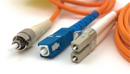
Fiber optic cable is a very attractive way to transmit Ethernet network frames. First, because it uses light instead of electricity, fiber optic cable is immune to electrical problems such as lightning, short circuits, and static. Second, fiber optic signals travel much farther, 2000 meters or more (compared with 100 meters on UTP). Most fiber Ethernet networks use 62.5/125 multimode fiber optic cable. All fiber Ethernet networks that use this type of cabling require two cables. Figure 20-13 shows three of the more common connectors used in fiber optic networks. The round connector on the left is called an ST connector. The square-shaped middle connecter is called an SC connector, and on the far right is an LC connector.
Figure 20-13 Typical fiber optic cables with ST, SC, and LC connectors
Fiber optics are half-duplex, meaning data flows only one way—hence the need for two cables in a fiber installation. With the older ST and SC connectors, you needed two connectors on every fiber connection. Newer connectors like LC are designed to support two fiber cables in one connecter, a real space saver.
Multimode and Single-Mode Light can be sent down a fiber optic cable as regular light or as laser light. Each type of light requires totally different fiber optic cables. Most network technologies that use fiber optics use light-emitting diodes (LEDs) to send light signals. These use multimode fiber optic cabling. Multimode fiber transmits multiple light signals at the same time, each using a different reflection angle within the core of the cable. The multiple reflection angles tend to disperse over long distances, so multimode fiber optic cables are used for relatively short distances.
EXAM TIP Know fiber connector types and the difference between multimode and single-mode fiber.
Network technologies that use laser light use single-mode fiber optic cabling. Using laser light and single-mode fiber optic cables allows for phenomenally high transfer rates over long distances. Except for long-distance links, single-mode is currently quite rare; if you see fiber optic cabling, you can be relatively sure it is multimode.
There are close to 100 different Ethernet fiber optic cabling standards, with names like 1000BaseSX and 10GBaseSR. The major difference is the speed of the network (there are also some important differences in the way systems interconnect, and so on). If you want to use fiber optic cabling, you need a fiber optic switch and fiber optic network cards.
Fiber networks follow the speed and distance limitations of their networking standard, so it’s hard to pin down precise numbers on true limitations. Multimode overall is slower and has a shorter range than single-mode. A typical multimode network runs at 10, 100, or 1000 Mbps, though some can go to 10,000 Mbps. Distances for multimode runs generally top out at ~600 meters. With single-mode, speed and distance—depending on the standard—can blow multimode away. The record transmission speed way back in 2011, for example, was 100 terabits per second, and that was over 100 miles!
EXAM TIP There are a number of Ethernet standards that use fiber optic cable instead of UTP.
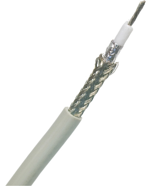
Early versions of Ethernet ran on coaxial cable instead of UTP. While the Ethernet standards using coax are long gone, coax lives on in the networking world, primarily for cable modems and satellite connections. Coax cable consists of a center cable (core) surrounded by insulation. This in turn is covered with a shield of braided cable (see Figure 20-14). The center core actually carries the signal. The shield effectively eliminates outside interference. The entire cable is then surrounded by a protective insulating cover.
Figure 20-14 Typical coax
Coax cables are rated using an RG name. There are hundreds of RG ratings for coax, but the only two you need to know for the CompTIA A+ exam are RG-59 and RG-6. Both standards are rated by impedance, which is measured in ohms. (Impedance is the effective resistance to the flow of an alternating current electrical signal through a cable.) Both RG-6 and RG-59 have a 75-ohm impedance. Both of these coax cables are used by your cable television, but RG-59 is thinner and doesn’t carry data quite as far as RG-6. The RG rating is clearly marked on the cable.
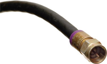
Coax most commonly uses two different types of connectors. A BNC (Bayonet Neill-Concelman or British Naval) connector (see Figure 20-15) uses a quarter twist connector, and an F-type connector uses a screw connector. BNC is uncommon, but F-type is on the back of all cable modems and most televisions (see Figure 20-16).
Figure 20-15 BNC connector
Figure 20-16 F-type connector
EXAM TIP Coaxial cable implementations offer amazing speeds, topping 100 Mbps in some cases. Using splitters negatively effects signal quality, lowering speeds.
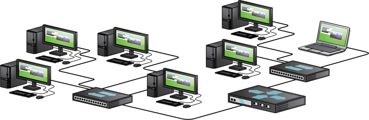
Regardless of the cabling choice—UTP or fiber—Ethernet networks roll out into a star bus topology. The illustration of a star used earlier in the chapter doesn’t quite translate into real life, so let’s turn briefly to look at common implementations of Ethernet.
A local area network (LAN) is a group of computers located physically close to each other—no more than a few hundred meters apart at most. A LAN might be in a single room, on a single floor, or in a single building. But I’m going to add that a LAN is almost always a group of computers that are able to “hear” each other when one of them sends a broadcast. A group of computers connected by one or more switches is a broadcast domain (see Figure 20-17), which means that all nodes receive broadcast frames from every other node.
Figure 20-17 Two broadcast domains—two separate LANs
EXAM TIP For the CompTIA A+ exams, remember that a LAN is a group of networked computers that are close to each other. Also, remember that a LAN is almost always a broadcast domain.
You can set up a LAN in a small office/home office (SOHO) environment in several ways. The most common way—using wireless technology called Wi-Fi—dispenses with wires altogether. We’ll get there in detail in Chapter 22, “Wireless Networking.”
Another option uses the existing electrical network in the building for connectivity. This option, called Ethernet over Power, requires specialized bridges that connect to power outlets. Figure 20-18 shows a typical Ethernet over Power bridge.
Figure 20-18 Ethernet over Power Bridge
A bridge is a device that connects dissimilar network technologies that transmit the same signal. In this case the bridge connects UTP to power lines. There are many other places we see bridges: there are bridge devices to connect wireless to UTP, coax to UTP, and so forth.
Ethernet over Power has its place in the right situations, but there are many challenges. First, several incompatible standards compete in the marketplace, which usually means you need to buy from the same manufacturer. Second, the fastest versions run at 100 Mbps at best, which may not be enough bandwidth for heavy use. But if you have a computer in a weird place where wireless won’t work and traditional cables can’t reach, try Ethernet over Power.
If you want a functioning, dependable, real-world network, you need a solid understanding of a set of standards collectively called structured cabling. These standards, defined by the TIA/EIA—yes, the same folks who tell you how to crimp an RJ-45 onto the end of a UTP cable—give professional cable installers detailed standards on every aspect of a cabled network, from the type of cabling to use to standards on running cable in walls, even the position of wall outlets.
The CompTIA A+ exams require you to understand the basic concepts involved in installing network cabling and to recognize the components used in a network. The CompTIA A+ exams do not, however, expect you to be as knowledgeable as a professional network designer or cable installer. Your goal should be to understand enough about real-world cabling systems to communicate knowledgeably with cable installers and to perform basic troubleshooting. Granted, by the end of this section, you’ll know enough to try running your own cable (I certainly run my own cable), but consider that knowledge extra credit.
The idea of structured cabling is to create a safe, reliable cabling infrastructure for all of the devices that may need interconnection. Certainly this applies to computer networks, but also to telephone, video—anything that might need low-power, distributed cabling.
NOTE A structured cabling system is useful for more than just computer networks. You’ll find structured cabling defining telephone networks and video conferencing setups, for example.
You should understand three issues with structured cabling. We’ll start with the basics of how cables connect switches and computers. You’ll then look at the components of a network, such as how the cable runs through the walls and where it ends up. This section wraps up with an assessment of connections leading outside your network.
Earlier in this chapter we developed the idea of an Ethernet LAN in its most basic configuration: a switch, some UTP cable, and a few computers—in other words, a typical physical star network (see Figure 20-19).
Figure 20-19 A switch connected by UTP cable to two computers
No law of physics prevents you from placing a switch in the middle of your office and running cables on the floor to all the computers in your network. This setup works, but it falls apart spectacularly when applied to a real-world environment. Three problems present themselves to the network tech. First, the exposed cables running along the floor are just waiting for someone to trip over them, giving that person a wonderful lawsuit opportunity. Simply moving and stepping on the cabling will, over time, cause a cable to fail due to wires breaking or RJ-45 connectors ripping off cable ends. Second, the presence of other electrical devices close to the cable can create interference that confuses the signals going through the wire. Third, this type of setup limits your ability to make any changes to the network. Before you can change anything, you have to figure out which cables in the huge rat’s nest of cables connected to the switch go to which machines. Imagine that troubleshooting nightmare!
“Gosh,” you’re thinking (okay, I’m thinking it, but you should be, too), “there must be a better way to install a physical network.” A better installation would provide safety, protecting the star from vacuum cleaners, clumsy coworkers, and electrical interference. It would have extra hardware to organize and protect the cabling. Finally, the new and improved star network installation would feature a cabling standard with the flexibility to enable the network to grow according to its needs and then to upgrade when the next great network technology comes along. That is the definition of structured cabling.
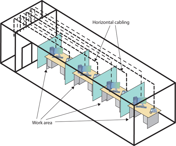
Successful implementation of a basic structured cabling network requires three essential ingredients: a telecommunications room, horizontal cabling, and a work area. Let’s zero in on one floor of a typical office. All the cabling runs from individual workstations to a central location, the telecommunications room (see Figure 20-20). What equipment goes in there—a switch or a telephone system—is not the important thing. What matters is that all the cables concentrate in this one area.
Figure 20-20 Telecommunications room
All cables run horizontally (for the most part) from the telecommunications room to the workstations. This cabling is called, appropriately, horizontal cabling. A single piece of installed horizontal cabling is called a run. At the opposite end of the horizontal cabling from the telecommunications room is the work area. The work area is often simply an office or cubicle that potentially contains a workstation and a telephone. Figure 20-21 shows both the horizontal cabling and work areas.
Figure 20-21 Horizontal cabling and work areas
Each of the three parts of a basic star network—the telecommunications room, the horizontal cabling, and the work area(s)—must follow a series of strict standards designed to ensure that the cabling system is reliable and easy to manage. The cabling standards set by TIA/EIA enable techs to make sensible decisions on equipment installed in the telecommunications room, so let’s tackle horizontal cabling first, and then return to the telecommunications room. We’ll finish up with the work area.
Horizontal Cabling A horizontal cabling run is the cabling that goes more or less horizontally from a work area to the telecommunications room. In most networks, this cable is a CAT 5e or better UTP, but when you move into structured cabling, the TIA/EIA standards define a number of other aspects of the cable, such as the type of wires, number of pairs of wires, and fire ratings.
EXAM TIP A single piece of cable that runs from a work area to a telecommunications room is called a run. In most networks, this cable is CAT 5e or better UTP.
Solid Core Versus Stranded Core All UTP cables come in one of two types: solid core or stranded core. Each wire in solid core UTP uses a single solid wire. With stranded core, each wire is actually a bundle of tiny wire strands. Each of these cable types has its benefits and downsides. Solid core is a better conductor, but it is stiff and will break if handled too often or too roughly. Stranded core is not quite as good a conductor, but it will stand up to substantial handling without breaking. Figure 20-22 shows a close-up of solid and stranded core UTP.
Figure 20-22 Solid and stranded core UTP
TIA/EIA specifies that horizontal cabling should always be solid core. Remember, this cabling is going into your walls and ceilings, safe from the harmful effects of shoes and vacuum cleaners. The ceilings and walls enable you to take advantage of the better conductivity of solid core without the risk of cable damage. Stranded cable also has an important function in a structured cabling network, but I need to discuss a few more parts of the network before I talk about where to use stranded UTP cable.
The telecommunications room is the heart of the basic star. This room is where all the horizontal runs from all the work areas come together. The concentration of all this gear in one place makes the telecommunications room potentially one of the messiest parts of the basic star. Even if you do a nice, neat job of organizing the cables when they are first installed, networks change over time. People move computers, new work areas are added, network topologies are added or improved, and so on. Unless you impose some type of organization, this conglomeration of equipment and cables decays into a nightmarish mess.
Fortunately, the TIA/EIA structured cabling standards define the use of specialized components in the telecommunications room that make organizing a snap. In fact, it might be fair to say that there are too many options! To keep it simple, we’re going to stay with the most common telecommunications room setup and then take a short peek at some other fairly common options.
Equipment Racks The central component of every telecommunications room is one or more equipment racks. An equipment rack provides a safe, stable platform for all the different hardware components. All equipment racks are 19 inches wide, but they vary in height from two- to three-foot-high models that bolt onto a wall (see Figure 20-23) to the more popular floor-to-ceiling models (see Figure 20-24).
Figure 20-23 A short equipment rack
Figure 20-24 A floor-to-ceiling rack
NOTE Equipment racks evolved out of the railroad signaling racks from the 19th century. The components in a rack today obviously differ a lot from railroad signaling, but the 19-inch width has remained the standard for well over 100 years.
You can mount almost any network hardware component into a rack. All manufacturers make rack-mounted switches that mount into a rack with a few screws. These switches are available with a wide assortment of ports and capabilities. There are even rack-mounted servers, complete with slide-out keyboards, and rack-mounted uninterruptible power supplies (UPSs) to power the equipment (see Figure 20-25).
Figure 20-25 A rack-mounted UPS
All rack-mounted equipment uses a height measurement known simply as a U. A U is 1.75 inches. A device that fits in a 1.75-inch space is called a 1U; a device designed for a 3.5-inch space is a 2U; and a device that goes into a 7-inch space is called a 4U. Most rack-mounted devices are 1U, 2U, or 4U.
Patch Panels and Cables Ideally, once you install horizontal cabling, you should never move it. As you know, UTP horizontal cabling has a solid core, making it pretty stiff. Solid core cables can handle some rearranging, but if you insert a wad of solid core cables directly into your switches, every time you move a cable to a different port on the switch, or move the switch itself, you will jostle the cable. You don’t have to move a solid core cable many times before one of the solid copper wires breaks, and there goes a network connection!
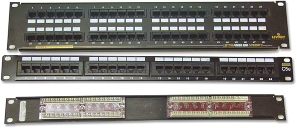
Luckily for you, you can easily avoid this problem by using a patch panel. A patch panel is simply a box with a row of female connectors (ports) in the front and permanent connections in the back, to which you connect the horizontal cables (see Figure 20-26).
Figure 20-26 Typical patch panels
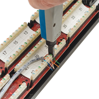
The most common type of patch panel today uses a special type of connecter called a 110 block, or sometimes a 110-punchdown block. UTP cables connect to a 110 block using a punchdown tool. Figure 20-27 shows a typical punchdown tool, and Figure 20-28 shows the punchdown tool punching down individual strands.
Figure 20-27 Punchdown tool
Figure 20-28 Punching down a 110 block
The punchdown block has small metal-lined grooves for the individual wires. The punchdown tool has a blunt end that forces the wire into the groove. The metal in the groove slices the cladding enough to make contact.
EXAM TIP The CompTIA A+ exams expect you to know that a punchdown tool is used for securing UTP connections to a punchdown block. It’s not until you go for CompTIA Network+ certification that you’ll be expected to know how to use these tools.
Not only do patch panels prevent the horizontal cabling from being moved, but they are also your first line of defense in organizing the cables. All patch panels have space in the front for labels, and these labels are the network tech’s best friend! Simply place a tiny label on the patch panel to identify each cable, and you will never have to experience that sinking feeling of standing in the telecommunications room of your nonfunctioning network, wondering which cable is which. If you want to be a purist, there is an official, and rather confusing, TIA/EIA labeling methodology called TIA/EIA 606, but a number of real-world network techs simply use their own internal codes (see Figure 20-29).
Figure 20-29 Typical patch panels with labels
Patch panels are available in a wide variety of configurations that include different types of ports and numbers of ports. You can get UTP, STP, or fiber ports, and some manufacturers combine several different types on the same patch panel. Panels are available with 8, 12, 24, 48, or even more ports.
UTP patch panels, like UTP cables, come with CAT ratings, which you should be sure to check. Don’t blow a good CAT 6 cable installation by buying a cheap patch panel—get a CAT 6 patch panel! A higher-rated panel supports earlier standards, so you can use a CAT 6 or even CAT 6a rack with CAT 5e cabling. Most manufacturers proudly display the CAT level right on the patch panel (see Figure 20-30).
Figure 20-30 CAT level on patch panel
Once you have installed the patch panel, you need to connect the ports to the switch through patch cables. Patch cables are short (typically two- to five-foot) UTP cables. Patch cables use stranded rather than solid cable, so they can tolerate much more handling. Even though you can make your own patch cables, most people buy premade ones. Buying patch cables enables you to use different-colored cables to facilitate organization (yellow for accounting, blue for sales, or whatever scheme works for you). Most prefabricated patch cables also come with a reinforced (booted) connector specially designed to handle multiple insertions and removals (see Figure 20-31).
Figure 20-31 Typical patch cable
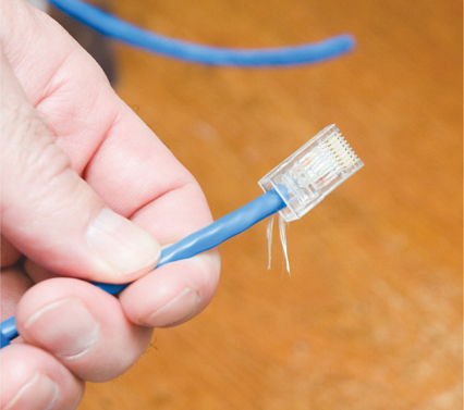
Rolling Your Own Patch Cables Although most people prefer simply to purchase premade patch cables, making your own is fairly easy. To make your own, use stranded UTP cable that matches the CAT level of your horizontal cabling. Stranded cable also requires specific crimps, so don’t use crimps designed for solid cable. Crimping is simple enough, although getting it right takes some practice.
Figure 20-32 shows the two main tools of the crimping trade: an RJ-45 crimper with built-in wire stripper and a pair of wire snips. Professional cable installers naturally have a wide variety of other tools as well.
Figure 20-32 Crimper and snips
EXAM TIP The CompTIA A+ exams expect you to know that a cable tech uses a crimper or crimping tool to attach an RJ-45 to the end of a UTP cable.
Here are the steps for properly crimping an RJ-45 onto a UTP cable. If you have some crimps, cable, and a crimping tool handy, follow along!
1. Cut the cable square using RJ-45 crimpers or scissors.
2. Strip off one-half inch of plastic jacket from the end of the cable (see Figure 20-33).
Figure 20-33 Properly stripped cable
3. Slowly and carefully insert each individual wire into the correct location according to either TIA/EIA 568A or B (see Figure 20-34). Unravel as little as possible.
Figure 20-34 Inserting the individual strands
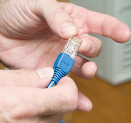
4. Insert the crimp into the crimper and press (see Figure 20-35). Don’t worry about pressing too hard; the crimper has a stop to prevent you from using too much pressure.
Figure 20-35 Crimping the cable
Figure 20-36 shows a nicely crimped cable. Note how the plastic jacket goes into the crimp.
Figure 20-36 Properly crimped cable
A good patch cable should include a boot. Figure 20-37 shows a boot being slid onto a newly crimped cable. Don’t forget to slide each boot onto the patch cable before you crimp both ends!
Figure 20-37 Adding a boot
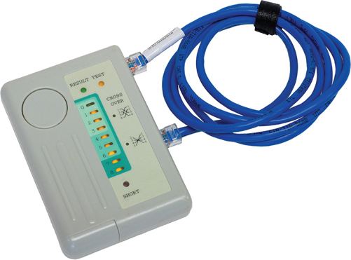
After making a cable, you need to test it to make sure it’s properly crimped. We use a handy cable tester, available in any good electronics store, to verify all the individual wires are properly connected and in the correct location (see Figure 20-38).
Figure 20-38 Typical tester
From a cabling standpoint, a work area is nothing more than a wall outlet that serves as the termination point for horizontal network cables: a convenient insertion point for a workstation and a telephone. (In practice, of course, the term “work area” includes the office or cubicle.) A wall outlet itself consists of one or two female jacks to accept the cable, a mounting bracket, and a faceplate. You connect the workstation to the wall outlet with a patch cable (see Figure 20-39).
Figure 20-39 Typical work area outlet
The female RJ-45 jacks in these wall outlets also have CAT ratings. You must buy CAT-rated jacks for wall outlets to go along with the CAT rating of the cabling in your network. In fact, many network connector manufacturers use the same connectors, often 110 punchdowns, in the wall outlets that they use on the patch panels (see Figure 20-40). These modular outlets significantly increase the ease of installation.
Figure 20-40 Punching down a modular jack
The last step is connecting the workstation to the wall outlet. Here again, most folks use a patch cable. Its stranded cabling stands up to the abuse caused by moving equipment, not to mention the occasional kick.
The work area may be the simplest part of the structured cabling system, but it is also the source of most network failures. When a user can’t access the network and you suspect a broken cable, the first place to look is the work area.
A wide area network (WAN) is a widespread group of computers connected using long-distance technologies. You connect LANs into a WAN with a magical box called a router (see Figure 20-41). The best example of a WAN is the Internet.
Figure 20-41 Two broadcast domains connected by a router—a WAN
You can connect multiple smaller networks into a bigger network, turning a group of LANs into one big WAN, but this raises a couple of issues with network traffic. A computer needs some form of powerful, flexible addressing to address a frame so that it goes to a computer within its own LAN or to a computer on another LAN on the same WAN. Broadcasting is also unacceptable, at least between LANs. If every computer saw every frame, the network traffic would quickly spin out of control! Plus, the addressing scheme needs to work so that routers can sort the frames and send them along to the proper LAN. This process, called routing, requires routers and a routing-capable protocol to function correctly.
Routers destroy any incoming broadcast frames, by design. No broadcast frame can ever go through a router. This makes broadcasting still quite common within a single broadcast domain, but never anywhere else.
To go beyond a LAN requires a network protocol—a way machines agree to communicate—that can handle routing. That protocol, for the vast majority of networks, is called TCP/IP, and Chapter 21 begins with the details. For now, review the end-of-chapter material and take some practice exams. See you in Chapter 21!
1. How many bits are in a MAC address?
A. 24
B. 36
C. 48
D. 64
2. What is the minimum CAT level cable required for a 100BaseT network?
A. CAT 1
B. CAT 5
C. CAT 5e
D. CAT 6
3. Which of the following is an example of a hybrid topology?
A. Bus
B. Ring
C. Star
D. Star bus
4. A typical CAT 6 cable uses which connector?
A. RJ-11
B. RJ-45
C. Plenum
D. PVC
5. Why would you use STP over UTP cabling?
A. Cheaper.
B. Easier to install.
C. Better to avoid interference.
D. They’re interchangeable terms.
6. What kind of frame gets received by all NICs in a LAN?
A. CAT 7
B. Broadcast
C. WAN
D. SC, ST, or LC
7. Microsoft Internet Explorer, Mozilla Firefox, Google Chrome, and Microsoft Edge are all examples of what?
A. Web servers
B. Print servers
C. Web browsers
D. Proxy servers
8. John’s boss asks for a recommendation for connecting the company network to a small satellite building about 1 km from the main campus. The company owns the verdant land in between. Given such a scenario, what network technology implementation should John suggest?
A. Ethernet over UTP
B. Ethernet over STP
C. Ethernet over multimode fiber
D. Ethernet over single-mode fiber
9. Erin is stuck. She needs data from a friend’s laptop to work on her desktop, but neither of them brought a thumb drive. She has any number of Ethernet cables at her disposal, but the last port on the switch is taken. What’s her best option, given such a scenario?
A. Connect the two computers directly using a patch cable.
B. Connect the two computers directly using a crossover cable.
C. Connect the two computers directly using an STP cable.
D. Run to the store, buy a thumb drive, get back to the lab, and physically move the data.
10. Eddard hands Will a cable. Will hands it back and says, meaningfully, “That’s a nice F connector you’ve got there.” What kind of cable does Eddard have?
A. Coaxial
B. Fiber optic
C. STP
D. UTP
1. C. MAC addresses are 48-bit.
2. B. 100BaseT networks need CAT 5 or better UTP.
3. D. A star bus topology, like the one used with Ethernet networks, is a hybrid topology.
4. B. CAT 6 cables use an RJ-45 connector.
5. C. Shielded twisted pair cabling handles interference from other electronics much better than unshielded twisted pair.
6. B. All NICs in a LAN will receive broadcast frames.
7. C. All these programs are Web browsers.
8. D. John should suggest the only network technology implementation (listed here) that can cover those distances, Ethernet over single-mode fiber.
9. B. Erin should connect the computers directly using a crossover cable.
10. A. Eddard has a mighty fine coaxial cable in his hands.