CHAPTER 21
Local Area Networking
In this chapter, you will learn how to
• Explain the basics of TCP/IP
• Install and configure wired networks
• Troubleshoot wired networks
Networks dominate the modern computing environment. A vast percentage of businesses have PCs connected in a small local area network (LAN), and big businesses simply can’t survive without connecting their many offices into a single wide area network (WAN).
Because networks are so common today, every good tech needs to know the basics of networking technology, operating systems, implementation, and troubleshooting. Accordingly, this chapter teaches you how to build and troubleshoot a basic network.
The first part of this chapter gets down and dirty into TCP/IP and how Windows uses it in a typical network. I’ll break down the TCP/IP protocol so you can appreciate how it works.
Next, we’ll go through the process of setting up a small network from start to finish. This includes details on planning a network, installing and configuring NICs, setting up switches, configuring TCP/IP—everything you need so that Windows will enable you to share folders, printers, libraries, and so on.
The chapter closes with a popular topic: troubleshooting a network. Modern operating systems come with plenty of powerful tools to help you when the network stops functioning. I’ll show you the tools and combine that with a troubleshooting process that helps you get a network up and running again.
901/902
TCP/IP
The Ethernet hardware protocol does a fine job of moving data from one machine to another, as you learned in Chapter 20, “Networking Essentials.” But Ethernet alone isn’t enough to make a complete network; many other functions need to be handled. For example, an Ethernet frame holds a maximum of 1500 bytes. What if the data being moved is larger than 1500 bytes? Something has to chop up the data into chunks on one end of a connection and something else needs to reassemble those chunks on the other end so the data can be put to use.
Another issue arises if one of the machines on the network has its network card replaced. Up to this point, the only way to distinguish one machine from another was by the MAC address on the network card. To solve this, each machine must have a unique name, an identifier for the network, which is “above” the MAC address. Something needs to keep track of the MAC addresses on the network and the names of the machines so that frames and names can be correlated. If you replace a PC’s network card, the network will, after some special queries, update the list to associate the name of the PC with the new network card’s MAC address.
Network protocol software takes the incoming data received by the network card, keeps it organized, sends it to the application that needs it, and then takes outgoing data from the application and hands it to the NIC to be sent out over the network. All networks use some network protocol. Over the years there have been many network protocols, most combining multiple simple protocols into groups, called protocol stacks. This lead to some crazily named network protocols, such as TCP/IP.
The Transmission Control Protocol/Internet Protocol (TCP/IP) is the primary protocol of most modern networks, including the Internet. For a computing device to access the Internet, it must have TCP/IP loaded and configured properly. Let’s look at some aspects of the TCP/IP protocol suite.
Network Addressing with IPv4
Any network address must provide two pieces of information: it must uniquely identify the machine and it must locate that machine within the larger network. In a TCP/IP network, the IP address identifies the node and the network on which it resides. If you look at an IP address, it’s not apparent which part of the address identifies the network and which part is the unique identifier of the computer.
IP Addresses
The IP address is the unique identification number for your system on the network. Most systems today rely on the Internet Protocol version 4 (IPv4) addressing scheme. IPv4 addresses consist of four sets of eight binary numbers (octets), each set separated by a period. This is called dotted-decimal notation. So, instead of a computer being called SERVER1, it gets an address like so:
202.34.16.11
Written in binary form, the address would look like this:
11001010.00100010.00010000.00001011
To make the addresses more comprehensible to users, the TCP/IP folks decided to write the decimal equivalents:
00000000 = 0
00000001 = 1
00000010 = 2
…
11111111 = 255
Subnet Mask
Part of every IP address identifies the network (the network ID), and another part identifies the local computer (the host ID, or host) on the network. A NIC uses a value called the subnet mask to distinguish which part of the IP address identifies the network ID and which part of the address identifies the host. The subnet mask blocks out (or masks) the network portion of an IP address.
Let’s look at a typical subnet mask: 255.255.255.0. When you compare the subnet mask to the IP address, any part that’s all 255s is the network ID. Any part that’s all zeros is the host ID. Look at the following example:
IP address: 192.168.4.33
Subnet mask: 255.255.255.0
Because the first thee octets are 255, the network ID is 192.168.4 and the host ID is 33.
Every computer on a single LAN must have the same network ID and a unique host ID. That means every computer on the preceding network must have an IP address that starts with 192.168.4. Every computer on the network must have a unique IP address. If two computers have the same IP address, they won’t be able to talk to each other, and other computers won’t know where to send data. This is called an IP conflict.
You can never have an IP address that ends with a 0 or a 255, so for the preceding example, we can have addresses starting at 192.168.4.1 and ending at 192.168.4.254: a total of 254 addresses.
Originally, subnets fell into “classes,” such as A, B, or C, determined by the corresponding octet in the subnet mask. A Class C address, like the one just discussed, had a subnet mask of 255.255.255.0. A Class B address, in contrast, had a subnet mask of 255.255.0.0. The latter class left two full octets (16 bits) just for host numbers. That meant a single Class B network ID could have 216 – 2 unique host IDs = 65,534 addresses.
Although it’s still common to see subnet masks as one to three groups of “255,” the class system is long gone. Because the subnet mask numbers are binary, you can make a subnet with any number of ones in the subnet mask.
The current system is called Classless Inter-Domain Routing (CIDR) and it works easily in binary, but a little less prettily when you show the numbers in the octets. A quick example should suffice to illustrate this point.
A subnet mask of 255.255.255.0 translates into binary as such:
11111111.11111111.11111111.00000000
With CIDR, network techs refer to the subnet mask by the number of ones it contains. The preceding subnet mask, for example, has 24 ones. Jill the tech would call this subnet a /24 (whack twenty-four). As you’ve seen already, a /24 network ID offers up to 254 host IDs.
If you want a network ID that enables more host IDs, buy one that has a subnet mask with fewer ones, like this one:
11111111.11111111.11110000.00000000
Count the ones. (There are 20.) The ones mask the network ID. That leaves 12 digits for the host IDs. Do the binary math: 212 – 2 = 4094 unique addresses in a single /20 network ID.
When you change the binary number—the string of ones—to an octet, you get the following:
255.255.240.0
It might look a little odd to a new tech, but that’s a perfectly acceptable subnet mask. The binary makes sense.
From a practical standpoint, all you have to know as a tech is how to set up a computer to accept an IP address and subnet mask combination that your network administrator tells you to use.
Interconnecting Networks with Routers
Sometimes you’ll want to talk to computers that are outside your network. In that case, you’ll need to connect to a router. A router is a device that has at least two IP addresses: one that connects to your LAN’s switch and one that connects to the “next network.” That next network could be your Internet service provider (ISP) or another router at your company—who knows (and more importantly, who cares, as long as it gets there)?
Default Gateway The port on your router that connects to your LAN is given an IP address that’s part of your network ID. In most cases, this is the first address shown in Figure 21-1.

Figure 21-1 Default gateway
The IP address of the “LAN” side of your router (the port connected to your LAN) is the address your computer uses to send data to anything outside your network ID. This is called the default gateway.
Domain Name Service (DNS) Knowing that users could not remember lots of IP addresses, early Internet pioneers came up with a way to correlate those numbers with more human-friendly designations. Special computers, called domain name service (DNS) servers, keep databases of IP addresses and their corresponding names. For example, let’s say a machine with the IP address 209.34.420.163 hosts a Web site and we want it to be known as www.totalsem.com. When we set up the Web site, we would pay for a DNS server to register the DNS name www.totalsem.com to the IP address 209.34.420.163. So instead of typing “http://209.34.420.163” to access the Web page, you can type “www.totalsem.com.” Your system will then query the DNS server to get www.totalsem.com’s IP address and use that to find the right machine. Unless you want to type in IP addresses all the time, you’ll need to use DNS servers (see Figure 21-2).

Figure 21-2 Domain name service
The Internet has regulated domain names. If you want a domain name that others can access on the Internet, you must register your domain name and pay a small yearly fee. Originally, DNS names all ended with one of the following seven domain name qualifiers, called top-level domains (TLDs):
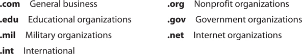
As more and more countries joined the Internet, a new level of domains was added to the original seven to indicate a DNS name from a particular country, such as .uk for the United Kingdom. It’s common to see DNS names such as www.bbc.co.uk or www.louvre.fr. The Internet Corporation for Assigned Names and Numbers (ICANN) has added many more domains, including .name, .biz, .info, .tv, and others.
Entering the IP Information When you’re configuring a computer to connect to a network, you must enter the IP address, the subnet mask, the default gateway, and at least one DNS server. Let’s review:
• IP address Your computer’s unique address on the network
• Subnet mask Identifies your network ID
• Default gateway IP address for the LAN side of your router
• DNS server Tracks easy-to-remember DNS names for IP addresses
Configuring the IP address differs between each version of Windows. Figure 21-3 shows the IP settings on a Windows 7 system.

Figure 21-3 IP settings on a Windows 7 system
As you look at Figure 21-3, note the radio button for Obtain an IP address automatically. This is a common setting for which you don’t need to enter any information. You can use this setting if your network uses Dynamic Host Control Protocol (DHCP). If you have DHCP (most networks do) and your computer is configured to obtain an IP address automatically, your computer boots up and will broadcast a DHCP request. The DHCP server provides your computer with all the IP information it needs to get on the network (see Figure 21-4).

Figure 21-4 A DHCP server handing out an IP address
You can also manually input an IP address, by the way, creating a static IP address. Static means it doesn’t change until you or some other tech changes it manually. We’ll cover static IP addresses a little later in this chapter.
TCP/UDP
When moving data from one system to another, the TCP/IP protocol suite needs to know if the communication is connection-oriented or connectionless. When you want to be positive that the data moving between two systems gets there in good order, use a connection-oriented application. If it’s not a big deal for data to miss a bit or two, then connectionless is the way to go. The connection-oriented protocol used with TCP/IP is called the Transmission Control Protocol (TCP). The connectionless one is called the User Datagram Protocol (UDP).
Let me be clear: you don’t choose TCP or UDP. The people who developed the applications decide which protocol to use. When you fire up your Web browser, for example, you’re using TCP because Web browsers use a protocol called HTTP. HTTP is built on TCP.
Over 95 percent of all TCP/IP applications use TCP. TCP gets an application’s data from one machine to another reliably and completely. As a result, TCP comes with communication rules that require both the sending and receiving machines to acknowledge the other’s presence and readiness to send and receive data.
UDP is the “fire and forget” missile of the TCP/IP protocol suite. UDP doesn’t possess any of the extras you see in TCP to make sure the data is received intact. UDP works best when you have a lot of data to send that doesn’t need to be perfect or when the systems are so close to each other that the chances of a problem occurring are too small to bother worrying about. A few dropped frames on a Voice over IP call, for example, won’t make much difference in the communication between two people. So there’s a good reason to use UDP: it’s smoking fast compared to TCP.
TCP/IP Services
TCP/IP is a different type of protocol. Although it supports File and Printer Sharing, it adds a number of unique sharing functions, lumped together under the umbrella term TCP/IP services. Most folks know the Hypertext Transfer Protocol (HTTP), the language of the World Wide Web. If you want to surf the Web, you must have TCP/IP. But TCP /IP supplies many other services beyond just HTTP. By using a service called SSH, for example, you can access a remote system’s terminal as though you were actually in front of that machine.
The goal of TCP/IP is to link any two hosts whether the two computers are on the same LAN or on some other network within the WAN. The LANs within the WAN are linked together with a variety of connections, ranging from basic dial-ups to dedicated high-speed (and expensive) data lines (see Figure 21-5). To move traffic between networks, you use routers (see Figure 21-6). Each host sends traffic to the router only when that data is destined for a remote network, cutting down on traffic across the more expensive WAN links. The host makes these decisions based on the destination IP address of each packet.
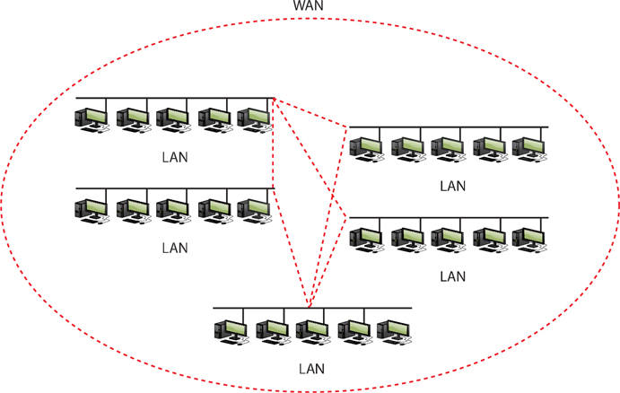
Figure 21-5 WAN concept

Figure 21-6 Typical router
TCP/IP Settings
TCP/IP has a number of unique settings that you must configure correctly to ensure proper network functionality. Unfortunately, these settings can be quite confusing, and there are several of them. Not all settings are used for every type of TCP/IP network, and it’s not always obvious where you go to set them.
In Windows, you can configure network settings from the appropriate networking applet. Right-click on Network and select Properties, or open the Control Panel and select Network and Sharing Center.
The CompTIA A+ certification exams assume that someone else, such as a tech support person or some network guru, will tell you the correct TCP/IP settings for the network. You need to understand roughly what those settings do and to know where to enter them so the system works.
TCP/IP Tools
All modern operating systems come with handy tools to test and configure TCP/IP. Those you’re most likely to use in the field are ping, ipconfig, ifconfig, nslookup, tracert, and traceroute. All of these programs are command-line utilities. Open a command prompt to run them.
ping The ping command provides a really great way to see if you can talk to another system. Here’s how it works. Get to a command prompt or terminal and type ping followed by an IP address or by a DNS name, such as ping www.chivalry.com. Press the ENTER key on your keyboard and away it goes! Figure 21-7 shows the common syntax for ping.

Figure 21-7 The ping command’s syntax
The ping command has a few useful options beyond the basics. The first option to try in Windows is the –t switch. If you use the –t switch, ping continuously sends ping packets until you stop it with the break command (CTRL-C). That’s the default behavior for ping in Mac OS X and Linux; you press the break command to make it stop. The second option in Windows is the –l switch, which enables you to specify how big a ping packet to send. This helps in diagnosing specific problems with the routers between your computer and the computer you ping.
ipconfig/ifconfig Windows offers the command-line tool ipconfig for a quick glance at your network settings. From a command prompt, type ipconfig/ all to see all of your TCP/IP settings (see Figure 21-8). The ifconfig command in Mac OS X and Linux provides the same level of detail with no switches applied.
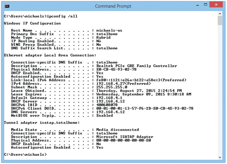
Figure 21-8 An ipconfig/ all command on Windows 8.1
When you have a static IP address, ipconfig does little beyond reporting your current IP settings, including your IP address, subnet mask, default gateway, DNS servers, and WINS servers. When using DHCP, however, ipconfig is also the primary tool for releasing and renewing your IP address. Just type ipconfig /renew to get a new IP address or ipconfig /release to give up the IP address you currently have.
nslookup The nslookup command is a powerful command-line program that enables you to determine exactly what information the DNS server is giving you about a specific host name. Every modern OS makes nslookup available when you install TCP/IP. To run the program, type nslookup from the command prompt and press the ENTER key (see Figure 21-9). Note that this gives you a little information and that the prompt has changed. That’s because you’re running the application. Type exit and press the ENTER key to return to the command prompt.

Figure 21-9 The nslookup command in action
tracert/traceroute The tracert (Windows) and traceroute (Mac OS X, Linux) utilities show the route that a packet takes to get to its destination. From a command line, type tracert or traceroute followed by a space and an IP address or URL. The output describes the route from your machine to the destination machine, including all devices the packet passes through and how long each hop between devices takes (see Figure 21-10). The tracert/traceroute command can come in handy when you have to troubleshoot bottlenecks. When users complain of difficulty reaching a particular destination by using TCP/IP, you can run this utility to determine whether the problem exists on a machine or connection over which you have control, or if it is a problem on another machine or router. Similarly, if a destination is completely unreachable, tracert/traceroute can again determine whether the problem is on a machine or router over which you have control.

Figure 21-10 The tracert command in action
Try This!
Running tracert/traceroute
Ever wonder why your e-mail takes years to get to some people but arrives instantly for others? Or why some Web sites are slower to load than others? Part of the blame could lie with how many hops away your connection is from the target server. You can use tracert/traceroute to run a quick check of how many hops it takes to get to somewhere on a network, so Try This!
1. Run tracert or traceroute on some known source, such as www.microsoft.com or www.totalsem.com. How many hops did it take? Did your tracert/traceroute time out or make it all of the way to the server?
2. Try a tracert/traceroute to a local address. If you’re in a university town, run a tracert or traceroute on the campus Web site, such as www.rice.edu for folks in Houston, or www.ucla.edu for those of you in Los Angeles. Did you get fewer hops with a local site?
Configuring TCP/IP
By default, TCP/IP is configured to receive an IP address automatically from a DHCP server on the network (and automatically assign a corresponding subnet mask). As far as the CompTIA A+ certification exams are concerned, Network+ techs and administrators give you the IP address, subnet mask, and default gateway information and you plug them into the PC. That’s about it, so here’s how to do it manually:
1. In Windows, open the Control Panel and go to the Network and Sharing Center applet. In Windows Vista, click the Manage network connections link, and in Windows 7/8/8.1/10, click Change adapter settings. After that, double-click the Local Area Network icon.
2. Click the Properties button, highlight Internet Protocol Version 4 (TCP/IPv4), and click the Properties button
3. In the Properties dialog box (see Figure 21-11), click the radio button next to Use the following IP address.

Figure 21-11 Setting up IP
4. Enter the IP address in the appropriate fields.
5. Press the TAB key to skip down to the Subnet mask field. Note that the subnet mask is entered automatically, although you can type over this if you want to enter a different subnet mask.
6. Optionally, enter the IP address for a default gateway.
7. Optionally, enter the IP addresses of a Preferred DNS server and an Alternate DNS server. (The configuration in Figure 21-11 uses the Google DNS servers.)
8. Click the OK button to close the Properties dialog box.
9. Click the Close button to exit the Local Area Connection Status dialog box.
Automatic Private IP Addressing
Modern operating systems support a feature called Automatic Private IP Addressing (APIPA) that automatically assigns an IP address to the system when the client cannot obtain an IP address automatically. The Internet Assigned Numbers Authority (IANA), the nonprofit corporation responsible for assigning IP addresses and managing root servers, has set aside the range of addresses from 169.254.0.1 to 169.254.255.254 for this purpose.
If the computer system cannot contact a DHCP server, the computer randomly chooses an address in the form of 169.254.x.y (where x.y is the computer’s identifier) and a 16-bit subnet mask (255.255.0.0) and broadcasts it on the network segment (subnet). If no other computer responds to the address, the system assigns this address to itself. When using APIPA, the system can communicate only with other computers on the same subnet that also use the 169.254.x.y range with a 16-bit mask. APIPA is enabled by default if your system is configured to obtain an IP address automatically.
Network Addressing with IPv6
When the early developers of the Internet set out to create an addressing or naming scheme for devices on the Internet, they faced several issues. Of course they needed to determine how the numbers or names worked, and for that they developed the Internet Protocol and IP addresses. But beyond that, they had to determine how many computers might exist in the future, and then make the IP address space even bigger to give Internet naming longevity. But how many computers would exist in the future?
The 32-bit IPv4 standard offers only 4 billion addresses. That was plenty in the beginning, but seemed insufficient once the Internet went global.
The Internet Engineering Task Force (IETF) developed an IP addressing scheme called Internet Protocol version 6 (IPv6) that is slowly replacing IPv4. IPv6 extends the 32-bit IP address space to 128 bits, allowing up to 2128 addresses! That should hold us for the foreseeable future! This number—close to 3.4 × 1038 addresses—is something like all the grains of sand on Earth or 1/8 of all the molecules in the atmosphere.
Although they achieve the same function—enabling computers on IP networks to send packets to each other—IPv6 and IPv4 differ a lot when it comes to implementation. This section provides you with a quick overview to get you up to speed with IPv6 and show you how it differs from IPv4.
IPv6 Address Notation
The familiar 32-bit IPv4 addresses are written as 197.169.94.82, using four octets. The 128-bit IPv6 addresses are written like this:
2001:0000:0000:3210:0800:200C:00CF:1234
IPv6 uses a colon as a separator, instead of the period used in IPv4’s dotted-decimal format. Each “group” is a hexadecimal number between 0000 and FFFF called, unofficially, a field or hextet.
A complete IPv6 address always has eight groups of four hexadecimal characters. If this sounds like you’re going to type in really long IP addresses, don’t worry, IPv6 offers a number of ways to shorten the address in written form.
First, leading zeros can be dropped from any group, so 00CF becomes CF and 0000 becomes 0. Let’s rewrite the previous IPv6 address using this shortening method:
2001:0:0:3210:800:200C:CF:1234
Second, you can remove one or more consecutive groups of all zeros, leaving the two colons together. For example, using the :: rule, you can write the IPv6 address
2001:0:0:3210:800:200C:CF:1234
as
2001::3210:800:200C:CF:1234
You can remove any number of consecutive groups of zeros to leave a double colon, but you can only use this trick once in an IPv6 address.
Take a look at this IPv6 address:
FEDC:0000:0000:0000:00CF:0000:BA98:1234
Using the double-colon rule, you can reduce four groups of zeros; three of them follow the FEDC and the fourth comes after 00CF. Because of the “only use once” stipulation, the best and shortest option is to convert the address to
FEDC::CF:0:BA98:1234
You may not use a second :: to represent the fourth groups of zeros—only one :: is allowed per address! This rule exists for a good reason. If more than one :: was used, how could you tell how many groups of zeros were in each group? Answer: you couldn’t.
Here’s an example of a very special IPv6 address that takes full advantage of the double-colon rule, the IPv6 loopback address:
::1
Without using the double-colon nomenclature, this IPv6 address would look like this:
0000:0000:0000:0000:0000:0000:0000:0001
IPv6 still uses subnets, but you won’t find a place to type in 255s anywhere. IPv6 uses the “/x” CIDR nomenclature, where the /x refers to the number of bits in the subnet mask, just like in IPv4. Here’s how to write an IP address and subnet for a typical IPv6 host:
FEDC::CF:0:BA98:1234/64
Where Do IPv6 Addresses Come From?
With IPv4, IP addresses come from one of two places: either you type in the IP address yourself (static IP addressing) or you use DHCP (also called dynamic IP addressing). With IPv6, addressing works very differently. Instead of one IP address, you can have multiple (usually three) IP addresses on a single network card.
When a computer running IPv6 first boots up, it gives itself a link-local address, IPv6’s equivalent to IPv4’s APIPA address. Although an APIPA address can indicate a loss of network connectivity or a problem with the DHCP server, computers running IPv6 always have a link-local address. The first 64 bits of a link-local address are always FE80::. That means every address always begins with FE80:0000:0000:0000. If your operating system supports IPv6 and IPv6 is enabled, you can see this address. Figure 21-12 shows the link-local address for a typical system running the ipconfig utility.

Figure 21-12 Link-local address in ipconfig
The folks who designed IPv6 gave operating system makers a choice on how to make the last 64 bits of an IPv6 address. The first method uses a random value—and this is the way Windows does it. When you activate a NIC, Windows simply makes a random value for the last 64 bits of the IPv6 address. Once created, this unique 64-bit value will never change.
Linux and Mac OS X use the other method to create IPv6 addresses: building them from the MAC address of the network card (called the Extended Unique Identifier, 64-bit, or EUI-64). Be warned! The CompTIA A+ exams are Windows-centric, and Windows does not use this second method by default. Even though Windows does not currently use this method by default, understanding this is critical to understanding IPv6.

IPv6 Subnet Masks
IPv6 subnets function the same as IPv4 subnets, but you need to know two new rules:
• The last 64 bits of an IPv6 address are generated randomly or using the MAC address, leaving a maximum of 64 bits for the network ID. Therefore, no subnet is ever longer than /64.
• The IANA passes out /32 subnets to big ISPs and end users who need large allotments. ISPs and others may pass out /48 and /64 subnets to end users.
Therefore, the vast majority of IPv6 subnets are between /48 and /64.
Subnet masks are just as important in IPv6 networks as they are in IPv4 networks. Unlike with IPv4 networks, however, all IPv6 networks with computers have a /64 subnet mask, so you’ll rarely if ever need to make any changes manually.
Global Addresses
To get on the Internet, a system needs a second IPv6 address called a global address. The most common way to get a global address is to request it from the default gateway router, which must be configured to pass out global IPv6 addresses. When you plug a computer into a network, it sends out a very special packet called a router solicitation (RS) message, looking for a router (see Figure 21-13). The router hears this message and responds with a router advertisement (RA). This RA tells the computer its network ID and subnet (together called the prefix) and DNS server (if configured).

Figure 21-13 Getting a global address
Once the computer gets a prefix, it generates the rest of the address just like with the link-local address. The computer ends up with a legitimate, 128-bit public IPv6 address as well as a link-local address. Figure 21-14 shows the IPv6 information in Windows 8.1.
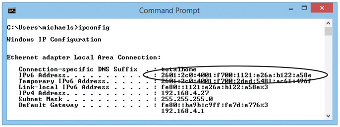
Figure 21-14 Windows system with a global IPv6 address
Let’s look at this process in detail with an example:
1. An IPv6-capable computer boots up. As it boots, it sends out a router solicitation message (FF02::2).
2. An IPv6-configured router hears the request and then sends to the computer a router advertisement containing the prefix and DNS. In this example, let’s say it is 2001:470:ABCD:1/64.
3. The computer takes the prefix and adds the EUI-64 or a random value to the end of the prefix. If the MAC address is 00-0C-29-53-45-CA, then the address is 20C:29FF:FE53:45CA.
4. Putting the prefix with the last half of the address, you get the following global address: 2001:470:ABCD:1:20C:29FF:FE53:45CA.
A global address is a true Internet address. If another computer is running IPv6 and also has a global address, it can access your system unless you have some form of firewall.
The addition of IPv6 makes programs such as ipconfig fairly complex. Take a look at Figure 21-15.

Figure 21-15 The ipconfig command with IPv6 and IPv4
Installing and Configuring a Wired Network
To have network connectivity, you need to have three things in place:
• Connected NIC The physical hardware that connects the computer system to the network media.
• Properly configured TCP/IP Your device needs correct TCP/IP setting for your network.
• Network client The interface that allows the computer system to speak to the protocol.
If you want to share resources on your PC with other network users, you also need to enable Microsoft’s File and Printer Sharing. Plus, of course, you need to connect the PC to the network switch via some sort of cable (preferably CAT 6 with Gigabit Ethernet cranking through the wires, but that’s just me!). When you install a NIC, by default Windows installs upon setup the TCP/IP protocol, the Client for Microsoft Networks, and File and Printer Sharing for Microsoft Networks. Mac OS X computers come fully set up for networking. Different Linux distros offer setup options similar to the Windows options.
Installing a NIC
The NIC is your computer system’s link to the network, and installing one is the first step required to connect to a network. NICs are manufactured to operate on specific media and network types, such as 1000BaseT Ethernet. Follow the manufacturer’s instructions for installation. If your system is of recent vintage, your motherboard almost certainly has a built-in NIC that you can disable in the BIOS. Assuming your OS has drivers for the new NIC, it will be detected, installed, and configured automatically. Your OS may have trouble installing drivers for a cutting-edge NIC without a functioning network connection; in that case, you’ll need removable media containing drivers from the manufacturer or downloaded from their Web site.
If, for some reason, Windows doesn’t automatically detect a new NIC after you turn the PC back on, go to Start | Control Panel | Add Hardware in Windows Vista or Start | Devices and Printers and click on Add a device in later versions of Windows to install it.
Full-Duplex and Half-Duplex
All modern NICs can run in full-duplex mode, meaning they can send and receive data at the same time. The vast majority of NICs and switches use a feature called autosensing to accommodate very old devices that might attach to the network and need to run in half-duplex mode. Half-duplex means that the device can send and receive, but not at the same time. An obvious example of a half-duplex device is the walkie-talkies you played with as a kid that required you to press and hold the orange button to transmit—at which time you couldn’t hear anything.
Link Lights
NICs made today have some type of light-emitting diode (LED) status indicator that gives information about the state of the NIC’s link to whatever is on the other end of the connection. Even though you know the lights are actually LEDs, get used to calling them link lights, because that’s the term all network techs use. NICs can have between one and four different link lights, and the LEDs can be any color. These lights give you clues about what’s happening with the link and are one of the first items to check whenever you think a system is disconnected from the network (see Figure 21-16).
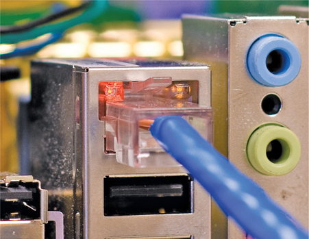
Figure 21-16 Mmmm, pretty lights!
Switches also have link lights, enabling you to check the connectivity at both ends of the cable. If a PC can’t access a network, always check the link lights first. Multi-speed devices usually have a link light that tells you the speed of the connection. In Figure 21-17, the light for port 2 on the top photo is orange, for example, signifying that the other end of the cable is plugged into either a 10BaseT or 100BaseT NIC. The same port connected to a Gigabit NIC—that’s the lower picture—displays a green LED.

Figure 21-17 Multispeed lights
A properly functioning link light is steady on when the NIC is connected to another device. No flickering, no on and off, just on. A link light that is off or flickering shows a connection problem.
Another light is the activity light. This little guy turns on when the card detects network traffic, so it makes an intermittent flickering when operating properly. The activity light is a lifesaver for detecting problems, because in the real world, the connection light sometimes lies to you. If the connection light says the connection is good, the next step is to try to copy a file or do something else to create network traffic. If the activity light does not flicker, you have a problem.
No standard governs how NIC manufacturers use their lights; as a result, LEDs in NICs come in an amazing array of colors and layouts. When you encounter a NIC with a number of LEDs, take a moment to try to figure out what each one means. Although different NICs have different ways of arranging and using their LEDs, the functions are always the same: link, activity, and speed.
Wake-on-LAN
A popular feature of most NICs is the ability to turn on or wake up a powered-down or sleeping PC. You’ll learn more about power management in Chapter 24, “Portable Computing,” but for now, know that Wake-on-LAN is handy when you want to wake up one or multiple computers that you aren’t physically near. To wake up a PC with Wake-on-LAN, you’ll need to use a second PC to send either a special pattern or a magic packet (a broadcast packet that essentially repeats the destination MAC address many times).
A powered-down or sleeping PC knows to look for this special pattern or packet, at least after configured to do so. Go to the Control Panel and open Network and Sharing Center. Click Manage network connections or Change adapter settings on the left. For all versions of Windows, right-click on the adapter and select Properties. Click the Configure button in the Properties dialog box and then select the Power Management tab (see Figure 21-18). To enable Wake-on-LAN, make sure the checkbox next to Allow this device to wake the computer is checked. Optionally, you can select Only allow a magic packet to wake the computer, which will instruct the NIC to ignore everything but magic packets.

Figure 21-18 Wake-on-LAN settings on the Power Management tab
Wake-on-LAN is very convenient, but it has one nasty downside. As noted in the Properties dialog box, Wake-on-LAN can wake up or turn on laptops using wireless connections, even when they aren’t plugged in or are inside a carrying case. Don’t let your laptop overheat or drain its battery—unless you know that you’ll need it, turn off Wake-on-LAN on your laptop.
QoS
Quality of service (QoS) enables busy networks to prioritize traffic. While we’ll look at QoS from the router’s perspective in Chapter 23, “The Internet,” individual systems play an important role in the QoS process by tagging their frames, enabling networking hardware to treat them according to rules defined by network administrators. Support for QoS tagging (or priority) should be enabled by default on most network adapters—but if you need to modify this setting you can find the Priority & VLAN option on the Advanced tab of your NIC’s Properties dialog box (see Figure 21.19).
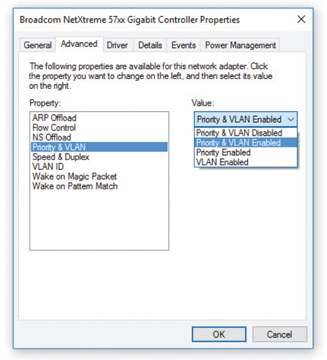
Figure 21-19 Network adapter Priority & VLAN setting
Configuring a Network Client
To establish network connectivity, you need a network client installed and configured properly. Let’s look at Microsoft’s client.
Installed as part of the OS installation, the Client for Microsoft Networks rarely needs configuration, and, in fact, few configuration options are available. To start it in Windows Vista, click Start, right-click Network, and select Properties. In Windows 7 and later, open the Control Panel and select Network and Sharing Center. Then click Manage network connections (Vista) or Change adapter settings (7/8/8.1/10) on the left.
In all versions of Windows, the next step is to right-click the Local Area Connection icon, click the Properties button, and highlight Client for Microsoft Networks. In Windows Vista, click the Properties button. Windows 7 and later disable this option. Note, however, that there’s not much to do here. Unless told to do something by a network administrator, just leave this alone.
Sharing and Security
Windows systems can share all kinds of resources across your network: files, folders, entire drives, printers, faxes, Internet connections, and much more. Conveniently for you, the scope of the CompTIA A+ certification exams is limited to sharing a system’s folders, printers, multifunction devices, and Internet connections. You’ll see how to share folders and printers now; multifunction devices are discussed in Chapter 26, “Printers and Multifunction Devices”; and Internet connection sharing is discussed in Chapter 23.
Network Shares
When you share over a network, every OS uses specific network sharing permissions to allow or restrict access to shared resources. These permissions do not have anything to do with file- or folder-level permissions like you find in Windows with NTFS (covered in Chapter 14, “Users, Groups, and Permissions”). But file- and folder-level permissions definitely affect share permissions. Here’s the scoop.
On a non-NTFS volume like an optical media disc or a flash-media USB drive, you only have three levels of permission: Read, Read/Write, and Owner, which are discussed later in this chapter. That’s because Microsoft uses NTFS for authorization with both local users and network users. So that means you use the network share to actually share the resource, but use NTFS to say what folks can do with that resource.
If you share a folder on an NTFS drive, as you normally do these days, you must set both the network permissions and the NTFS permissions to let others access your shared resources. Some good news: This is actually no big deal! Just set the network permissions to give everyone Full Control, and then use the NTFS permissions to exercise more precise control over who accesses the shared resources and how they access them. Open the Security tab to set the NTFS permissions.
Network Organization
Once a network is created using appropriate network technology like Ethernet, users need to be able to share resources in some organized fashion. Resources such as folders and printers need a way to determine who can and cannot use them and how they can be used. Microsoft designed Windows networks to work in one of three categories: workgroups, domains, or homegroups. (These are the Microsoft terms, but the concepts have been adopted by the entire computer industry and apply to Mac OS X and other operating systems.) These three organizations differ in control, number of machines needed, compatibility, and security.
Let’s start with the oldest and most common network organization: workgroups.
Workgroups
Workgroups are the most basic and simplistic of the three network organizations. They are also the default for almost every fresh installation of Windows.
By default, all computers on the network are assigned to a workgroup called WORK-GROUP. You can see your workgroup name by opening the System applet, as shown in Figure 21-20.

Figure 21-20 Default workgroup
There’s nothing special about the name WORKGROUP, except that every computer on the network needs the same workgroup name to be able to share resources. If you want to change your workgroup name, you need to use the System applet. Click the Change settings link to open the System Properties dialog box. Then click the Change button to change your workgroup name (see Figure 21-21).

Figure 21-21 Changing the workgroup name in advanced settings
Workgroups lack centralized control over the network; all systems connected to the network are equals. This works well for smaller networks because there are fewer users, connections, and security concerns to think about. But what do you do when your network encompasses dozens or hundreds of users and systems? How can you control all of that?
User Names and Passwords As you’ll recall from Chapter 14, when you log on to a Windows computer, you need to enter a user name and password. Windows makes this easy by giving you a pretty logon interface, as shown in Figure 21-22.

Figure 21-22 Windows logon screen
The user names and their passwords are stored in an encrypted format on your computer. User names have a number of jobs on your computer, but at this point the job most interesting to us is to give a user access to the computer. User names work well when you access your own computer, but these same user names and passwords are used to access shared resources on other computers in the network—and that’s where we run into trouble. To appreciate this problem, let’s watch a typical folder share take place on a network of Windows 7 systems.
Sharing a Folder All personal computers can share folders and printers out of the box. Sharing a folder in Windows is easy, for example. Just right-click on the folder and select Share with | Specific people to get to the File Sharing dialog box (see Figure 21-23). On Windows 7 systems, you’ll see options called Homegroup in the context menu—ignore these for now as all will be explained in the next section.

Figure 21-23 Folder Sharing with context menu
By default, you’ll see every user account that’s currently on this system. You may give an account Read or Read/Write permission, while the person who created the folder is assigned as Owner. The following list describes these permissions:
• Read You can see what’s in the folder. You may open files in the folder, but you can’t save anything back into the folder.
• Read/Write Same as Read but you can save files into the folder.
• Owner Same as Read/Write plus you can set the permissions for other users on the folder.
So all this sharing seems to work quite nicely, except for one big issue: When you log on to your computer, you are accessing a user name and database on that computer. The accounts you are giving access to are stored on your computer, so how do you give someone from another computer access to that shared folder? You have to give that other person a valid user name and password. We use the nomenclature <computer name>\<user name> to track our logons. If you log on to Computer A as Mike, we say you are logged on to ComputerA\Mike. This nomenclature comes in very handy when networked computers become part of the process.
Figure 21-24 shows Computers A and B. Assume there is a shared folder called Timmy on Computer A and the Mike account has Read/Write permission.

Figure 21-24 Computers A and B
A person fires up Computer B, logging in as Fred. He opens his Network menu option and sees Computer A, but when he clicks on it he sees a network password prompt (see Figure 21-25).

Figure 21-25 Prompt for entering user name and password
The reason is that the person is logged on as ComputerB\Fred and he needs to be logged on as ComputerA\Mike to successfully access this folder. So the user needs to know the password for ComputerA\Mike. This isn’t a very pretty way to protect user names and passwords. So what can you do? You have three choices:
1. You can make people log on to shares as just shown.
2. You can create the same accounts (same user name and same password) on all the computers and give sharing permissions to all the users for all the shares.
3. You can use one account on all computers. Everyone logs on with the same account, and then all shares are by default assigned to the same account.
Domains
Larger networks that need more control use domains. Opposite the decentralized nature of workgroups, domains require a specific server to control access to the network’s resources. This means tracking each user, each resource, and what each user can do to each resource.
To use a domain on a network of Windows machines, for example, you must have a computer running a version of Windows Server (see Figure 21-26). Windows Server is a completely different, much more powerful, and much more expensive version of Windows.

Figure 21-26 Windows Server
An administrator creates a domain on the Windows Server system, which makes that system the domain controller (DC). The administrator also creates new user accounts on the domain controller. These accounts are called domain accounts. Once a network is set up as a domain, each PC on the network needs to join the domain (which kicks you off the workgroup). When you log on to a computer that’s a member of a domain, Windows will prompt you for a user name instead of showing you icons for all the users on the network (see Figure 21-27).

Figure 21-27 Domain logon screen
When using a domain, you don’t log on to your computer. Instead, you log on directly to the domain. All user accounts are stored on the domain controller, as shown in Figure 21-28. A lot of domains have names that look like Web addresses, like totalhome.com, totalhome.local, or even just totalhome. Using the previous nomenclature, you can log on to a domain using <domain>\<domain user name>. If the domain totalhome. local has a user account called Mike, for example, you would use totalhome.local\Mike to log on.

Figure 21-28 Domain network
One of the best features of domains is that you can log on to any computer on the domain using the same domain account. You don’t have to set up local accounts on each computer. We call this feature single sign-on, and for most users, this is the biggest benefit to using a Windows domain.
Homegroups
The problem with workgroups is that they provide almost no security and require lots of signing on to access resources. Domains provide single sign-on and lots of security, but require special servers and lots of administration. To address this, Microsoft introduced a new feature in Windows 7 called HomeGroup.
HomeGroup uses the idea that people want to share data, not folders. Most people just want to share their music, not their My Music or Music folder. So homegroups skip folders completely and share your Windows libraries. A homegroup connects a group of computers using a common password—no special user names required. Each computer can be a member of only one homegroup at a time. Let’s make a homegroup and see how this works.
To make a homegroup, open the HomeGroup Control Panel applet. Assuming you currently connect to a workgroup and haven’t already created a homegroup, you’ll see a dialog box like the one shown in Figure 21-29.
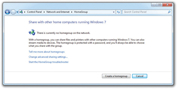
Figure 21-29 Default HomeGroup dialog box
Click the Create a homegroup button to create a homegroup. You’ll then see the Create a Homegroup dialog box shown in Figure 21-30.
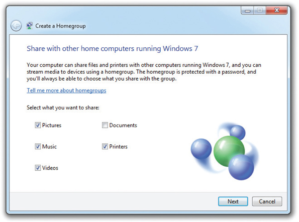
Figure 21-30 Create a Homegroup dialog box
Notice the five options: Pictures, Music, Videos, Documents, and Printers. The Documents checkbox is probably not checked, but go ahead and check it to share all five things. Click Next to see the homegroup’s password (see Figure 21-31).

Figure 21-31 The homegroup’s password
Perhaps you’ve heard that you shouldn’t write down passwords? Well, this password is so long that you might need to write it down. The dialog box even gives you a way to print it out! Click Next one more time to see the dialog box shown in Figure 21-32. This is the dialog box you will now see every time you click the HomeGroup applet in the Control Panel.

Figure 21-32 Homegroup configured
Let’s look at this carefully. Notice where it says Share libraries and printers and, a bit lower, How do I share additional libraries? By default, homegroups share libraries, not individual folders. The Music, Pictures, Videos, and Documents libraries are shared by default. Although printers get their own checkbox, this setting remains the same as a normal printer share. It’s just a handy place to add printer sharing, as even the most basic users like to share printers.
Once you’ve created a homegroup, go to another computer on the network and open the HomeGroup Control Panel applet. Assuming all the factors stated earlier, you will see a dialog box like Figure 21-33.
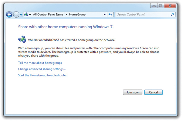
Figure 21-33 HomeGroup showing an existing homegroup
Click the Join now button, enter the password, choose which libraries you want to share with everyone else, and the new computer is in the homegroup!
Access the files shared through a homegroup by opening Windows Explorer or File Explorer, as shown in Figure 21-34. To see what others are sharing, select the corresponding computer name. You can then open those libraries to see the shared folders.

Figure 21-34 Using homegroups
Sharing more libraries is easy, and, if you’d like, you can even share individual folders. Just right-click on the library or folder and select Share with, as shown in Figure 21-35.

Figure 21-35 The Share with menu
Notice you have four options: Nobody, Homegroup (Read), Homegroup (Read/Write), and Specific people. The Nobody option means the item is not shared.
By sharing libraries with homegroups, Microsoft hides folders for most users, helping users share their stuff (documents, pictures, music, and videos) instead of folders. Home-groups fit a very specific world—smaller, non-domain home networks—but within that realm, they work wonderfully.
Sharing Printers
Sharing printers in Windows follows the same process as sharing drives and folders. Assuming that the system has printer sharing services loaded, in Windows Vista go to the Printers folder in the Control Panel or Start menu and right-click the printer you wish to share. Select Sharing, and then click Share this printer and give it a name. In Windows 7/8/8.1/10, open Devices and Printers in the Control Panel, right-click on the printer you wish to share, select Printer properties, and then select the Sharing tab (see Figure 21-36). From here it’s just like Vista—click Share this printer and you’re done.

Figure 21-36 Giving a name to a shared printer on Windows 8.1
One of the most pleasant aspects of configuring a system for networking under all versions of Microsoft Windows is the amazing amount of the process that is automated. For example, if Windows detects a NIC in a system, it automatically installs the NIC driver, a network protocol (TCP/IP), and Client for Microsoft Networks. So if you want to share a resource, everything you need is automatically installed. Note that although File and Printer Sharing is also automatically installed, you still must activate it by clicking the appropriate checkbox in the Local Area Connection Properties dialog box.
Troubleshooting Networks
Once you go beyond a single PC and enter the realm of networked computers, your troubleshooting skills need to take a giant leap up in quality. The secret to finding the right answer to networking problems on the CompTIA A+ exams is to remember that the exams only ask about the skills to get a single computer back on the network. Granted, this might mean you’ll need to check a switch or verify another system’s connectivity, but in general, always focus your network troubleshooting answers on getting a single system up and running.
CompTIA likes to ask questions that deal with “no connectivity” or “intermittent connectivity.” There are two ways to look at connectivity issues, and CompTIA A+ exam objectives don’t specify which type is covered on the exams. The first type of connectivity issue (and probably the one CompTIA means) is when your computer loses physical connectivity. The second type is when you’re on the network and can’t access a particular resource (you can access other resources, just not the one you want right now). Let’s consider both.
Repairing Physical Cabling
“The network’s down!” is one of the most terrifying phrases a network tech will ever hear. Networks fail for many reasons, and the first thing to know is that good-quality, professionally installed cabling rarely goes bad, but you need to know what to do when it does. Let’s take a moment now to discuss what to do when you think you’ve got a problem with your physical network.
Symptoms
Physical connectivity interruptions stand out in Windows. Windows displays a red X over the network icon in the notification area to show you’re not connected (see Figure 21-37).
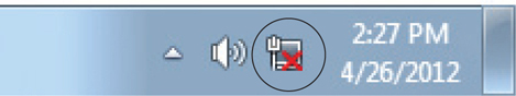
Figure 21-37 Windows 7 red X error notification icon
If you encounter this problem, first check the obvious: Is the cable unplugged at your system? At the wall outlet? Then go for the less obvious: Is the NIC disabled in Device Manager? If these checks don’t solve the problem, take a peek on the other side of the cable. If you’re not connected to a running switch, you’re going to get the disconnect errors.
Intermittent connectivity is often the same issue but typically is harder to figure out. Either way, read the next section to see how to get serious about testing for these pesky connectivity problems.
Diagnosing Physical Problems
Look for errors that point to physical disconnection. A key clue that the computer may have a physical problem is that a user gets a “No server is found” error, or tries to use the operating system’s network explorer utility (like Network in Windows) and doesn’t see any systems besides his or her own.
Multiple systems failing to access the network often points to hardware problems. This is where knowledge of your network cabling helps. If all the systems connected to one switch suddenly no longer see the network, but all the other systems in your network still function, you not only have a probable hardware problem, but also have a suspect—the switch.
Check the Lights
If you suspect a hardware problem, first check the link lights on the NIC and switch. If they’re not lit, you know the cable isn’t connected somewhere. If you’re not physically at the system in question (if you’re on a tech call, for example), you can have the user check his or her connection status through the link lights or through software.
If the problem system clearly cannot connect, eliminate the possibility of a failed switch or other larger problem by checking to make sure other people can access the network, and that other systems can access the shared resource (server) that the problem system can’t see. Inspect the cable running from the back of the computer to the outlet. Finally, if you can, plug the system into a known-good outlet and see if it works. A veteran network tech keeps a long patch cable for just this purpose. If you get connectivity with the second outlet, you should begin to suspect the structured cable running from the first outlet to the switch. Assuming the cable is installed properly and has been working correctly before this event, a simple continuity test will confirm your suspicion in most cases.
Check the NIC
Be warned that a bad NIC can also generate a “can’t see the network” problem. Use the utility provided by the OS to verify that the NIC works. If you’ve got a NIC with diagnostic software, run it—this software will check the NIC’s circuitry. The NIC’s female connector is a common failure point, so NICs that come with diagnostic software often include a special test called a loopback test. A loopback test sends data out of the NIC and checks to see if it comes back. Some NICs perform only an internal loopback, which tests the circuitry that sends and receives, but not the actual connecting pins. A true external loopback requires a loopback plug inserted into the NIC’s port (see Figure 21-38). If a NIC is bad, replace it.

Figure 21-38 Loopback plug
Cable Testing
The vast majority of network disconnection problems occur at the work area. If you’ve tested those connections, though, and the work area seems fine, it’s time to consider deeper issues.
With the right equipment, diagnosing a bad horizontal cabling run is easy. Anyone with a network should own a midrange time-domain reflectometer (TDR) tester such as the Fluke MicroScanner. A TDR measures impedance in network cabling. If the tester measures any impedance, something is wrong with the cable. With a little practice, you can easily determine not only whether a cable is disconnected but also where the disconnection takes place. Sometimes patience is required, especially if you’ve failed to label your cable runs, but you will find the problem.
When you’re testing a cable run, always include the patch cables as you test. This means unplugging the patch cable from the PC, attaching a tester, and then going to the telecommunications room. Here you’ll want to unplug the patch cable from the switch and plug the tester into that patch cable, making a complete test, as shown in Figure 21-39.
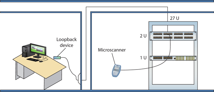
Figure 21-39 Cable tester in action
Testing in this manner gives you a complete test from the switch to the system. In general, a broken cable must be replaced. A bad patch cable is an easy fix, but what happens if the horizontal cable is to blame? In these cases, I get on the phone and call my local installer. If a cable is bad in one spot, the risk of it being bad in another is simply too great to try anything other than total replacement.
Toners
It would be nice to say that all cable installations are perfect and that over the years they won’t tend to grow into horrific piles of spaghetti-like, unlabeled cables. In the real world, though, you might eventually find yourself having to locate or trace cables. Even in the best-planned networks, labels fall off ports and outlets, mystery cables appear behind walls, new cable runs are added, and mistakes are made counting rows and columns on patch panels. Sooner or later, most network techs will have to be able to pick out one particular cable or port from a stack.
When the time comes to trace cables, network techs turn to a device called a toner for help. Toner is the generic term for two separate devices that are used together: a tone generator and a tone probe. The tone generator connects to the cable using alligator clips, tiny hooks, or a network jack, and it sends an electrical signal along the wire at a certain frequency. The tone probe emits a sound when it is placed near a cable connected to the tone generator. These two devices are often referred to by the brand-name Fox and Hound, a popular model of toner made by the Triplett Corporation (see Figure 21-40).
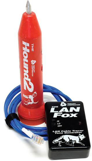
Figure 21-40 Fox and Hound
To trace a cable, connect the tone generator to the known end of the cable in question, and then position the tone probe next to the other end of each of the cables that might be the right one. The tone probe makes a sound when it’s placed next to the right cable. Some toners have one tone probe that works with multiple tone generators. Each generator emits a separate frequency, and the probe sounds a different tone for each one. Even good toners are relatively inexpensive ($75 or so); although inexpensive toners can cost less than $25, they don’t tend to work well, so spending a little more is worthwhile. Just keep in mind that if you have to support a network, you’d do best to own a decent toner.
Fixing Common Problems
Let’s go back and look at the second possible meaning for a loss in connectivity. It’s very common to try to connect to a shared resource and either fail or find that a shared resource you’ve used time and again has suddenly disappeared.
Failing to Connect to a New Resource
When you can’t connect to a resource on the first try, it often points to a configuration issue. In most cases, a quick double-check of the sharing system will reveal one of the following problems (and call for the associated solution):
• You don’t have the right share name? Go check at the serving system.
• You don’t have the required user name/password? Ask someone who might have this knowledge, or double-check that your account has access.
• You don’t have permission to use/access/connect to the shared resource? Make sure you have the correct permissions.
• You’re not on the right homegroup/domain/workgroup? Check your system and the sharing system to verify which workgroup/domain name to use. On a homegroup, make sure you’ve used the proper password.
• The folder or printer isn’t shared? Share it!
• The folder or printer doesn’t exist? Make sure the serving system still hosts the folder you want. Install the network printer if you haven’t yet.
Failing to Connect to a Previously Used Resource
If you suddenly can’t connect to a resource that you’ve used many times before, go with the easy answers first:
• Check that you can see the resource using Network.
• Check that the serving system is on.
• Check that the computer is physically connected to the serving system.
The net Command
Windows enables you to view a network quickly from the command line through the net command. This works great when you plug into a network for the first time and, naturally, don’t know the names of the other computers on that network. To see the many options that net offers, type net at a command prompt and press ENTER. The view and use options offer excellent network tools.
You can think of net view as the command-line version of Network. When run, net view returns a list of Windows computers on the network:
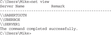
Once you know the names of the computers, you type net view followed by the computer name. The net view command will show any shares on that machine and whether they are mapped drives:

The net use command is a command-line method for mapping network shares. For example, if you wanted to map the Research share shown in the previous example to the X: drive, you simply type

This will map drive X: to the Research share on the SERVER1 computer.
The nbtstat Command
The nbtstat command is an old command-line utility that predates Windows. It stands for NetBIOS over TCP/IP Statistics. Many versions ago, Windows used NetBIOS for many aspects of LAN file sharing, and even though NetBIOS is long gone, bits of Net-BIOS hang on as a way for Windows to resolve host names on the network when a DNS server is not available.
While not as useful as it once was, nbtstat can still provide insight when troubleshooting naming issues in small workgroups. Here are a couple of usage examples. To see what your computer’s NetBIOS name is, use the nbtstat –n command.


You can also query a remote machine by IP to find out its NetBIOS name with nbtstat –A (note the upper case “A”, use a lowercase “a” if you know the machines NetBIOS name already).

Finally, you can see all the names that NetBIOS has in its local cache with nbtstat –c.

Because the cache is temporary, you may find that it is empty if you haven’t browsed your LAN or interacted with another machine recently.
Chapter Review
Questions
1. Steven’s Windows system can’t connect to the Internet, and he comes to you, his PC tech, for help. You figure out that it’s a DHCP problem. What program should you run to troubleshoot his DHCP problem from the client side?
A. ipconfig
B. ifconfig
C. config
D. dhcp /review
2. What command would you use to view the path taken by an Ethernet packet?
A. ping
B. ipconfig
C. tracert
D. nslookup
3. Which of the following is the correct net syntax for discovering which network shares on a particular server are mapped on your computer?
A. net view \\fileserver
B. net \\fileserver
C. net map \\fileserver
D. net share \\fileserver
4. What small device enables you to test a NIC’s circuitry?
A. Loopback plug
B. Port tester
C. Multimeter
D. Integrated network and logic probe
5. Which command can be used to display the cached NetBIOS names for a Windows system?
A. nslookup
B. dig --cache
C. nbtstat -c
D. nbtstat -a
6. You are down under your desk organizing some wires when you notice that the activity light on your NIC is blinking erratically. Is there a problem?
A. Yes, the activity light should be on steadily when the computer is running.
B. Yes, the activity light should be blinking steadily, not randomly.
C. No, the light blinks when there is network traffic.
D. No, the light blinks to show bus activity.
7. What is a common symptom of a bad network cable?
A. Rapidly blinking link lights
B. No link lights
C. Solid on link lights
D. Steady blinking link lights
8. What command-line utility would you run to show a list of network computers?
A. net send
B. show net_servers
C. net use
D. net view
9. What benefit does full-duplex offer?
A. It enables NICs to send and receive signals at the same time.
B. It enables NICs to send data twice as fast.
C. It enables NICs to receive data twice as fast.
D. It enables a switch to connect to both coaxial and fiber optic cables.
10. What do most techs call a toner or tone generator?
A. TDR
B. UTP
C. UDP
D. Fox and Hound
Answers
1. A. You should run ipconfig, or more specifically ipconfig /release and then ipconfig /renew to get a new IP address if a DHCP server is available for Steven’s Windows system. This typically resolves most DHCP client-side problems. ifconfig is the program used by Mac OS X and Linux systems for this task. Neither config nor dhcp is valid.
2. C. The tracert command in Windows traces the path a data packet takes to get to its destination. Mac OS X and Linux use the traceroute utility for similar purposes.
3. A. To see the network shares mapped on your computer, use net view \\fileserver.
4. A. A loopback plug will test the NIC’s Ethernet port and circuitry.
5. C. Nslookup and dig only work with DNS, not NetBIOS. Nbtstat -a is for querying a remote system’s name, but nbtstat -c displays the cached names.
6. C. The lights should be blinking to show activity—this is normal.
7. B. If there are no link lights, you probably have a bad network cable.
8. D. Use the net view command to show a list of computers on the network.
9. A. Full-duplex technology enables NICs to send and receive signals at the same time.
10. D. Most techs refer to a toner or tone generator as a Fox and Hound, the name of a popular brand of tone generator.


