 since 2x2 – x – 6 = (x – 2) (2x + 3).
In this chapter we powerfully extend the possibilities of what we can do with our number system. This extension leads us to simpler ways of finding mathematical rules. It also has many very important physical applications.
The chapter is divided into the following sections.
(a) Finding the missing roots,
(b) Finding roots for all quadratic equations,
(c) Modulus and argument (or mod and arg for short)
10.B Doing arithmetic with complex numbers
(b) Multiplication of complex numbers,
(c) Dividing complex numbers in mod/arg form,
(d) What are complex conjugates?
(e) Using complex conjugates to simplify fractions
10.C How e connects with complex numbers
(a) Two for the price of one – equating real and imaginary parts,
(c) What is the geometrical meaning of z = ejθ?
(d) What is e−jθ and what does it do geometrically?
(e) A summary of the sin/cos and sinh/cosh links,
(g) Another example: writing cos 5θ in terms of cos θ,
(h) More examples of writing trig functions in different forms,
(i) Solving a differential equation which describes SHM,
(j) A first look at how we can use complex numbers to describe electric circuits
10.D Using complex numbers to solve more equations
(a) Finding the n roots of zn = a + bj,
(b) Solving quadratic equations with complex coefficients,
(c) Solving cubic and quartic equations with complex roots
10.E Finding where z can be if it must fit particular rules
(a) Some simple examples of paths or regions where z must lie,
(b) What do we do if z has been shifted?
(c) Using algebra to find where z can be,
(d) Another example involving a relationship between w and z
So far, we have been able to show all of the answers or roots of the equations which we have been able to solve as points on the horizontal axis of a graph. If we write the equation as f(x) = 0, then its solutions are where the curve of y =f(x) cuts the x-axis, so that y = 0.
These solutions or roots have included different kinds of numbers. For example:
(a) 2x2 – x – 6 = 0 has the two roots x = 2 or x =  since 2x2 – x – 6 = (x – 2) (2x + 3).
(b) x2 – 4x – 1 = 0 has the two roots x = 2 ±  , using the quadratic formula from Section 2.D.(d).
(c) 2x3 – x2 – 5x – 2 = 0 has the three roots  , x = 2 and x = – 1 since 2x3 – x2 – 5x – 2 = (2x + 1) (x – 2) (x + 1).
(d) 4x4 – 5x2 + 1 = 0 has the four roots of x = 1, x = –1,  and
and  since 4x4 – 5x2 + 1 = (x – 1)(x + 1)(2x – 1) (2x + 1).
In order to have all these solutions, we have had to extend the system of counting numbers 1, 2, 3, 4, . . . to include negative numbers, fractions, and numbers like  which can’t be written as fractions. I described all these different kinds of numbers in Section 1.E. Together, they make up what are known as the real numbers. We can think of the horizontal axis of a graph as a number line which contains all the solutions to equations like (a), (b), (c) and (d) above.
But we have also found that sometimes equations which look as though they ought to have solutions, such as x2 – 2x + 2 = 0, have no solution given by any number which we can find on the x-axis. It appears that sometimes the number of solutions tallies with the highest power of x, as in the four examples of (a), (b), (c) and (d) above, but sometimes this doesn’t seem to work. This peculiar situation is shown particularly clearly by what seem at first sight to be the simplest possible equations of this kind.
We know that the equation x2 = 1 has the two solutions or roots of x = +1 or x = –1.
However, the equation x3 = 1, unlike (c) above with its three solutions, only has the one solution of x = 1.
The equation x4 = 1 again has the two solutions of x = +1 or x = –1.
With x5 = 1, we are back to just the one solution of x = 1.
As we take higher powers of x, this pattern will continue, with just one solution of x = +1 for odd powers, and the two solutions of x = +1 or x = –1 for even powers.
This is somehow not very satisfying; would it not feel more correct if x2 = 1 had two roots, x3 = 1 had three roots, x4 = 1 had four roots and so on? But where would they be? How could we widen our number system so that we would have these extra roots or solutions?
Suppose we take the horizontal axis out of the graph paper, and lay it out separately as a number line which contains all the roots of the equations which we can so far solve, including equations (a), (b), (c) and (d) above. This number line, which I have drawn in Figure 10.A.1, shows all the real numbers. (The arrows are there to show that this line can be infinitely extended in either direction.)

Figure 10.A.1
Now imagine that we are looking down on this number line and seeing all these roots. We are also seeing the various roots of x = +1 and x = –1 for the equations xn = 1. (We see both +1 and –1 if n is even, and just +1 if n is odd.)
If we take the particular case of x4 = 1, we have x = +1 and x = –1 as two of its roots. If we want this equation to have four roots, where could we think of the other two roots as being?

Suppose we think that up to now we have just seen the possible answers through a slit which allows us to see the number line of Figure 10.A.1. Sometimes this has meant that we could see all the possible solutions to an equation and sometimes it has meant that there are solutions which are somehow off to the side so that they are hidden from us. If so, it seems reasonable that the four roots of x4 = 1 should be symmetrically placed. This would give us the four roots (a) (b) (c) and (d) which I have shown in Figure 10.A.2(a).
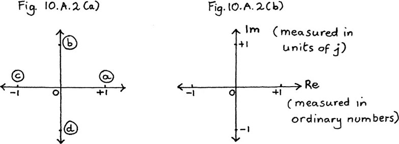
Figure 10.A.2
It seems a good idea that the two roots on the vertical axis should also be placed one unit away from O. But what are they?
They would have to be two different numbers, each of which multiplied by itself four times would give the answer of +1.
We know that (–1)2 = +1, so if we can somehow think of the vertical axis as showing units of  , as the horizontal axis shows units of
  , we shall be able to have the four roots which we would like.
Each root is one unit away from the origin, so root (b) would be  and root (d) would be
If we now let ourselves say that  , the two extra roots will work in the following way.
For (b), we shall have

For (d), we shall have

like (b), since each pair of minuses multiplied gives a plus.
To emphasise that we have invented a new number here, which needs a separate direction of its own to show it, we shall call  by the letter j.
We are defining a new number j such that j2 = –1 so  .
.
We can now write the four roots of x4 = 1 as x = +1, x = –1, x = j and x = –j with each of these roots being one unit away from the origin. I show them in Figure 10.A.2(b).
The horizontal axis shows the real numbers (just like any ordinary x-axis) so it is called the real axis and labelled Re instead of x.
The numbers shown on the vertical axis, which are measured in units of j, are called imaginary numbers. (This curious name is for historical reasons.) We therefore call the vertical axis the imaginary axis and label it Im instead of y.
Figure 10.A.2(b) is an example of what is called an Argand diagram. It is named after the Swiss mathematician who first thought of showing complex numbers in this way.
Mathematicians often use i rather than j for  . However, physicists and engineers usually use j, because imaginary numbers have important physical applications in the study of electric circuits where the letter i is often used for current.

Can you draw a sketch showing where you think the eight roots of x8 = 1 might be? We shall come back to this at the end of Section 10.B.(b).
Next we shall find out whether having this new number j will make it possible for us to find solutions for all quadratic equations.
Suppose we take as an example the equation x2 – 8x + 25 = 0.
It is usual to use z instead of x if we are extending the possibilities for roots by using these new numbers, so I shall rewrite this equation as z2 – 8z + 25 = 0.
Now we see what happens if we use the quadratic formula. Using z, this formula says
If az2 + bz + c = 0 then  (Section 2.D.(d))
Here, we get

so
z = +4 ± 3  giving z1 = 4 + 3j and z2 = 4 – 3j
using our new number j for  , and calling the roots z1 and z2.
(Try checking for yourself whether you think each of these two roots do fit the equation by substituting each of them back into the equation in turn and seeing what happens.)
Notice that the two roots which we now have for this equation are each made up of two parts, the +4 which is a real number, and the 3j which is then either added or subtracted. We can show these two roots on the same sort of diagram that we used in Figure 10.A.2(b), with the real parts lying along the horizontal or real axis, and the imaginary parts lying along the vertical or imaginary axis. I have drawn this particular pair of roots in Figure 10.A.3.
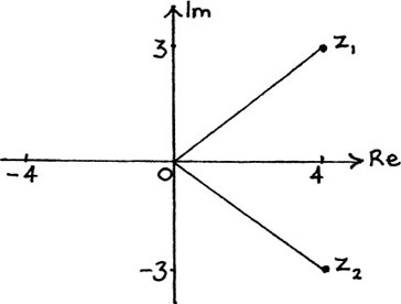
Figure 10.A.3
Notice that they have the property that they are symmetrically placed either side of the real axis. We shall look at the special properties of pairs like this in Section 10.B.(d).
I shall now use the number 4 – 3j shown in Figure 10.A.3 to give you some definitions.
A number like 4 – 3j is called a complex number.
4 is called its real part and –3 is called its imaginary part.
The number 4 gives the measurement along the real axis.
The number –3 gives the measurement along the imaginary axis.
If z = 4 – 3j then we say Re (z) = 4 and Im (z) = –3.
(Notice that the imaginary part tells us how many units of j we have; it does not actually include the j.)
Solve the following equations writing your answers in the same way that we used in the example above. (This is called writing them in the form a ± bj.)
Show each pair of roots on a separate Argand diagram. Save these answers and sketches as you will need them for the next exercise.
(If you feel shaky about  being the same as 6, or
  being the same as
  you should read through Section 1.F.(c) and then do Exercise 1.F.3 before continuing.)
(1) z2 – 2z + 2 = 0
(2) z2 – 4z + 13 = 0
(3) z2 + 4z + 5 = 0
(4) z2 + 2z + 6 = 0
In the last section, we found that the two roots of the equation z2 – 8z + 25 = 0 are z1 = 4 + 3j and z2 = 4 – 3j and I showed them on the Argand diagram of Figure 10.A.3. In Figure 10.A.4, I show an alternative way of describing the positions of z1 and z2 on an Argand diagram. Instead of using the pairs of coordinates given by their real and imaginary parts, we can use two other measurements.
The first of these is their lengths which I have labelled |z1| and |z2| on the diagram.
The length of a complex number is called its modulus or mod, and it is written as mod z or |z|.
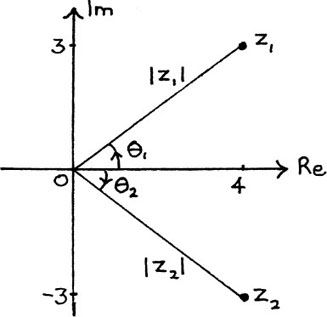
Figure 10.A.4
From Figure 10.A.4 we see that  by Pythagoras’ Theorem.
Also |z2| = |z1|, since 
For any complex number z = x + yj we have the following definition.
The modulus or length of the complex number z = x + yj is given by  . Because |z| is a length, it is always positive.
If we want to talk about more than one modulus, we call them moduli and not moduluses. (This is because ‘modulus’ is a Latin word.)
To draw a complex number z on an Argand diagram it will not be enough just to know its length. We can see this in the example above where both z1 and z2 have the same length. In order to describe them fully, we also need to know the direction in which we should draw them. This direction can be described by using the angles turned through from the positive real axis to get to each of them. I have called these two angles θ1 and θ2 on Figure 10.A.4. In this particular example, these two angles are equal in size, but are turning in opposite directions from the positive real axis.
The angle turned through from the positive real axis to give a complex number, z, is called its argument.
It is written as arg z.
An anticlockwise turn gives a positive angle.
A clockwise turn gives a negative angle.
Here,
|
arg z1 = θ1 = |
= 0.644 radians to 3 d.p. |
and |
arg z2 = θ2 = |
= –0.644 radians to 3 d.p. |
Writing this pair of angles in this way shows their symmetry very nicely. It is true that we could also get to the same position of z2 by turning the other way. This would give an angle  radians to 3 d.p. but this hides the symmetry of θ1 and θ2, coming from the symmetrical pair of 4 ± 3j.
For this reason we give this further definition.
The principal value of the argument of a complex number z lies between – π and π, so that – π < θ ≤ π.
Therefore, the values I have given above for θ1 and θ2 are the principal values for the arguments of z1 and z2.

It is rather easy to make mistakes when finding the arguments of complex numbers if you use a calculator to find tan–1 θ. The following example shows why this is.
We will find the mod and arg of the pair of solutions to the equation z2 + 2z + 4 = 0. Using the formula gives

I show the pair of roots  and
and  in Figure 10.A.5.
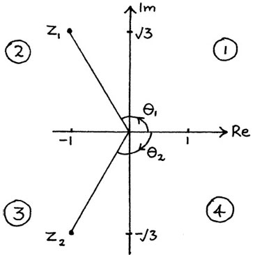
Figure 10.A.5
We have
 and
and 
We can also see from the diagram that

and

But if you had used  to find θ1 you would have got –π/3 which is an angle in the fourth quadrant, and so not the right place at all. To remind you where each quadrant is, I have labelled them in the diagram above as (1), (2), (3) and (4).
Similarly, if you had said  , you would have got the angle of π/3 in the first quadrant which is again the wrong place. The problem is that the function tan–1 is only defined for the range from π/2 to + π/2. (We saw why this is in Section 5.A.(i).)
In this particular example, you could of course find θ2 from its symmetry with θ1.
You should always draw a little sketch of what is happening when finding arguments so that you don’t get them in the wrong place.
(To help you to check your answers, remember that there are roughly 3 radians in a half-turn of π, and one radian is roughly 60°.)
A shorthand version which is often used to write a complex number z in mod/arg form, is to write z as [r, θ] where r = |z| and θ = arg z. In the example above, we would have z1 = [2, 2π/3] and z2 = [2, – 2π/3].
Another shorthand version, which is often used by engineers, is to write  instead of [r, θ].

r and θ can be used instead of x and y in any graph. If the graph is not an Argand diagram, then θ is measured between 0 and 2π. r and θ are called polar coordinates and x and y are called Cartesian coordinates. This name is after the French mathematician and philosopher, Réné Descartes, who is also famous for having said ‘Cogito ergo sum’ or ‘I think, therefore I am’.
What is the connection between z = x + yj and z = [r, θ]?
I show this in Figure 10.A.6.
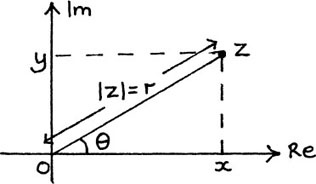
Figure 10.A.6
From this diagram, we see the following pair of results.
x = |z| cos θ = r cos θ and y = |z| sin θ = r sin θ.
So z = x + yj = r (cos θ + j sin θ).
Looking back, you will see that these relationships are true for all the diagrams wherever z is. The size of θ automatically takes care of the signs of x and y. We are making use here of the definitions for the sin and the cos of angles greater than π/2. These came from the turn of a unit length about the origin (in Section 5.A.(c)), so they are very much related to what we are doing now.
In each of the following questions, give the arguments in radians correct to 2 d.p. unless they are an exact fraction of π.
(1) Find the modulus and argument of each of the following complex numbers.
(b) –2
(c) 2j
(d) –5j
(e) 5 + 12j
(f) –5 – 12j
(g) 7 – 24j
(h) –7 + 24j
(j) –1 – j
(2) Figure 10.A.2(b) in Section 10.A.(a) shows the four roots of z4 = 1. What is the modulus and argument of each of these?
(3) Find the modulus and argument for each of the pairs of roots of the quadratic equations which you solved in Exercise 10.A.1. Use your sketches of these roots to make sure that your arguments are in the right place.
When we do arithmetic with these numbers, we assume that each separate part of them, the real and the imaginary, behaves within itself according to the usual rules for numbers. The only extra property is that these two tracks of numbers are not forever running beside each other with no communication; every time we get a j2 we get a cross-over from the imaginary to the real. In fact, any even power of j will do this. This makes their possibilities much more interesting.
Suppose we have two complex numbers z1 = 3 + j and z2 = 2 + 5j.
Since each number is made up of two separate independent measurements, we add the numbers by adding each of these pairs, giving us (3 +j) + (2 + 5j) = 5 + 6j.
The order of addition will not matter because (2 + 5j) + (3 + j) = 5 + 6j also.
We can show this addition on an Argand diagram if we allow ourselves to shift the second number. (See Figure 10.B.1(a).)
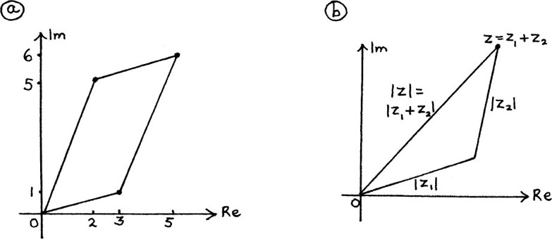
Figure 10.B.1
The two separate displacements of (2 + 5j) and (3 + j) add together to give the single displacement of (5 + 6j). We see that the final result is the same whichever order we do the addition in – we just get there by a different route. These two different routes put together make a parallelogram.
To add two complex numbers together, we add the real parts and the imaginary parts separately.
For example, (3 – 2j) + (5 + 4j) = 8 + 2j.
Subtracting complex numbers works equally easily.
To subtract two complex numbers we subtract the real parts and the imaginary parts separately.
For example, (4 + 3j) – (1 – 2j) = 3 + 5j.
If we have any three complex numbers z, z1 and z2 so that z = z1+ z2, and we draw them on an Argand diagram, we can see a useful relationship between their lengths. I show this in Figure 10.B.1(b) above.
Since the length of the third side of a triangle must be shorter than the lengths of the other two sides added together (unless the triangle is squashed completely flat, when side (3) = side (1) + side (2)), we have the following result.
If z = z1 + z2 then |z| ≤ |z1| + |z2|, that is, |z1 + z2| ≤ |z1| + |z2|.
We could show the addition of any quantity of complex numbers on an Argand diagram. The resulting final displacement will give the sum of the complex numbers.
I show an example of this in Figure 10.B.2 where the sum of the complex numbers is zero. We have (4 + j) + (2 + 3j) + (– 3 + 2j) + (– 3 – 6j) = (0 + 0j).
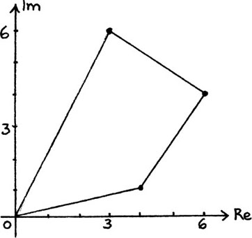
Figure 10.B.2
EXERCISE 10.B.1
This is also the way in which the addition of vectors works. Vectors are quantities which have both magnitude and direction. Complex numbers have direction built into them because of their structure of two separate parts written in a particular order.
If z1 = 3 + 5j and z2 = – 2 + 2j and z3 = – 7 – 2j find the following.
(1) z1 +z2
(2) z1 +z2 + z3
(3) z2 – z3
Multiplying by a positive number or scalar
If a complex number is multiplied by a positive number, the effect is to change its size by the scale given by this number.
For example,
3(2 + j) = 6 + 3j and  (4 + 2j) = 2 + j.
I show these in Figure 10.B.3. The numbers 3 and  have no direction themselves. They simply enlarge or shrink the two complex numbers.

Figure 10.B.3
Multiplying two complex numbers together
Again we use the ordinary rules of arithmetic on the separate parts of the two numbers.
To multiply two complex numbers together we multiply out the brackets in the usual way except that we replace j2 by –1.
For example,
(3 + 4j × (12 + 5j) = 36 + 48j + 15j + 20j2 = 16 + 63j.
The above example does not seem to show any particular pattern, but there are two very nice links between the three numbers z1 = (3 + 4j), z2 = (12 + 5j) and z1z2= 16 + 63j.
Work out for yourself the values of |z1|, |z2| and |z1z2|, and see if you can spot the first link.

You should have  and
and  and
and  so
so  .
.
Now work out for yourself arg z1, arg z2 and arg (z1z2) and again see if you can spot a link between them.
You should have  rad to 3 d.p. and
  rad to 3 d.p. and arg
  rad to 3 d.p.
It looks as though arg z1 + arg z2 = arg (z1z2).
We can see that this is exactly so by using the rule
 from Section 5.D.(c).
Putting A = argz1 and B = arg z2 we get tan  and tan
  So
So

therefore
arg(z1z2) = arg z1 + arg z2.
Multiplying complex numbers in mod/arg form
Is the result which we have just found above a special coincidence because of our particular choice of z1 and z2 or is there a reason why they should behave like this?
We show that there is an underlying reason for this result by taking any two complex numbers z1 and z2 and writing them in modulus/argument form.
To do this, we let |z1| = r1 and arg z1 = θ1 so z1 = r1 (cos θ1 +j sin θ1), and |z2| = r2 and arg z2 = θ2 so z2 = r2(cos θ2 + j sin θ2).
Then

We can replace the real and imaginary parts of the inside of this bracket using the double angle rules of Section 5.D.(b). This gives us
z1z2 = r1r2 (cos(θ1 + θ2) + j sin(θ1 + θ2)).
We now have a very neat way of working out the result of multiplying two complex numbers together.
To multiply two complex numbers together we multiply their moduli and add their arguments.
As an example, we’ll take the two roots z1 = 4 + 3j and z2 = 4 – 3j of the quadratic equation z2 – 8z + 25 = 0. Multiplying them together, we get
z1z2 = (4 + 3j) (4 – 3j) = 16 + 12j – 12j – 9j2 = 25.
We also know from Section 10.A.(c) that |z1| = |z2| = 5 and arg z1 = 0.644 radians while arg z2 = –0.644 radians.
Multiplying the two moduli gives us 25, and adding the two arguments, taking account of their signs, gives us zero, so both ways of multiplying give us the same answer which is the real number of 25.
Notice that this answer agrees with the rule of Section 2.D.(e) which says that the product of the roots of a quadratic equation is given by c/a. (Here, c = 25 and a = 1.)
The sum of the roots also agrees with the rule given there, since (4 + 3j) + (4 – 3j) = 8 = – b/a. (Here, b = –8.)
These two rules continue to work for quadratic equations with complex roots for exactly the same reason which we found they worked in Section 2.D.(e). The square root of b2 – 4ac, which is where potential problems can arise, cancels out when the roots are added or multiplied.
The geometrical effect of multiplying complex numbers
It is now very easy for us to see geometrically what happens to complex numbers when they are multiplied together.
In particular, if we return to the equation z4 = 1 in Section 10.A.(a), and its solutions shown in Figure 10.A.2, we see that multiplying j by itself turns it through 90° or π/2. Multiplying this result by j turns it through another right angle.
A final multiplication by j makes the last turn through 90° to finish at +1. We see geometrically that j4 = +1.
The next root of z = –1 turns through 180° when it is multiplied by itself, which brings it to +1. Repeating this process takes it through a full circle again to +1.
Think for yourself what happens when you multiply –j by itself and how it is that repeating this makes you end up at +1 for (–j)4.
The results of all the above multiplications keep us on the unit circle because each of these roots is of unit length, but multiplying any complex number by j will turn it through a right angle. (This is because |j| = 1 and arg j = π/2.)
For example, j(4 + 2j) = 4j + 2j2 = –2 + 4j. I show this pair in Figure 10.B.4(a).
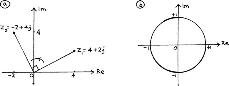
Figure 10.B.4
You should know now whether you got the right answer to the thinking point at the end of Section 10.A.(a) which asked you where the eight roots of z8 = 1 are.
They all lie on the unit circle with angles of π/4 between them.
Each of them has a modulus of 1 and there is one eighth of a full turn between each pair of roots so their arguments are 0, π/4, π/2, 3π/4, π, –π/4, –π/2 and –3π/4.
If you haven’t yet made your own drawing of these, draw them in now on the unit circle shown above in Figure 10.B.4(b) in a different colour to make them show up. Think how each of them will turn as it is multiplied by itself.
(1) If z1 = 3 + 2j, z2 = –2 + j and z3 = –3 – 5j find the following.
(a) 3z1
(b) 2z1 + 3z2
(c) 2z1 + z2 + z3
(d) 3z2 – 4z3
(2) (a) If w = z2 find w for the following values of z:
In each case, also find |z| and |w| and show w on an Argand diagram.
(b) If z = x + jy and w = u + jv, find |z|, |w|, u and v each in terms of x and y. If x and y are whole numbers, which of |z|, |w|, u and v must also be whole numbers?
(c) Each of the Argand diagrams from (a) will show you a right-angled triangle with sides whose lengths are whole numbers since, in each case, |w|, u and v are all whole numbers.
Sets of whole numbers which give the sides of right-angled triangles are called Pythagorean triples because they fit Pythagoras’ Theorem.
Two examples are 3, 4, 5 and 5, 12, 13 because 52 = 42 + 32 and 132 = 122 + 52.
It is possible to get some very strange shapes of triangle with sides given by Pythagorean triples.
Try finding w = (12 + 5j)2. Then find |w| and draw a sketch to show w on an Argand diagram.
Now use your result for w to find W = w2 = (12 + 5j)4. Find |W| and then show W on a new Argand diagram.
You could also try finding some new triangles like this for yourself. You can check if your working is correct by seeing if the lengths of the sides do fit Pythagoras’ Theorem.
(3) Check that the pairs of roots which you found for the four equations in Exercise 10.A.1 do fit the equations by substituting them back in. Then find the sum and the product for each of these pairs of roots and check that they do come to ‘–b/a’ and ‘c/a’ respectively in each case.
(4) One of the roots of the equation z3 = 1 is z = 1.
(a) Draw a little sketch showing all three roots of this equation.
(b) Find these three roots giving them both in mod/arg form and in a + bj form.
(c) These three roots are known as 1, ω and ω2, as we move round anticlockwise. Check that ω × ω gives ω2 and that ω2 × ω2 gives ω.

Can you work out where the four roots of z4 = –1 will be, drawing them on a little sketch and giving each of them both in mod/arg form and in a + bj form?
We can get the rules for this by thinking of dividing as a rearranged multiplying.
Just as with ordinary numbers, we can say (z1/z2) z2 = z1 so, from the rules for multiplying, we get the following pair of results.

To divide two complex numbers we divide their moduli and subtract their arguments.

Notice that, just as with ordinary numbers, the order matters here, unlike when we multiply. z1/z2 is not the same as z2/z1, so you must be careful when you work out the new modulus and argument.
As an example of using these rules, we’ll find (1 + j) ÷ (1 – j). I have shown these two complex numbers on the Argand diagram in Figure 10.B.5.
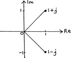
Figure 10.B.5
Using this, we can easily write the two complex numbers involved in this division in mod/arg form, that is, in the form z = [r, θ] where |z| = r and arg z = θ.
We have

In Section 10.A.(b) we found that the roots of the equation z2 – 8z + 25 = 0 are z1 = 4 + 3j and z2 = 4 – 3j. We saw in the Argand diagram of Figure 10.A.3 that they formed a symmetrical pair either side of the real axis.
Pairs of numbers which can be written in the form a + bj and a – bj are called complex conjugates.
If z = a + bj then its conjugate of a – bj is written as  .
.
The conjugate of a – bj is a + bj.
‘Conjugates’ means a sort of married couple – in fact the word stems from this original meaning.
You will see that since  and
and  it must be true that

Also,

because

You can also see that this must be so from the way in which they lie on the Argand diagram.  is the reflection of z in the real axis, so it must be the same length.
I have shown five complex numbers in Figure 10.B.6. Draw in their conjugates for yourself, labelling each one so that you can check if you have put them in the right places.
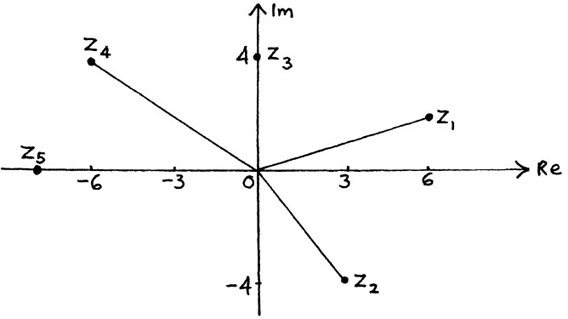
Figure 10.B.6
Complex conjugates are important in many areas. One of their uses is in simplifying fractions which have complex numbers underneath. Suppose we have the fraction

There is a very neat way of simplifying fractions like this, in which we convert the bottom of the fraction (its denominator) into a real number.
Can you see how we can do this? (We have already used this method for simplifying fractions with other square roots underneath in Section 1.F.(d). The only difference here is that now we are dealing with j, the special square root of –1.)

The trick is to multiply the bottom of the fraction by its conjugate. (Of course, in this case we must also multiply the top of the fraction by the same thing to keep its whole value unchanged.) This gives us

This is now in the very much more convenient form of the single complex number  . What we have done here is, in effect, a division.
We have found that (3 + j) ÷ (5 – 2j) = .
.
Try simplifying these yourself.
(5)  (Multiply out bottom first.)
(6)  (simplify each separate fraction first, and then add.)
Because of their structure, complex numbers have a special property which is of enormous importance.
Two complex numbers are equal if and only if each of their real and imaginary parts is separately equal.
We can show that this is true in the following way.
Let z1 = a + bj and z2 = c + dj. Then, if a = c and b = d, it is certainly true that z1 = z2.
Now we have to show that if z1 = z2 then a = c and b = d.
We can see that this must be true geometrically because complex numbers have direction as well as length, and therefore the only way that two of them can be equal, and so lie exactly on top of each other, is if their real and imaginary parts are separately equal.
We can also see this rather nicely in the following way, using algebra.
If z1 = z2 then a + bj = c + dj so
a – c = dj – bj = j(d – b).
Squaring both sides of this equation gives
(a – c)2 = j2 (d – b)2
so
(a – c)2 = – (d – b)2.
Therefore
(a – c)2 + (d – b)2 = 0.
But remember that a, b, c, and d are all real numbers. Because of this, we can say that (a –c)2 ≥ 0 and (d – b)2 ≥ 0.
Therefore, the only way for it to be possible that (a – c)2 + (d – b)2 = 0 is that each of (a – c) and (d – b) are equal to zero. Therefore a = c and d = b.
This property of complex numbers is of huge importance in their application to physical situations, because it means that any equation involving complex numbers is actually made up of two separate equations. We are, in a sense, getting two for the price of one.
EXAMPLE (1)
To see an example of this in action, we will solve the equation z2 = 5 + 12j.
Let z = a + bj. (We know the solution must be complex because its square is a complex number.)
We have (a + bj)2 = 5 + 12j so
a2 – b2 + 2abj = 5 + 12j.
This can only be true if both the real parts and the imaginary parts are separately equal.
Equating the real parts gives

Equating the imaginary parts gives

From (2) we have a = 12/2b = 6/b. Substituting this in equation (1) gives
 so 36 – b4 = 5b2 so b4 + 5b2 – 36 = 0.
This is much easier to solve than it looks at first, being one of those quadratic equations which are masquerading as something much nastier which we met in Example (4) in Section 2.E.(d). Factorising this equation gives (b2 – 4)(b2 + 9) = 0, (or you could put b2 = y, say, and then use the formula). This gives us b2 = 4 or b2 = –9.
Because b is a real number, we discard b2 = –9 as it will only give us imaginary solutions. This leaves us with the two solutions of b = +2 or b = –2.
The corresponding answers for a are a = 6/2 = 3 or a = 6/–2 = –3.
So the two solutions of the equation z2 = 5 + 12j are z1 = 3 + 2j and z2 = –3 – 2j. Check for yourself that they really work!
I show these two solutions in Figure 10.C.1(a).

Figure 10.C.1
Geometrically, we can see straight away that z1 is a solution of z2 = 5 + 12j. This is because |z2| = 13 and  , and also
arg  and
and  so arg
  .
.
(Check this numerically on your calculator.)
We know from the rules for complex multiplication given in Section 10.B.(b) that |z1| =  We also know that 2 arg z1 = 2 arg z2 = arg(z2).
In Figure 10.B.1.(b), you can see how these angles actually work. Doubling both arg z1 and arg z2 brings you round to the direction of z2. (Since arg z2 is negative, doubling it will mean that you are moving in a clockwise direction about the origin.)
The two square roots of a complex number will always be in the form ±(x + jy), so together they will always make a straight line on their Argand diagram.
We shall need to be able to find these square roots when we solve quadratic equations with complex coefficients in Section 10.D.(b).
(1) Find the square roots of each of the following complex numbers in a + bj form and show each of these pairs of roots on an Argand diagram.
(a) 3 + 4j
(b) 15 + 8j
(c) 5 – 12j
(2) Find the modulus and argument of each of the given complex numbers and sketch each of them on its own Argand diagram. Then use this to help you to find both of the square roots of each of the given numbers, showing them also on the Argand diagrams, and giving your answers in mod/arg form, that is, in the form z = [r, θ] where r = |z| and θ = arg z.
(a) 4j
At last we are able to solve the mystery of the resemblance between the trigonometrical functions cos t and sin t and the hyperbolic functions cosh t and sinh t.
To do this, we will need to use the series which we found in Section 8.G. I list below the ones which we shall need.


We know that et = cosh t + sinh t.
At the end of Section 8.G, we were left with the feeling that it should also be possible to link et, cos t and sin t together, but we couldn’t quite do it then. Now we have the extra possibilities given by complex numbers.
What happens if we put t =jθ in series (1)? We shall get

Now answer these questions yourself.
(1) Pick out the real parts in series (6) above to give a new series. What do you get?
(2) Make a new series with just the imaginary parts of the series above. Can you see what doing this will give you?
(3) What linking relationship have you now found?

The real parts of series (6) give the series for cos θ.
The imaginary parts of series (6) give the series for sin θ, so if we include the js too we have the series for j sin θ.
(Note: we are assuming here that it is all right to play around with these series in this way. In these particular cases, mathematicians have shown that it is all right but this is by no means a general rule. Infinite series have to be treated with great caution, as we saw for ourselves in Section 6.F.)
Putting together what we now have, we finally get our link, which is
ejθ = cos θ + j sin θ.
This is an amazing and beautiful result, and is due to the Swiss mathematician Euler after whom e is named.
Since z = ejθ = cos θ + j sin θ we can see from Figure 10.C.2(a) that z must lie on a circle whose centre is at the origin and whose radius is one unit. This circle is known as the unit circle about the origin.
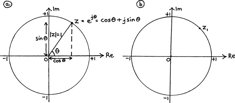
Figure 10.C.2
For any value of θ, the point representing z will be somewhere on this unit circle. Everywhere on this circle, |z| = 1 and arg z = θ.
To get the feel of what is happening, we’ll look at some particular possibilities for z as θ varies.
As a first example, if θ1 = π/4, we get the point z1 = cos(π/4) + j sin(π/4) =  . I have marked z1 on Figure 10.C.2(b).
What points do you get if you take (a) θ2 = 0 (b) θ3 = π (c) θ4 = π/2 (d) θ5 = –π/2 (e) θ6 = 2π/3? Mark each of the corresponding z values on Figure 10.C.2(b).
You should have the following points.
(a) z2 = e0 = 1, (b) z3 = ejπ = –1 because ejπ = cos π +jsin π.
The result ejπ = –1 is also due to Euler and is known as Euler’s Formula. It links three extraordinary numbers, e,π and j, to give the simple answer of –1.
Similarly; (c) z4 = ejπ/2 = j, (d) z5 = e–jπ/2 = –j, and (e) z6 = e2jπ/3 = cos 2π/3 +j sin 2π/3 = –1/2 +
As θ increases, z = ejθ is turning anticlockwise round the unit circle.
We know that ejθ = cos θ + j sin θ. If we put –θ instead of θ, we will get
e–jθ = cos (– θ) + j sin (– θ).
From Section 5.A.(c) we know that cos(–θ) = cos θ and sin(–θ) = –sin θ using the turn of P on its unit circle. This gives us
e–jθ = cos (– θ) – j sin (θ).
What will we get if we plot z = e–jθ on an Argand diagram?
If we start with θ1 = π/4 as before, and let  , using the * to distinguish it from the previous z1, we shall have
I have shown the turn to θ1 in Figure 10.C.3(a), and the position of  in Figure 10.C.3(b).
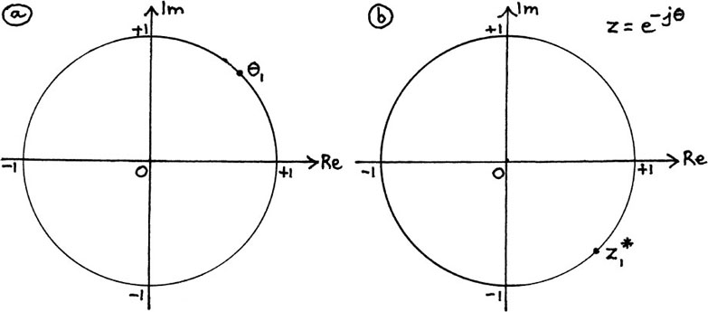
Figure 10.C.3
Now, using the same values of θ which you used in Section 10.C.(c), try finding the corresponding values for z* yourself. Mark each of your angles on Figure 10.C.3(a) and each of your values for z* on Figure 10.C.3(b).

You should have  and
and  .
.
As θ increases, z = e–jθ moves clockwise round the unit circle about the origin. This means that each z* is the reflection of its corresponding z in the real axis, so each z* =  for that particular z.
If z = ejθ then z = e–jθ.  so (ejθ)(e–jθ) = 1.
This exactly slots with the result given by multiplying z1 = ejθ and z2 = e–jθ and using the first rule of powers.
If z1 = ejθ and z2 = e–jθ then
z1 z2 = ejθ e–jθ = e(jθ – jθ) = e0 = 1.
We now have the following results:
ejθ = cos θ + j sin θ,
e–jθ = cos θ – j sin θ.
From this,
|
ejθ + e–jθ = 2 cos θ giving cos θ = |
and |
ejθ – e–jθ = 2j sin θ giving j sin θ = |
If we compare these results with cosh x =  and sinh
  and put x = jθ, we see that
cosh (jθ) = cos θ
and
sinh (jθ) = j sin θ.
The similar behaviour of the sin/cos and sinh/cosh pairs is no longer mysterious. These functions are all intimately linked together and these links explain the differences between the rules for trigonometric and hyperbolic functions. Every time we square a sin or sinh as part of our working, we get the cross-over from the imaginary to the real from putting j2 = –1. This is the reason for Osborn’s Rule which says that the formulas for the trigonometrical and the hyperbolic functions are the same except that we must change the sign whenever the working involves multiplying two sins or two sinhs together. (We met this rule in Section 8.D.(d).)
Since it was the series expansions which showed us the links between the pairs of cos and sin, and cosh and sinh, we can begin to see that it might be rather good to actually define these functions by using these series. This may seem alarmingly peculiar when you first meet it – after all, it is a very long way away from those original right-angled triangles. However, it does have many advantages, not least of which is that it is then possible to define what we mean by ez, sin z, cos z, sinh z and cosh z when z is complex. It is also possible to show that, if we do define sin and cos by means of series expansions, all the familiar properties are true if we consider only the cases for which z is real.
We know from Section 10.C.(b) that ejθ = cos θ + j sin θ.
If we put nθ instead of θ, we get ejnθ = cos nθ + j sin nθ.
But it can be shown that we can say ejnθ = (ejθ)n = (cos θ + j sin θ)n.
This gives us the following result which is known by the name of the French mathematician Abraham De Moivre.
De Moivre’s Theorem
(cos θ + j sin θ)n = (cos nθ + j sin nθ)
Here is one example of how we can use this.
Putting n = 2 gives us
(cos θ + j sin θ)2 = cos 2θ + j sin 2θ
so cos2 θ – sin2 θ + 2j sin θ cos θ = cos 2θ + j sin 2θ.
Now we use the fact that this equation is really two equations – we have two for the price of one, as we saw in Section 10.C.(a).
Equating the real parts gives us
cos 2θ = cos2 θ – sin2 θ
Equating the imaginary parts gives us
sin 2θ = 2 sin θ cos θ.
We have been able to show both the double angle rules from Section 5.D.(d) very simply. Notice the neat way in which using complex numbers gives us both rules from the same piece of working!
De Moivre’s Theorem makes it possible to find rules for multiple angles with a fraction of the work that would have been necessary up to now. As an example of this, I will show you how to write cos 5θ in terms of cos θ and sin 5θ in terms of sin θ, two results which examiners seem to be rather fond of.
Since we want rules for cos 5θ and sin 5θ, we put n = 5 in De Moivre’s Theorem. This gives us
(cos θ + j sin θ)5 = (cos 5θ + j sin 5θ).
To multiply out the left-hand side, we shall have to use a binomial expansion and this means that we shall need to know the right binomial coefficients to use.

Don’t leave these coefficients out!
Since n = 5, and 5 is quite a small number, much the easiest way to find the binomial coefficients is to use Pascal’s Triangle. We wrote this down in Section 7.A.(a).
The line of coefficients given by the triangle when n = 5 is
1 5 10 10 5 1
Because we shall be using Pascal’s Triangle a lot in this chapter, here is a brief reminder of how it works. Each new line is made from adding the two numbers nearest in the line above, unless it is at the end of the line when the single number closest to it is used. So, for example, if n = 6, the next line of the triangle would be
1 6 15 20 15 6 1
Remember that the triangle starts with 1 1 when n = 1.
Putting in the coefficients in our example, we have

I have written this working out in detail because mistakes often creep in here. In particular, notice that it is the whole of (j sin θ) which is being raised to the different powers.
Now we replace j2 by –1, j3 by –j etc. and tidy up generally.
Doing this gives us a right-hand side of
cos5 θ + 5j cos4 θ sin θ – 10 cos3 θ sin2 θ – 10j cos2 θ sin3 θ + 5 cos θ sin4 θ + j sin5 θ.
We also know from De Moivre’s Theorem that (cos θ + j sin θ)5 = cos 5θ + j sin 5θ.
Now we equate the real and imaginary parts of this equation, so getting double worth from our labours so far.
Equating the real parts gives us

and equating the imaginary parts gives us

Finally, if we want the RHS of equation (1) to be entirely in terms of cos θ and the RHS of equation (2) to be entirely in terms of sin θ, a proviso which examiners frequently make, what should we use?

We use the identity sin2 θ + cos2 θ = 1 to do the necessary adjustments. You may be wondering how this identity is going to help us with sin4 θ. Can you see how we can use it?

We can say that

This gives us


Now do the very similar process for yourself of equating the imaginary parts to show that

Try the following questions yourself.
(1) Show, using De Moivre’s Theorem, that
(a) cos 3θ = 4 cos3 θ – 3 cos θ and
(b) sin 3θ = 3 sin θ – 4 sin3 θ.
(2) Show that cos 7θ = 64 cos7 θ – 112 cos5 θ + 56 cos3 θ – 7 cos θ.
There is a rather similar problem (also popular with examiners) which we can now solve. This is basically a question of going back the other way.
How, for example, could we write cos7 θ in terms of cosines of multiples of θ?
To do this, we use the results of Section 10.C.(e) that
cos θ =  and
and  .
.
If we replace θ by nθ we get
cos nθ =  and j sin n θ =
  .
.
To save some writing, it is handy to let ejθ = z at this point, so that
enjθ = (ejθ)n = zn and e–jθ = 
We can then rewrite the above pair of results as follows:
If ejθ = z, then cos θ = and j sin θ =
  .
.
Also, cos nθ =  and j sin nθ =
 .
.
So how will we now set about writing cos7 θ in terms of cosines of multiples of θ? We can say
cos7 θ= .
.
Next, we use Pascal’s Triangle to get the binomial coefficients for the expansion of (z + 1/z)7. The line for n = 7 comes immediately from the line for n = 6 which we wrote down in the previous section. This was
1 6 15 20 15 6 1
So, when n = 7 we get
7 21 35 35 21 7 1
Using these coefficients gives us

 .
.
Now all that remains to be done is to use cos nθ = here. This gives us
 .
.
If you want sin7 θ in terms of multiples of sin θ, you just start with
 ,
,
and then work in a very similar way. You will find that the js will all cancel out.
You can also get slightly quirky extra results by differentiating a previous result.
For example, if we differentiate the expression which we have just found for cos7 θ with respect to θ, we get

so  .
.
(Examiners rather like this one, too.)
(1) Show that cos5 θ =  .
.
(2) By rewriting (j sin θ)5 in a different form, show that
 .
.
We can now see that the method for solving differential equations described in Section 9.C.(c) and questions (9) and (10) of Exercise 8.C.4 will also work for the equation d2x/dt2 = –x. (Newton’s dot notation is quite often used for this kind of equation. We write d2x/dt2 as  and dx/dt as
  . The differential equation then becomes
  = –x.)
We will find the solution for the particular case when we also know that x = 3 and dx/dt = 4 when t = 0. We have

and we try putting x = ekt. This gives us
 and
and 
If x = ekt is a solution of the given equation then we must have k2 ekt = –ekt or (k2 + 1) ekt = 0.
Since ekt is never equal to zero, we would have to have k2 = – 1 giving us k =j or k = –j.
Making the solution as general as possible gives us x =Aejt + Be–jt where A and B are constants.
Now we use Sections 10.C.(b) and (d) to say that
ejt = cos t + j sin t and e–jt = cos t –j sin t.
x = A (cos t + j sin t) + B (cos t – j sin t)
so x = (A + B) cos t + (A – B) j sin t.
If we let C = A + B and D = j (A – B), we have
x = C cos t + D sin t.
We are told that x = 3 when t = 0 so 3 = C.
Also, we know that dx/dt = 4 when t = 0.
Now,

This gives us the solution
x = 3 cos t + 4 sin t.
Examples (a), (c) and (d) in Section 9.C.(c) also all give solutions for x from the differential equation d2x/dt2 = –x. Each of these solutions is different because the values of x and dx/dt when t = 0 are different in each case.
I showed in Section 5.D.(f) that 3 cos t + 4 sin t can also be written as 5 sin (t + α) with  . You can see on Figure 5.D.3(a) how x changes with t.
This solution fits the general solution of an equation like this of x =A sin (ωt + ε) if we put A = 5, ω = 1 and  .
.
Now try solving the equation d2x/dt2 = –9x for yourself, given that we also know that x = 0 and dx/dt = 6 when t = 0.

This time, putting x = ekt gives us k2 + 9 = 0 so k = ±3j.
We now have the solution x = Ae3jt + Be–3jt.
Using

gives us

with C = A + B and D = j(A – B)
Also, x = 0 when t = 0 so 0 = C, and dx/dt = 3D cos 3t = 6 when t = 0 so D = 2.
This gives us the solution that x = 2 sin 3t. I showed what this particular x looks like in the first example at the end of Section 5.C.(b).
Comparing this solution with x = A sin (ωt + ε), we have A = 2, ω = 3 and ε = 0.
It is also possible to write the general SHM solution in the form x = A cos (ωt + ε). In this particular case, this would give us x = 2 cos (3t – π/2).
In Section 5.D.(g) we said that the combined effect of particular components in electric circuits, such as inductors, capacitors or resistors, can have the effect of making the current and voltage be out of phase with each other if there is an alternating electromotive force (e.m.f.). This phase difference will continue to be present even when the circuit has settled down after being switched on. (Initially there will also be transient responses, but these will die away leaving the circuit in a steady state.)
Suppose that the current in a single branch of a circuit network is given by I =  cos t – sin t and that the frequency is constant throughout the circuit.
At a junction, we know from Kirchhoff’s junction rule that what goes in must come out, or that the net current flowing into a junction must be equal to the net current flowing out of it. We are supposing that the other currents involved at this junction have the same frequency, but they could certainly have different amplitudes and phase constants. Therefore we would be faced with having to combine a string of terms like 2 cos (t + π/6), 3 cos (t – π/4) etc.
Adding these in the form of trig functions is unpleasantly complicated, but we can use the properties of complex numbers to make things much simpler.
Here’s how it would work in the case above.
From Section 10.C.(b), we know that ejθ = cos θ + j sin θ.
We have also seen there that, as θ increases, ejθ moves round the unit circle.
If we call the variable t instead of θ, and let t represent time, then z = ejt will have moved right round the unit circle once in 2π seconds.
How can we now use this to help us describe the particular current which we started with, I =  cos t – sin t?
Using the methods of Section 5.D.(g) we can rewrite  cos t – sin t in the form 2 cos (t + π/6). (This is, in fact, the answer to the first question of Exercise 5.D.1 at the end of that section.)
As we saw there, we can then use the motion of P on its circle to help us to see how the wave function of the current behaves. I show this again below in Figure 10.C.4.
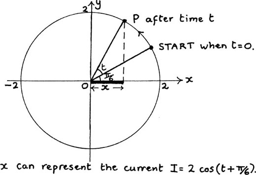
Figure 10.C.4
Now here is the step which links all the work which we were doing there with our present work on complex numbers, and which makes it possible for us to avoid a lot of tedious trig.
We can think of the current I = 2 cos (t + π/6) as being the real part of the complex number 2ej(t + π/6), or 2 exp[j(t + π/6)] as this is sometimes written to avoid cramped-up complicated powers.
We can also use the first rule of powers to say that
2 exp[j(t + π/6)] = 2 exp(jt) exp(jπ/6) or (2ejπ/6)(ejt).
(We know from the rule for multiplying two complex numbers that we must multiply their moduli and add their arguments.)
Now, 2ejπ/6 has a modulus of 2 (the radius of the circle), and an argument of π/6. It tells us the starting position of P and is called a phasor.
ejt has a modulus of 1 and an argument of t, and this argument tells us how far P has turned after a time of t seconds.
Multiplying the two together has the effect of using the ejt to drive P round the circle of radius two units. P starts from 2ejπ/6, and one full cycle takes 2π seconds.
One benefit of this is that, if we have all the currents at a junction represented by the real parts of complex numbers, we will be able to add these currents by adding the complex numbers. We know that the real parts will remain separate from the imaginary parts so, at any stage of the working, the real part will still represent current. There are other advantages too, which you will discover if you are studying the theory of what is happening in these circuits as part of your other courses.
If the currents are given as sin functions, it is equally possible to represent them by the imaginary parts of complex numbers. The only difference would be that they would be being represented on the vertical or imaginary axis instead of the horizontal or real axis.
Also, everything would work equally well with a different common frequency for a circuit. So, for example, if we had started with the particular current of I = 4 cos (3t + π/8), then we would use the real part of the complex number 4 exp[j (3t + π/8)] to represent this. The starting point of P would then be represented by the complex number 4ejπ/8, and the e3jt would then drive P round the circle as time passes. A full cycle would take 2π/3 seconds. I show this in Figure 10.C.5 below.
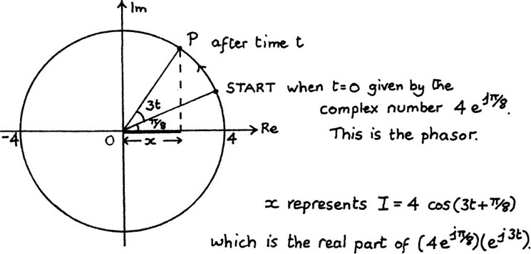
Figure 10.C.5
We have already found solutions to some particular examples of this kind of equation, such as z4 = 1 at the beginning of the chapter, and z3 = 1 in question (4) of Exercise 10.B.2. We did this by thinking how the turns should go to make the answers fit in with the rules for multiplying complex numbers.
In this section, we look for some general rules which will help us to solve any equation of this kind. We do this by using the relationship ejθ = cos θ +j sin θ which makes it possible for us to work out the answers for the n roots of the equation zn = a + bj in a very simple way. I shall use the thinking point from Exercise 10.B.2 at the end of Section 10.B.(c) to explain how this works. I asked you there if you could find the four roots of z4 = –1, so you will also be able to see now if your answers were right.
We start by noticing that |z4| = 1, because z4 = –1.
We also know that arg(z4) = π.
I show a sketch of z4 marked on the the unit circle in Figure 10.D.1(a).
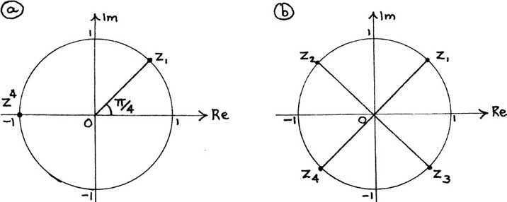
Figure 10.D.1
Geometrically, we can see that z1 is a root since |z1| = 1 and  . The other three roots must also all have a modulus of 1 since, when multiplied by themselves, they give an answer with a modulus of 1. Because of this, all the roots will lie on the unit circle. They will be given by successive quarter turns from z1, since four times any quarter turn makes a full turn. I have shown the four roots on Figure 10.D.1(b).
If we take z2, for example, we will have arg(z2) = π/4 + π/2 giving arg  using the rule for multiplying complex numbers from Section 10.B.(b). The extra full turn makes no difference to the point where we finish up, so
Now we see how all this fits in with using ejθ = cos θ + j sin θ.
We have
z4 = –1 = cos (π) + j sin (π) = ejπ
so z1 = (ejπ)1/4 = ejπ/4 = cos(π/4) +j sin (π/4).
We can get all the roots by writing the arg of z4 so that it includes the possibility of any whole number of extra full turns.
If we say arg(z4) = π + 2kπ, where k is any whole number, then

This power of e is rather cramped and difficult to read. Often such powers are written using exp instead of e so, for example, ejθ would be written as exp(jθ). Here we would have

Putting k = 0, 1, –1, and –2 gives the four distinct roots of exp(jπ/4), exp[j(3π/4)], exp[j(–π/4)], and exp[j(–3π/4)]. These are the four roots z1 z2, z3 and z4 which I have shown in Figure 10.D.1(b) above. There is one quarter of a full turn between each root and the next one, and any other value of k will give you one of the roots which you already have.
In exactly the same way, we can make a general rule for solving any equation of the form zn = a + bj.
Let zn = w, so |zn| = |w| and arg(zn) = arg w = θ say.
Then, just as we did in the previous example, we can say that arg zn = θ + 2kπ where k is any integer (that is, whole number), since adding any number of full turns leaves the argument unchanged.
So now we have
w = a + bj = |w| (cosθ + j sinθ) = |w| ejθ = |w| exp[j(θ + 2kπ)]
Therefore
z = w1/n = (|w| exp[j(θ + 2kπ)]1/n = |w|1/n exp  .
.
We summarise this result as follows:
A general rule for finding roots
If zn = w then z = |w|1/n exp 
where the n distinct roots are given by the n different integer values of k which make the arguments lie in the range –π < arg z ≤ π.

You should always draw a sketch of the roots on an Argand diagram so that you choose the right values for k.
EXAMPLE (1)
We will now find the eight distinct roots of z8 = 8 +  using the above result.
I let z8 = w, and start by drawing the sketch of w shown in Figure 10.D.2(a). We have

and

Using the symmetry of the eight roots, I now draw the sketch of where they will be in Figure 10.D.2(b). I am using arg 
Since we can add any number of full turns to arg w without altering it, we can say arg w = 2kπ + π/3 where k is any whole number.
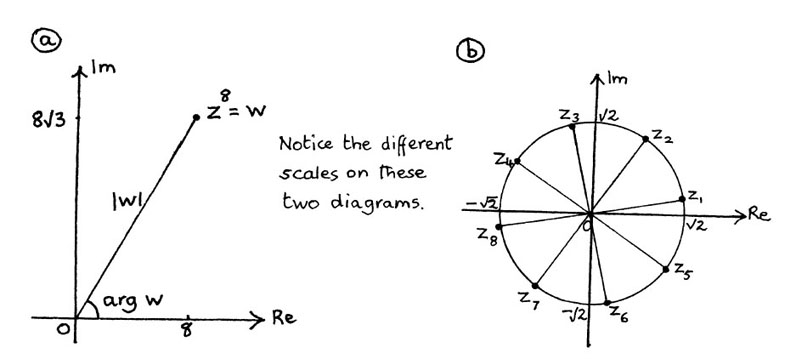
Figure 10.D.2
Therefore
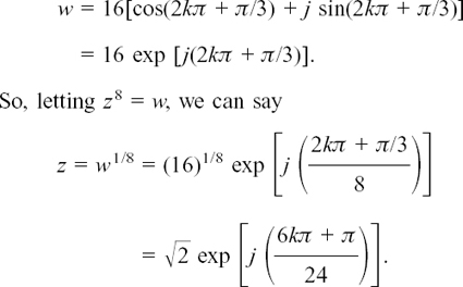
From the sketch, we can see that we should put k = 0, 1, 2, 3, –1, –2, –3 and –4.
Equally, you could find the solutions to z8 = 8 +  by just using the geometry of your sketch.
You know that |z8| = 16 and arg z8 = π/3 so therefore z1 (the first root you come to when you turn anticlockwise from the positive real axis) is given by |z1| = 161/4 =  and arg
  .
.
All of the roots have this same modulus of  .
.
Also, each of the eight roots is one eighth of a full turn (that is, 2π/8 or π/4) from the next one. Therefore, by looking at the diagram, it is easy to see what the correct argument for each one should be.
If you want your answers in the a + bj form, you simply use the relation of ejθ = cosθ + j sin θ to do the conversion.
For example, if you want z3, all you need to do is to put k = 2. This gives

(Notice that these numbers look reasonable from the sketch.)
Try solving these equations yourself now. For each question, sketch the starting number and its roots on an Argand diagram.
(1) Find the cube roots of 27j.
(2) Find the four solutions of z4 = 1 + j.
(3) Find the three cube roots of  both in mod/arg form, and in a + bj form, giving a and b correct to 2 d.p.
(4) Find the fifth roots of –4 + 4j in exp form.
(5) Find the six distinct solutions of  in exp form.
(This is not as horrible as it looks. Think about what we have already found in this section before rushing into binomial expansions.)
Suppose you have an equation like z2 + (2 + j)z – (3 + j) = 0 to solve.
Students are sometimes alarmed by the presence of complex coefficients. There is no cause for concern, however. The usual quadratic equation formula can be used with an equation like this.
Here, we have a = 1, b = 2 + j and c = –(3 +j) so substituting in the formula gives

Check that you also get 15 + 8j when you tidy up under the square root sign.
Now we have to find the two square roots of 15 + 8j.
We use the method of Section 10.C.(a) to do this, so we let w2 = 15 + 8j where w = u + jv. (I have not used the letter z since it is already being used in this example.) We have

Equating the real parts gives

Equating the imaginary parts gives

Therefore

u is real so the only two possible solutions are u = +4 or –4 giving v = +1 or –1.
The square roots of 15 + 8j are ±(4 + j). (Notice that this method of solution automatically gives us the ± which is included in the quadratic equation formula, and that together these roots would make a straight line on an Argand diagram.)
Now, substituting them back in the quadratic equation formula, we find that the two possible solutions for z are given by

Notice that these two roots do not form a conjugate pair because the coefficients of the original equation were not all real, but they do fit the rules from Section 2.D.(e) that the sum of the roots is –b/a, and the product of the roots is c/a. (Check this for yourself.)
Try solving the following quadratic equations yourself. (You may find that your answers to Exercise 10.C.1 are helpful here.)
(1) z2 – (3 – 2j)z – (1 + 3j) = 0
(2) z2 + (3 – 4j)z – (22 + 6j) = 0
(3) z2 + (2 + j)z – (3 + j) = 0
(6) z2 – 2(1 + j)z + 5(1 – 2j) = 0
How we do this is very similar in many ways to what we did in Section 2.E.(a) in order to solve cubic and quartic equations with real roots. You might find it helpful to go back there before going on with this section.
The following two examples will show you these similarities, and also how we use the extra information if we are given one complex root.
EXAMPLE (1)
We will solve f(z) = z3 – 5z2 + 9z – 5 = 0.
We can easily find one root here. (Can you spot it?)

Putting z = 1 gives f(z) = 0 so z = 1 is a root, and this means that (z – 1) is a factor. Matching up what we know gives us

where p stands for the number which we don’t yet know.
Looking at the terms in z2, we get
–5z2 = –z2 + pz2 so p = –4.
(Check for yourself that this is right by looking at the terms with z.)
The other two roots of f(z) = 0 will come from solving z2 – 4z + 5 = 0. They are

The three roots of z3 – 5z2 + 9z – 5 = 0 are z = 1, and z = 2 ±j.
EXAMPLE (2)
Now we’ll solve z4 + az3 + bz2 – 5z – 26 = 0 given that z = 2 + 3j is one root of the equation, and a and b are real. We’ll also find the values of a and b since examiners often like being given this information.
Since the coefficients of this equation are all real numbers, any complex roots of it must come in conjugate pairs, because otherwise multiplying out the factors would give us stray unwanted j’s.
Therefore what else must be a root?

There must be a second root of z = 2 – 3j.
Now, in just the same way as we said in the last example that if z = 1 is a root of f(z) = z3 – 5z2 + 9z – 5 = 0 then (z – 1) is a factor of f(z), here we can say that both (z – (2 + 3j)) and (z – (2 – 3j)) are factors.
These look rather alarmingly complicated, but if we multiply them together we shall get something very much nicer. We shall have

The imaginary part has disappeared because the roots are conjugates, so making it possible for the original equation to have only real coefficients. Now we can say that

matching up the first and last terms in the second bracket, since we know that when we multiply the two brackets together they must give us z4 and –26. Again, p is standing for the number which we don’t yet know.
Just as in the first example, we can now match up the terms for the various powers of z, since the right-hand side is just another way of writing the left-hand side.
We have already matched the z4 and number terms.
Matching the terms in z, we get

Now we have

so we’ll match up the terms in z3 to find a, and in z2 to find b. Notice here that we have to get the arithmetic right first time; we can’t use these equations as checks because we need them to find new information.
Matching up the terms with z3 gives us
az3 = –4z3 – z3 so a = –5.
Matching up the terms in z2 gives us

(We have to be careful with this one because there are three ways in which we can make z2 on the right-hand side.)
We now have

To find the other two roots, we now just have to solve the equation z2 – z – 2 = 0. Now z2 – z – 2 = (z – 2)(z + 1) so the two solutions are z = 2 and z = –1. In this particular example, they have both turned out to be real.
It has been shown by mathematicians that every equation like the one that we started with here will have the same number of roots as the highest power of z, if we both allow complex roots, and count roots such as x = 1 from (x – 1)2 = 0 as a double root. (Here, the curve is just sitting on the x-axis instead of cutting it in two places.) Also, if all the coefficients of an equation are real numbers, then the roots must come in conjugate pairs. How does this apply to the two roots of z = 2 and z = –1 which we have just found?

Each of these is its own conjugate because they are real numbers.
Now we will try one together, before I give you an exercise on these.
Given that a and b are real, and that z = 2 +j is a root of the equation z4 + az3 – 9z2 + bz + 30 = 0, find the values of a and b and the other three roots.
(1) What else must be a root?

Since a and b are real, the conjugate of 2 + j which is 2 – j must also be a root.
(2) From these two roots, what two factors must you have?

We have the two factors
(z – (2 + j)) and (z – (2 – j)).
(3) When you multiply these two together, what single nice factor do you get?

You get
z2 – (2 + j)z – (2 – j)z + (2 + j)(2 – j) = z2 – 4z + 5.
(4) Use all this information to write z4 + az3 – 9z2 + bz + 30 as two factors multiplied together.

You should have
z4 + az3 – 9z2 + bz + 30 = (z2 – 4z + 5)(z2 + pz + 6)
where p is standing for the number which we still have to find.
(5) Now, match up the terms in z2 to find p.

You should have
– 9z2 = 5z2 + 6z2 – 4pz2 so p = 5.
(Notice the three ways of getting z2 on the RHS again!) We now have
z4 + az3 – 9z2 + bz + 30 = (z2 – 4z + 5)(z2 + 5z + 6).
(6) Now match up the terms in z3 and z to find a and b.

You should have
az3 = –4z3 + 5z3 so a = 1,
bz = –24z + 25z so b = 1 also.
(7) Finally, what are the other two roots of the given equation?

z2 + 5z + 6 = 0 if (z + 3)(z + 2) = 0
so the other two roots are z = – 3 and z = – 2.
It’s worth noticing that if you were only asked for the roots then you could have left out step (6) altogether. You don’t need to know the values of a and b to solve the equation.
It is also possible to answer the original question by substituting z = 2 + j in the original equation, since we know that it fits it. Then we would equate the real and imaginary parts to find a and b, and also find the first factor with z2 as we did above. Then you either use long division to find the other factor, or match up the terms as we did above. This method involves using binomial expansions to work out (2 +j)4 and (2 +j)3, always a fruitful source of arithmetical mistakes. I think that you will find that the method I have shown you is easier.
Now have a go at solving these equations yourself.
(1) Given that a and b are real numbers, and that z = 1 – 2j is a root of the equation z4 – 3z3 + az2 + bz – 30 = 0, find a and b and the other three roots.
(2) Given that a and b are real numbers, and that z = j is a root of the equation z4 + az3 + bz2 – 4z + 13 = 0, find the values of a and b and the other three roots.
(3) Given that a and b are real numbers, and that z = 1 – j is a root of the equation z4 + az3 + bz2 + 1 = 0, find a and b and the other three roots.
In Chapter 3, when we were working with functions, we often found that we had to restrict the choice of possible values for x in order to make the functions work as we wanted. One example of this is given by  . To make f(x) real, we have to have x ≤ 4. This means that we have to restrict the possible values of x to just one part of the number line which makes up the horizontal axis.
The same kind of thing can happen with applications of complex numbers. To make things work in the way that we want, we may often find that we have to restrict the possible values of z. Since z is made up of both an x and y component from its real and imaginary parts, this restriction may lead to the exclusion of any area or region of the complex plane because it may affect the possible values of both x and y. (The complex plane is the flat surface shown on an Argand diagram.)
Physical quantities which have both magnitude and direction, and which are acting in a flat surface, can often be represented very conveniently by complex numbers. Examples of such applications are two-dimensional problems involving lines of electric or magnetic force, or streamlines in fluid flow. If the physical quantities you are considering need three dimensions to describe them, complex numbers will no longer be any use. You would probably then use vectors, as I explain in the next chapter.
The following section is designed to give you more practice in using complex numbers and seeing how particular restrictions could be described.
If complex numbers are described by saying that they obey some rule, we can use this information to show the possible points in the complex plane where these numbers may lie.
Suppose we are told that |z| = 3.
This means that the distance of the point z from the origin is always 3 units, so therefore z can lie anywhere on the circle shown in the Argand diagram in Figure 10.E.1.
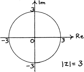
Figure 10.E.1
We could also write the equation of this circle using xs and ys as we did in Section 4.C.(d) by letting z = x + jy and using the relationship |z|  . Since |z| = 3, we then have x2 + y2 = 32 = 9 which is the equation of the circle with centre (0,0) and radius 3 units. All the possible positions of z lie on the path given by this circle. Such a path is sometimes called the locus of z.
There is a third way of describing this particular circle. We know from Section 10.C.(c) that z = ejθ gives the unit circle about the origin as θ varies. Therefore z = 3ejθ gives the unit circle enlarged by a factor of 3, and this is our circle.
EXAMPLE (2)
Suppose we are told that |z| ≤ 2.
We want the distance of z from the origin to be less than or equal to 2 units, so it must lie either on or inside the circle shown in Figure 10.E.2 below. This time the possible positions of z make a region in the plane, rather than a path given by a line as in Example (1). (You may find it helpful to use your own colour on these diagrams to highlight the different possible positions of z.)
This region can be described as either |z| ≤ 2 or as x2 + y2 ≤ 22 which is the same as x2 + y2 ≤ 4.
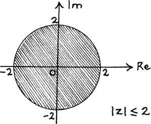
Figure 10.E.2
Suppose we are told that arg z = π/3.
The argument of these complex numbers is fixed but their modulus can take any value. This means that z can lie anywhere on the straight line shown below in Figure 10.E.3.
The arrow on the end of the line which represents the possible values of z shows that it can be extended indefinitely. Such a line is sometimes called a half-line because it can only be infinitely extended in one direction. Extending it in the opposite direction would include points for which arg z = –2π/3, and this doesn’t fit the given condition.
EXERCISE 10.E.1
Use separate Argand diagrams to show the possible positions for z for each of the following.
(1) |z| = 4
(2) |z| ≤ 1
(3) arg z = –π/6
(4) arg z = 0
(5) |z| > 2
(When the boundary of a region is not included, show it with a dashed line.)
Each of the examples which we have looked at so far has been related directly to the origin. What will happen to the path if the information that we are given concerns a complex number which has been shifted away from there?
EXAMPLE (1)
Suppose we are told that |z – 5| = 2. Where is the path which describes the possible positions of z now?
If we let z – 5 = w then we know that the path for w is the circle about the origin with a radius of 2 units. But what do we have to do to z to get w?

We have to subtract 5 from z which means that we are taking 5 away from the real part of z since 5 itself is real. Therefore we are shifting z by 5 units to the left to get w. So the circle giving the path for z must be 5 units to the right of the origin. I show both these circles on the pair of Argand diagrams in Figure 10.E.4.
We can check that the path of z is in the right place by putting z = 7. Then |7 – 5| is indeed equal to 2, and we see from the diagram that z = 7 is a point on the path of z. The equation of this circle in terms of x and y is given by (x – 5)2 + y2 = 22 or x2 – 10x + y2 + 21 = 0 because its centre is at (5, 0) and its radius is 2 units. (If you need help with this, you should go to Section 4.C.(d).)
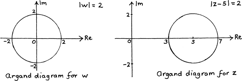
Figure 10.E.4
EXAMPLE (2)
What would the path of z be if we are told that |z – 3j| = 1?
Try drawing a sketch for yourself of where you think it would be.
Check your sketch by using z = 4j as a test point, and write down the equation of the path of z in terms of x and y.

If we put w = z – 3j then the path of w is the circle about the origin with a radius of one unit since |w| = 1.
To get w from z, we have to subtract 3 from the imaginary part of z.
Therefore the path of z is the circle whose radius is one unit and whose centre is at the point (0,3). That is, the centre of the circle is at the point which represents the complex number 3j. I show the w circle and the z circle in the pair of Argand diagrams in Figure 10.E.5.
The equation of this circle can also be written as x2 + (y – 3)2 = 12 or x2 + y2 –6y + 8 = 0.

Figure 10.E.5
The general case of |z – (a + bj) | = k.
We can now see what the path of possible points for z will be if we are told that |z – (a + bj) | = k, where a + bj is any given complex number and k is any given real number.
This is because if we put w = z – (a + bj) then the path of w is the circle about the origin with a radius of k units. To get to w from z, we have to subtract a units from the real part of z and b units from the imaginary part of z.
Therefore the path of z is the circle whose radius is k units and whose centre is at the point (a, b), that is, at the point which represents the complex number a + bj. If z = x + jy then the equation of this circle can be written as (x – a)2 + (y – b)2 = k2.
EXAMPLE (4)
Suppose we are told that arg (z + 1) = π/3.
This time, we want to find the path of z from knowing what its argument is after it has been shifted.
If we let z + 1 = w then we can immediately sketch the position of w on an Argand diagram. I have done this in Figure 10.E.6(a).
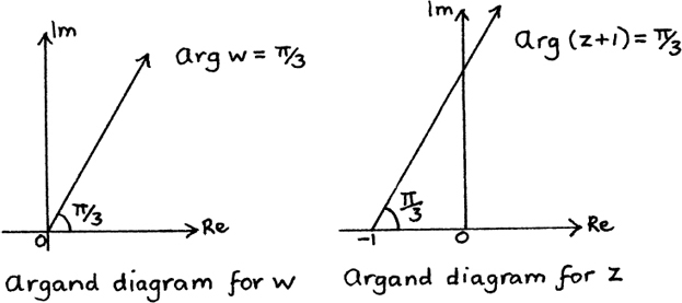
Figure 10.E.6
Since z has been shifted to the right by one unit to give w, we can now draw in the path of z on its Argand diagram. I show this in Figure 10.E.6(b).
Show the paths giving the possible positions of z from the information given in each of the following questions. (I have included one rogue question which is impossible. Which one is it?)
It is possible to use algebra to find where z must be in the complex plane if it has to fit certain conditions. If the geometry of what is happening gets more complicated then it is often easier to take this approach.
I will start by showing you how we could have used algebra to solve the first example that we looked at in Section 10.E.(b), so that you can see how we get the same answer.
We were told that |z – 5| = 2 and we had to find the path which z could take in order to fit this condition.
We start by putting z = x + jy which gives us |x + jy – 5| =2.
Next, we tidy up the x + jy – 5 to show the real and imaginary parts separately and clearly. Doing this gives us
|(x – 5) +jy| = 2.
Therefore we can say that
 (1)
(1)
using the rule that  from Section 10.A.(c).

Don’t be tempted to think this should be  Remember that the j is telling you that the y is measured vertically. We then use Pythagoras’ Theorem on the right-angled triangle shown in the sketch in Figure 10.E.7 to get |w| where w = (x – 5) + jy.
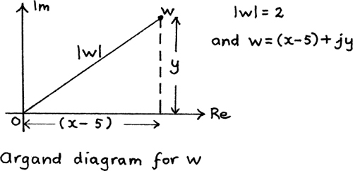
Figure 10.E.7
Squaring both sides of equation (1) above gives us (x – 5)2 +y2 = 22 = 4.
This is the equation of the circle with centre (5,0) and radius 2, which agrees exactly with what we obtained at the beginning of Section 10.E.(b) for the path of z by using the geometry of the diagram.
EXAMPLE (2)
My second example involves a more complicated situation where it is definitely easier to use algebra.
We will find where z can be in the complex plane if

From the rule for dividing complex numbers, we know that

so here we have

which means that

This gives us

It is possible to do this last step because we know that |z + j| is positive since it is a length. Therefore, multiplying both sides of the inequality by it does not change the ≤ sign to a ≥ sign. (If k is a positive number, and a ≤ b, then ka ≤ kb also.)
Next, we put z = x + jy and then carefully tidy up to show the real and imaginary parts separately and clearly.

Doing this is very important!
We get

Since both sides are positive, the inequality remains true in the same sense if we square them both. (If they weren’t both positive this would not necessarily be so. For example, –3 < 2 but (–3)2 > (2)2.)
Squaring both sides gives us


Don’t forget to square the 2!
Now we have

We then use the method of completing the squares to get the centre and radius of the boundary circle. (See Sections 2.D.(b) and 4.C.(d) if necessary.) It is easier to complete the squares here if we divide all through by 3 to get x2 and y2.
Doing this gives

so  or
or 
The boundary of the region where z can lie is the circle whose centre is  and whose radius is
  (If you have any trouble with this step, you should go back to Section 1.F.(c) for help.)
Since the form of the inequality tells us that the distance of the point representing z from the centre of this circle is greater than or equal to its radius, the region where z may lie is the circumference of the circle and everywhere outside it.
I show this in Figure 10.E.8. The centre of the circle is given by the complex number 
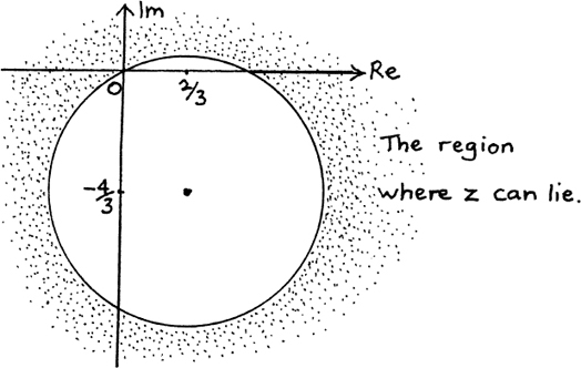
Figure 10.E.8
EXAMPLE (3) Find the region in the complex plane in which z can lie if

First, we put z = x + jy, giving us

Next, we tidy up the fraction

so that we can easily see what its imaginary part is.
We do this tidying up by multiplying its top and bottom by the conjugate of the bottom which gives

so 
Now we put

to see where z can lie. This gives us
–4x ≥ 2x2 + 2(y + 4)2.
(We can do the above multiplication because we know that x2 + (y + 4)2 is positive since x and y are both real.)
Dividing by 2 gives us

So 
This means that z can lie anywhere on or inside the circle whose centre is at the point – 1 – 4j and whose radius is one unit. Sketch this for yourself.
Now try these questions for yourself.
(1) Find the path on which z can lie if
(2) Find and sketch the regions where z can lie in the complex plane for each of the following given conditions.
(c) 2|z| ≤ |2z–j|
In the examples of Section 10.E.(b) we saw how we could write rules given for a variable number z so that they were in terms of a new variable number w instead. I shall finish Section 10.E by looking at an example where we are given a relationship between z and w which isn’t just a simple shift. We shall then use this to find out how making z obey a special rule will affect w.
We will start with the relationship

with w = u + jv and z = x + jy.
We’ll now answer some questions about how this relationship works.
(1) Can you see a value of z which we must exclude?

(1) We can’t have z = j since this would give us a zero on the bottom of the fraction.
(2) Each value of z will give a corresponding value of w and vice versa.
What will w be if (a) z = 1 +j, (b) z = 3 +j, (c) z = 3 – j?
Try answering this yourself, giving your answers in as simple a form as you can

(2) You should get
(a) w = 1 + 2j
(b) w = 
(c) w = 
Simplifying (c) by multiplying top and bottom by the conjugate 3 + 2j gives 
(3) What are the real and imaginary parts of w in terms of the real and imaginary parts of z?
Putting w = u + jv and z = x + jy gives

Now we simplify this fraction by multiplying its top and bottom by the complex conjugate of the bottom. Try doing this for yourself.

(3) You should have

(4) Now see if you can write down what u and v are in terms of x and y.

(4) Equating the real and imaginary parts from above should give you

(5) If we now make the special condition that the real and imaginary parts of w are equal, so that w lies on the straight line u = v, what path will z lie on?
If u = v it must be true that x2 + y2 – 1 = 2x since the bottoms of the fractions are the same.
This gives us x2 – 2x + y2 – 1 = 0 so (x – 1)2 + y2 = 2.
Therefore z lies on a circle whose centre is at (1,0) and whose radius is 

(5) The easiest way to show what is happening geometrically is to draw two separate Argand diagrams for each of w and z.
Doing this gives us Figure 10.E.9

Figure 10.E.9
The little circle on the imaginary axis at +1 in (b) is to show that z = j isn’t allowed.
(6) We will finish off this example by finding out how a few points will transfer from one Argand diagram to the other. (Notice that none of the points which we found in (1) will help us here as u and v are not equal for any of them.)
We will look first at how two points will move from (b) to (a).
What is w when (i) z1 = –j and (ii) z2 = 2 + j?

(6) (i) If z1 = –j then w1 = 0.
(ii) If z2 = 2 + j then

Mark these two pairs of points on the Argand diagrams. (You can see that z2 = 2 + j really is on the circle of (b) if you put x = 2 and y = 1 in its equation.)
Now we’ll go the other way. It will be easier to do the working out if we start by finding out how we can write z in terms of w. We have

so  so
so 
We only want points for which u = v.
What is z if (iii)  and (iv) w4 = –1 –j?

Tidying up by multiplying top and bottom by j + 1, we get

(iv) w4 = –1 – j gives 
Mark these two pairs of points on the two Argand diagrams of Figure 10.E.9. as well.
One important application of relationships like this is in the description of electric circuits by using complex numbers. Working as we have done above could make it possible to find out what happens to, say, the output impedance of a circuit from a given variation in the input impedance.
Try this example for yourself now.
If w = u + jv and z = x + jy and w and z are related by the equation

answer the following questions.
(1) What value of z must we exclude?
(2) What is w if (a) z = 2 and (b) z = 1 – j?
(3) Find the real and imaginary parts of w in terms of the real and imaginary parts of z.
(4) If the real and imaginary parts of w are equal, find the path on which z must lie.
(5) Show the paths of z and w on two separate Argand diagrams.
(6) Find w if
(b) z2 = 2 – j
Mark each of these pairs of points on your two Argand diagrams.
(7) If v = 0, so that w lies on the real axis, where must z lie?
(8) If u = –v what is the path on which z must lie?
(9) Sketch two diagrams showing the three paths of w from (4), (7) and (8) on the first diagram and the corresponding three paths of z from (4), (7) and (8) on the second diagram.
(10) The three paths of w cut each other at the origin.
The three corresponding paths of z cut each other at z = –j.
Compare the angles between the paths at these two points on your two sketches. What do you find?
