Digi-Key (http://www.digikey.com/) or Mouser Electronics (http://www.mouser.com/) I do most of my general component shopping at these sites. Mouser is often slightly cheaper, but Digi-Key offers the cheapest shipping options as of this writing.
Welcome to the appendices! This first appendix will introduce you to all the standard electronic components, the tools you need use them, and the skills it takes to harness their awesome powers.
It’s almost always cheaper to buy electrical components and tools online, but if you live near a shop serving electrical tinkerers or ham radio enthusiasts, go there first. These shops generally offer excellent deals and recommendations, especially on bigger investments, like a good multimeter or benchtop soldering iron station. Their stock often includes a mind-boggling array of awesome rarities salvaged from estate sales and auctions. As a bonus, these shops are invariably staffed by wise old folks with a bottomless reservoir of tips, tricks, and quick fixes. Sourcing supplies from your local ham shop is a great way to get an idiosyncratic education in shade-tree EECS, plus the occasional story about the early days of DARPA or off-color anecdote about World War II–era South Pacific remote listening posts.
Resistors, transistors, diodes, switches, and the like generally don’t vary a lot between manufacturers; as a rule, I buy the cheapest version of whatever fits the parameters.
Jacks are the one exception I make to this rule. Normal operation puts a great deal of strain on jacks, especially the springy metal tongue that presses against the plug’s tip. In a cheap jack, this tongue deforms over time, leading to a loose, noisy connection. Buy a high-quality jack, like those made by Switchcraft, and save yourself headaches down the road. Switchcraft models L11, L12A, L12B, and 112AX will be suitable for all of the projects in this book.
Sources for buying online:
Digi-Key (http://www.digikey.com/) or Mouser Electronics (http://www.mouser.com/) I do most of my general component shopping at these sites. Mouser is often slightly cheaper, but Digi-Key offers the cheapest shipping options as of this writing.
Jameco Electronics (http://www.jameco.com/) I’ve never ordered from Jameco, but it comes fondly recommended by friends and colleagues and has an easily navigable website.
Micro Center Computers & Electronics (http://www.microcenter.com/) This is a good choice if you find the above sites too daunting. The search function is more straightforward, and you can click the Site Map link to navigate to the Hobby Electronics section. Also consider All Electronics (http://www.allelectronics.com/).
Antique Electronic Supply (https://www.tubesandmore.com/) For musicrelated supplies and kits, including vintage parts and hard-to-find musicspecific components, try this site. It’s my preferred source for pickup winding wire; search for 42 AWG 750 to find reasonably priced small spools.
Small Bear Electronics (http://smallbearelec.com/) An excellent source for classic knobs, enclosures, stomp switches, and more. Small Bear also has some great DIY articles in its Deep Cave section (http://diy.smallbearelec.com/).
Finally, always keep an eye out for weirdo components that might inspire future projects. Check out American Science & Surplus (http://www.sciplus.com/) as well as garage sales, resale shops, and local freecycle groups.
Many components, especially capacitors and some resistors, have wattage and voltage ratings printed on them. All you need to know is that any 1/4- or 1/2-watt component is fine for these projects, as is anything rated more than 9 volts. Most will be 16 or 35 volts. You should always use components rated higher than the amount of voltage you plan on applying to them.
* WARNING: Because the batteries used in the projects in this book are small and supply relatively low currents, every project featured here is safe. Don’t try to rework any of these to run on more than a 9-volt battery, and please don’t use the information in this book as permission to start messing with wall current!
Resistors are electrical components that conduct current but impede its forward flow. Resistance is measured in ohms, abbreviated with the symbol:, with values usually in the hundreds or thousands.
Fixed resistors are little lozenges with wires sticking out of either end (see Figure A-1). They are labeled with three colored bands grouped as a set, then a space, and then a fourth band that’s almost always silver or gold.
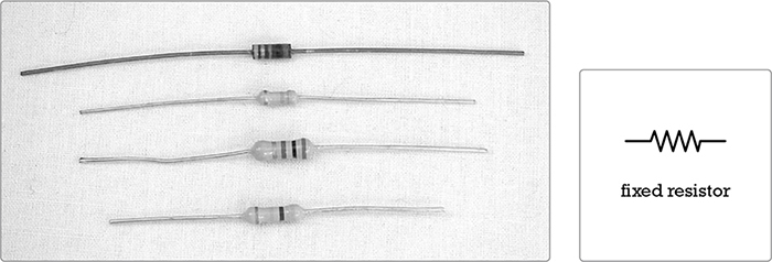
FIGURE A-1: Several fixed resistors and the resistor symbol (right) used in circuit diagrams
If you hold the resistor so that the three-band group is to the left, the first three colored bands give the resistor’s value, or its resistance in ohms, and the last band tells you its tolerance, or how close to that value it really is. Resistors are cheap, so you should always purchase those with a gold fourth band, which corresponds to a tolerance of ±5 percent. That tolerance means the resistor’s true value is no more than 5 percent above or below the labeled value; for example, if you use your multimeter to measure the actual resistance of a “100 ohm” resistor with a gold band, you’ll find that it measures somewhere between 95 ohms and 105 ohms. Silver is ±10 percent, meaning the resistor’s true value could deviate a lot more from the labeled value.
When you’re reading a resistor value, the first two bands provide the numerical value, and the third tells you how many 0s to tack onto the end, as shown in Table A-1.
For example, a resistor with brown-black-orange bands has a value of 1 (brown) and 0 (black) followed by three 0s (orange), and is thus 10,000 ohms, or 10k ohms. If you need to find a 470 ohm resistor in your bin, look for the one marked with a yellow band (4), a purple band (7), and a brown band (add one 0).
* NOTE: If this is confusing—and it usually is at first—google resistor value decoder. The Internet abounds with Java-based resistor decoders.
TABLE A-1: Resistor Value Decoder
Value |
|
Black |
0 |
Brown |
1 |
Red |
2 |
Orange |
3 |
Yellow |
4 |
Green |
5 |
Blue |
6 |
Violet |
7 |
Gray |
8 |
White |
9 |
The order of the colors in the chart is the same as the order of the colors in the rainbow (ROY G BV). In other words, the system has a built-in mnemonic: just remember “black-brown-ROY G BV-gray-white,” and you’ll remember the values from 0 through 9.
Variable resistors can be adjusted to offer different amounts of resistance—usually between 0 ohms and their marked value (see Figure A-2).
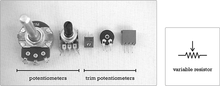
FIGURE A-2: Variable resistors: two potentiometers and three trim potentiometers (left) and the variable resistor symbol (right)
The larger variable resistors, which are usually accessible from the outside of the finished project’s enclosure, are meant to be adjusted often and are called potentiometers, or pots. Very small variable resistors that are meant to be adjusted only during the initial building stage are usually called trim pots, or trimmers, though they’re sometimes referred to as set-and-forget variable resistors. A variable resistor can have either an audio (also known as logarithmic) taper or a linear taper. Unless told otherwise, use a linear taper pot in most applications and an audio taper pot for volume controls.
The Gory Details: Audio Taper vs. Linear Taper
A strip of resistive material inside your pot connects lugs 1 and 3. Lug 2 connects to the wiper, a separate conductor that you move by turning the pot’s shaft. Current can flow from lug 2 to lug 1 or 3, but it has to pass through that conductive strip first. The resistance across lugs 1 and 3 matches the marked value of the pot, but the resistance between the middle lug and either outer lug depends on the position of the wiper: as you move the wiper, the resistance between either outer lug and the middle lug varies between 0 and the marked value of the pot. That resistive material running between lugs 1 and 3 is tapered so that it offers consistently varying resistance as the wiper moves from one end to the other. Most pots have a linear taper, so when the wiper is at its halfway point, the resistance is half the marked value of the pot; when it’s at its 3/4 point, the resistance is 75 percent; and so on.
This is great for most electrical signals, but lousy for controlling the apparent volume of audio sources because we perceive audio amplitude logarithmically: for a sound to seem twice as loud, it must be exponentially more powerful. To address this problem, some pots have a taper that approximates a logarithmic progression; these are said to have an audio taper or—less often—a logarithmic taper.
The pot’s value is usually printed on its face, with an A prefix for audio tapers and either a B or no prefix for linear tapers. In this book, a pot’s lugs are numbered from left to right when the pot is viewed from the front with the lugs on top, like a crown. This means they’re numbered from right to left when viewed from the back, which is the view you’ll often have when you’re soldering or troubleshooting (see Figure A-3).
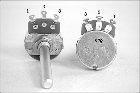
FIGURE A-3: Variable resistors, viewed from the front (left) and back (right), with lugs labeled
The Gory Details: Selecting the Right Photoresistor
Photoresistors are variable resistors that change resistance according to the level of light that falls on them. Most commonly available photoresistors offer near-zero resistance when exposed to bright light and then shoot up to around 1.2M ohms when plunged into full darkness. This allows for all sorts of neat effects—machines that “magically” start as you approach, synths that change their tune as the sun sets, automatic nightlights—making them a favorite of DIYers. But despite their hobby popularity, photoresistors are still mildly infuriating from an engineering standpoint: every photoresistor is unique and often a touch finicky. They’re wickedly inconsistent from manufacturer to manufacturer—even batch to batch—and relatively slow to change states (especially by modern microprocessor standards, where lag times are measured in milliseconds). Most vexing for modern applications, a photoresistor doesn’t jump from 0 to 1M ohms, no matter how quickly the nightlight seems to shut off when you turn on the lights. That photoresistor always moves through every intervening value between 0 and 1. We live in a digital world, but these little guys are stubbornly analog.
You can directly observe this analog transition with your multimeter. Set the meter to the 2M ohm range, clip one probe to each photoresistor lead, shine a bright light on the photoresistor, and watch the resistance drop. Now, turn off the light and quickly cover the photoresistor so it’s in full darkness. The resistance will climb over the course of a second or so.
This totally analog response is awful for digital applications, which generally want something to be crisply on or off, without a whole lot of wiggle in between. But it’s tons of fun for music. For example, the relatively slow relaxation of a photoresistor gives us smooth legato slides between notes on a simple synth and those zappy Bleepbox glissandos as a sequence moves from an overdrive-muted step to an active one. That said, many photoresistors are too slow even for our loosey-goosey art-house applications. For example, if the photoresistor in your Bleepbox relaxes too slowly, it doesn’t have time to move between high and low pitches before the sequence advances, drastically limiting your effective range. An especially slow photoresistor can similarly limit the responsiveness (and thus usefulness) of a Universal LFO.
For the projects in this book, you’ll likely be happiest with a photoresistor that goes to nearly 0 ohms in full light, exceeds 1M ohms in full dark, and slides between those extremes in a second or less. Most common photoresistors should work, but you might want to check a few with your multimeter in order to get a sense of the range of your batch. Larger photoresistors tend to have slower response and less range, while smaller ones have a broader range and quicker response. Photoresistors that measure 3 mm to 5 mm along their widest axis usually go all the way to 0 ohms and as high as 1.2M ohms or more with a pretty sprightly response time. They work fine for these projects, although I prefer photoresistors around 6 mm wide. These tend to be slightly slower, enabling, for example, a slightly more pronounced Bleepbox glissando. Anything larger is too sludgy to be fun. If you can, buy a bag of assorted photoresistors and experiment to find one that pleases your aural palette. Search online for photoresistor assortment, and you’ll find plenty of sellers. Expect to pay about $9 per 100 photoresistors.
Occasionally, you’ll find a pot shaft too long for your final project enclosure. To deal with this, just measure the depth of the knob cover you want to use—usually around 1/4 inch—mark this on the pot’s shaft, clamp the shaft in a vice, and cut it down with a hacksaw. If you’re worried about getting grit in the pot—which isn’t a huge problem, as most modern pots are fully enclosed—wrap the body of the pot in masking tape before sawing.
Pots usually have small anchors protruding from their bodies. You can either drill an extra hole in your enclosure to accommodate the anchor or snap it off with a pair of pliers (see Figure A-4).
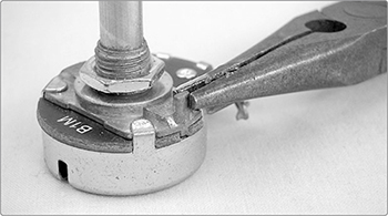
FIGURE A-4: Snapping off the anchor. Quick quiz: what’s the maximum resistance this pot offers, and does it have a linear or audio taper? 1
* NOTE: Resistors—fixed, variable, and otherwise—are basically indestructible; you don’t need to treat them with TLC as you start soldering.
The Gory Details: Voltage, Current, Resistance, and Ohm’s Law
In 1827, Georg Ohm described the relationship among voltage, current, and resistance in an electrical circuit. This was codified in Ohm’s law, often formulated like so:

This equation can be stated as “current equals voltage divided by resistance.” What does that mean? Well, imagine filling your bathtub. Your building’s water supply is the voltage (V), measured in volts. The faucet’s valve is a variable resistor (R), measured in ohms. The water flowing out of the tap is the current (I), measured in amperes and often shortened to amps.*
Assume the building’s water supply is stable. When the valve is wide open, it offers very little resistance, so the flow is high—which is to say there’s a strong current. Increase the resistance by closing the valve, and the current flowing from the tap decreases to a trickle. Close the valve far enough—in other words, increase the resistance as much as you can—and no current flows at all.
Plug some numbers into the equation, and you’ll see that this description holds in the formula: if V is fixed and R goes down, I goes up. If you decrease the voltage (the building’s water supply) while leaving the resistance the same (don’t touch the tap), then you know less water is going to flow out of the faucet. In other words, if R is fixed, then as V decreases, so does I.
Here’s where the tried-and-true “electricity is like water” analogy breaks down: a spike in water pressure isn’t a big deal; you might get sprayed in the face or slop water on the floor. But if you overload even simple electrical circuits like the ones in this book, they’ll overheat. An LED overloaded by a 9-volt battery will fail, melting and sparking in the process; it can easily damage adjacent circuitry or burn you. This is why it’s important to have an appropriate level of resistance, which is the thing hobbyists like us most often use Ohm’s law to figure out.
* Because an ampere is a very large amount of current—most houses run on 10 amp supplies, and less than 1 amp can stop the heart—you’ll usually see current measured in milliamperes (mA), which are 1/1000 of an amp.
Using Ohm’s law, we can calculate the best resistor value for a given circuit. Consider the simple indicator LED circuit used in many of the projects in this book (see Figure A-5).
To model this circuit, you need to rearrange Ohm’s law2 so that we can focus on resistance instead of voltage:

Next, break the voltage into two components:
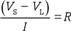
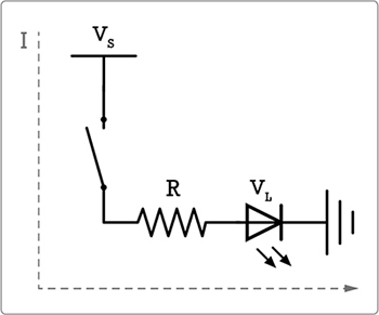
FIGURE A-5: A simple LED circuit
VS is the battery voltage, and VL is the forward voltage the LED requires to light up. For red LEDs, this is usually about 2 volts, but check your LED’s data sheet to be sure. The current in this circuit is determined by how many milliamps the LED draws, usually around 20 mA or 0.02 amps. (Again, check the data sheet for your LEDs to be sure.) Plug these in on the left side of the equation, and your ideal resistor value will pop out on the right:
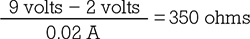
You want to buffer the LED with a 350 ohm resistor or larger. While 350 ohm resistors are rare, 470 ohm resistors are ultra-common, which is why I’ve buffered my 9-volt-driven power-indicator LEDs with 470 ohm resistors throughout this book.
What if you’d rather use a blue or white LED as the indicator for a project? Those usually have a forward voltage near 4 volts. Plug in the numbers, and you find the following:
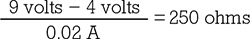
It would be safe to swap our red LED for blue or white because our 470 ohm resistor is higher than 250 ohms. But the downside is that you have almost twice as much resistance as you need, which might dim that dazzling blue LED more than you like. A value closer to 250 ohms would give a brighter blue LED. While 250 ohm resistors aren’t commonly manufactured, 240 ohm and 270 ohm resistors are. Go with 270 ohms. Although 240 ohms is within a ±5 percent tolerance of 250 ohms—and so, statistically, many “240 ohm” resistors are really 250 ohm resistors—always allow for a margin of error: fresh 9-volt batteries can measure up to 9.8 volts; I’ve seen rechargeables go over 10 volts. And you could wind up with one of the “240 ohm” resistors that’s really a 228 ohm resistor. Play it safe, and use a 270 ohm (red-violet-brown stripes) or higher resistor to buffer your white or blue indicator LED.
What if you need a specific resistor value you don’t have? For example, you thought you’d want to use blue LEDs—and so stocked up on 270 ohm resistors—but then changed your mind and decided you’d rather use reds. Never fear: if you need a specific resistor value that isn’t in your jackstraw-box-o’-tangled-resistors, you can do a little resistor math (see “Resistor Math: Series vs. Parallel” on page 92) to fake your way to any value you need.
Capacitors, or caps, are composed of two wires separated by a thin insulating layer called a dielectric (see Figure A-6). When voltage is applied to a cap, it stores energy like a water tower: pump the water in, and it stays put until you open the valve; give that water a path out of the tank, and it forcefully pours back out. Capacitance, or a component’s ability to hold this charge, is measured in farads, abbreviated F. A farad is a huge amount of capacitance, so most components are labeled in terms of picofarads (pF), which are smaller than nanofarads (nF), which are smaller than microfarads (μF). Most hobby-caliber circuit diagrams use microfarads. The smallest fixed caps—like the ones in this book—are often marked in a frustratingly opaque code, so see Table A-2 for a cheat sheet. For clarity’s sake, this book always works in microfarads.
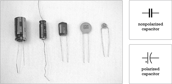
FIGURE A-6: Some capacitors—electrolytic, or polarized, caps (two on the left); Mylar-film cap (middle); ceramic-disc caps (two on the right)—and their symbols
TABLE A-2: Commonly Used Ceramic/Mylar Capacitor Markings and Their Values
Value (in μF) |
|
102 |
0.001 |
202 |
0.002 |
472 |
0.0047 |
103 |
0.01 |
104 |
0.1 |
105 |
1 |
205 |
2 |
Most small caps are little beige ceramic discs, sometimes called ceramic capacitors. Occasionally, they’re Chiclet-shaped plastic lozenges called Mylar capacitors because the dielectric is a thin Mylar film. The larger caps are barrelshaped electrolytic capacitors. Ceramic and Mylar caps are nonpolarized, meaning that it doesn’t matter which way which leg goes, while electrolytic caps are polarized and must be oriented properly in circuits. The negative leg of an electrolytic cap is always marked with a thick stripe, minus signs, or both. Added bonus: electrolytic caps are large enough to be labeled with their value, rather than relying on the terrible code. Most caps under 1 μF are ceramic or Mylar, and most over 2 μF are electrolytic.
Just as you can do “resistor math” to create a specific resistor that you don’t have handy, you can do “capacitor math” to get a custom capacitance. If you want to add capacitances—that is, for example, use two 10 μF caps to give you 20 μF of capacitance—then wire the two caps in parallel, as demonstrated in Figure 13-22 on page 239.
Alternatively, if you need a lower capacitance, you can use several caps in series. When you wire caps in series, add the inverse of their capacitances to get the inverse of the total capacitance, which sounds confusing but is exactly the same as the formula you use to calculate total resistance when wiring resistors in parallel (flip to “Resistor Math: Series vs. Parallel” on page 92 for all the excruciating details). In the case of our two 10 μF caps, wire them in series and you end up with the following:
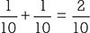
The resulting fraction reduces to 1/5, and you invert that to get your final capacitance: 5 μF. This is handy if you have a circuit that calls for a 5 μF cap but you have only 10 μF caps (once you start buying in bulk, this sort of thing happens more often than you’d expect).
Like resistors, caps are hardy components. Although it’s theoretically possible to apply so much current or heat to an electrolytic cap that it pops, I’ve never known anyone who did so accidentally.
Diodes and light-emitting diodes (LEDs) allow voltage of only a certain level or greater to pass. That is, the voltage must exceed the diode’s forward voltage. Diodes and LEDs will also let current travel in only one direction (see Figure A-7). In other words, they have polarity, and like all polarized components, they must be mounted in the proper direction to work. The stripe on a physical diode is closest to the diode’s negative leg, or its cathode, and it corresponds to the crossbar at the tip of the triangle on the diode symbol. On an LED, the negative leg is the shorter leg that’s on the side closest to the flat area on the LED lens’s edge.
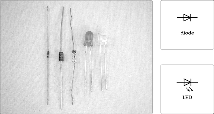
FIGURE A-7: Diodes and LEDs (left), and their symbols (right)
Thus far, we’ve discussed only passive components, which obstruct or modulate the flow of electricity, decreasing or slowing a signal. Transistors and integrated circuits are active components—they can be used to construct circuits that produce a power gain and increase the level of a signal. They can do this because they’re specially configured semiconductors. Simply put, conductors, like a piece of wire or a resistor, allow current to pass through them; insulators, such as the plastic coating on a 24-gauge wire, stop all flow of current; and semiconductors pass current in special ways.
Transistors are diodes’ fancy big brothers. Like diodes, they let current flow only if it exceeds the transistor’s forward voltage and only in one direction. The three-legged transistor works like a valve or switch: a low-current signal at the base controls a higher current that flows from the collector to the emitter. There are many kinds of transistors, but because the projects in this book use only common negative-positive-negative (NPN) transistors, that’s shown in Figure A-8.
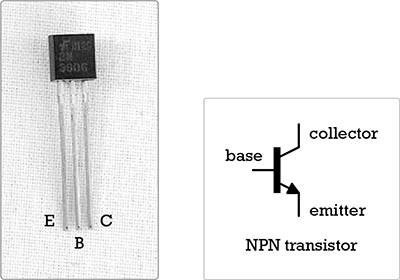
FIGURE A-8: An NPN transistor and its symbol
All semiconductors are sensitive to heat and static electricity. If you’re concerned about damaging them, use a heat sink when soldering them (see “Helpful Additions to the Standard Soldering Kit” on page 343).
Integrated circuits (ICs) are compact packages of semiconductors and passive components, prewired to perform a specific task (see Figure A-9). Anything an IC can do, a fistful of transistors, diodes, resistors, and caps—plus a few yards of bus wire and some circuit boards—can also accomplish. Because ICs rely on semiconductors, they’re also sensitive to heat and static, so handle them carefully. Avoid directly soldering to them and store them in the antistatic bags or tubes they’re shipped in.
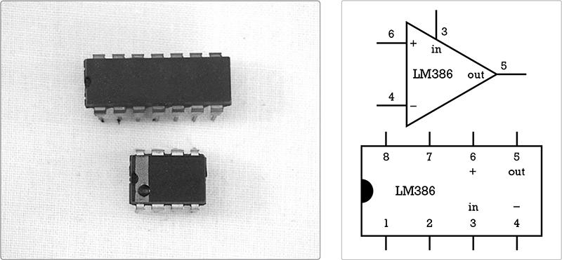
FIGURE A-9: Two DIP-style ICs (left) and symbols for the lower chip (right), which is the LM386 op-amp used in the Droid Voicebox (Project 6)
An IC in a circuit diagram is often depicted as a triangle or as a series of triangles for each of its logic sections. The numbers labeling the connections to the triangle correspond to the numbers of the IC pins. For clarity, I’ve used little drawings of the ICs in circuit diagrams throughout this book (a convention popular among hobbyists).
When ordering ICs from a catalog or website, always be sure to get the dual in-line package (DIP) version, like those in Figure A-9, as opposed to the surface-mount version. DIPs look like little rectangular insects standing on 8, 14, 16, or more straight little legs. They are small but still relatively easy to work with. Surface-mount chips are tiny little flat midges with short legs. They’re usually mounted on circuit boards by machines—you’ll find them on your computer’s motherboard—and you’ll go insane trying to learn to solder on them.
Electrical wire is described in terms of gauge, insulation, and core. The gauge of a wire is its thickness. Thinner wire has a higher gauge than thicker wire: 42-gauge winding wire used in commercial guitar pickups is as thin as a human hair, while 18-gauge copper wire is nearly as thick as a plastic cocktail straw. Conducting wire is labeled using the American Wire Gauge (AWG) Standard—for example, guitar pickup winding wire is labeled 42 AWG. Roughly speaking, when a wire’s diameter is doubled, the AWG decreases by 6, so 12 AWG wire is actually twice as thick as 18 AWG wire. This is why you can’t wind a very good pickup from common 20 AWG magnet wire: it’s actually four times thicker than real pickup wire and is thus significantly more difficult to induce a current through.
Wire can be either insulated or bare (uninsulated). Thicker insulated wire has flexible plastic insulation, but finer insulated wire—say around 30AWG and above—is usually enameled (coated in a shiny polyurethane varnish).
Finally, a wire is either solid core or stranded. Solid core wire is composed of a single solid strand, while stranded wire comprises several strands whose total combined cross-sectional area corresponds to the wire’s AWG. Solid core insulated wire is often called bell wire (especially in older DIY books), and stranded insulated wire is called hookup wire.
Speaker wire is a very common variety of 22-gauge stranded wire with thicker vinyl insulation. It’s used to connect hi-fi stereo components. You can find big coils of it for cheap in lots of odd places, like garage sales, thrift shops, big-box electronics stores, and so on. Speaker wire can often replace stranded wire in projects like those in this book.
Solid core wire is a little easier to solder into printed circuit boards (PCBs) because it fits nicely through the holes, but it can break easily with repeated bending when, for example, you open and close a case while checking a circuit, changing batteries, or making other adjustments.
Stranded wire, on the other hand, can be fiddly to thread through the holes on some circuit boards, but it holds up better to stress. Use solid core wire for connections that won’t move much, such as point-to-point connections on a board or when running between pieces of hardware mounted on the same surface. Use stranded wire if the wires need to flex a lot, like connections to a battery or to hardware running from a circuit mounted on the side of the box to hardware mounted on its top.
* NOTE: Bare 22- or 24-AWG solid core wire is often called bus wire and is great for running grounds, repairing broken traces on prefabricated PCBs, making jumpers, replacing lost eyeglass screws, and so on. It’s the all-purpose bailing twine of hobby electronics!
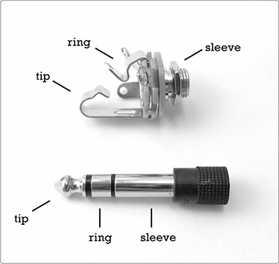
The 1/4-inch jacks you probably know as guitar jacks were first developed for manual telephone switchboards and are thus often still called phone jacks by hobbyists. (Be careful not to confuse these with RCA plugs and jacks, which are called phono jacks because they were the old standard on hi-fi stereo phonograph systems.) Mono 1/4-inch phone jacks are also called TS connectors because they have two lugs: one carries the audio signal and makes a circuit with the tip of a plug, and another connects the sleeve of the plug to the ground (see Figure A-10).
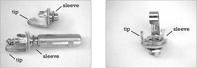
FIGURE A-10: Left: two 1/4-inch mono jacks—one with a plug inserted. Notice how the jack’s bent metal tongue fits into the notch at the plug’s tip. Right: a jack with labeled lugs. The right lug is connected to the sleeve, which connects to the circuit’s ground, and the other lug connects to the tip.
Stereo phone jacks and plugs are sometimes called TRS connectors. In this configuration, the sleeve still connects to ground, but the tip and ring each connect to an independent audio channel, allowing for stereo sound through a single cable (see Figure A-11). On a conventional cable, the tip carries the left stereo channel, and the ring carries the right.
FIGURE A-11: A 1/4-inch stereo jack and plug
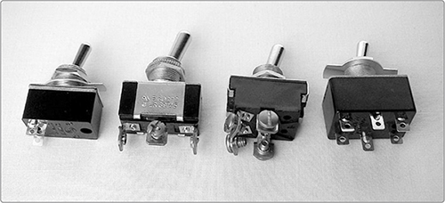
Switches are generally categorized by the number of circuits they can complete (how many poles they have), the number of positions they can switch between (their throws), and the mechanism for this switching (toggle, pushbutton, rotary, pull-chain, and so on). Your bedroom light switch, for example, is almost certainly a single-pole single-throw (SPST) toggle switch, where a single circuit is completed by a single throw of the switch. Other common toggle-switch configurations include the following:
Single-pole dual-throw (SPDT) Throw the switch one way to complete (or close) one circuit, and throw it the other way to turn off (or open) the first circuit and close a second circuit.
Dual-pole single-throw (DPST) Throw the switch to close two separate circuits simultaneously.
Dual-pole dual-throw (DPDT) Throw the switch one way to turn on two circuits and the other way to turn off the first two and turn on two more circuits.
Figure A-12 shows all four common varieties of toggle switch.
FIGURE A-12: From left to right: an SPST, SPDT, DPST, and DPDT switch. On the second and fourth switches, the common terminals—those shared by the circuits hooked to each pole—are in the middle.
Dual-throw switches come in two styles: some flip directly between two on states—one circuit is always on, but never both—and others allow you to park the switch in the middle, with both circuits off. Switches of the first type are often called on-on or changeover switches; those of the second type are center-off or on-off-on switches.
As for pushbutton switches, anything beyond a single throw is fairly rare. The big distinction here is between switches that are normally off so nothing happens until you press the button, like a doorbell, and those that are normally on, letting electricity through until you depress the button, like the switch that controls your refrigerator light. Switches that are off until pushed are also called normally open, which is abbreviated as NO. Switches that are on until pushed are also called normally closed, abbreviated as NC.
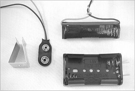
Figure A-13 shows a variety of battery clips and holders. Make a practice of buying a bunch of these when you find them cheap so that you have plenty on hand when you need them.
* WARNING: Never solder directly to a battery! Heating a battery can cause it to burst, releasing a mélange of chemicals that’ll burn exposed skin and that, depending on the type of battery, can catch fire when they contact air or moisture!
Invest in some rechargeable batteries. Newer nickel-metal hydride (NiMH) cells might seem pricey, but they’re worth it. They’re less toxic than the old nickelcadmium rechargeable batteries, can be recharged hundreds of times, and actually outperform regular alkaline batteries in high-drain applications, such as ultra-bright flashlights and digital cameras.
FIGURE A-13: Assorted battery holders and clips. The piece of metal at the far left is a 9-volt battery clip holder that keeps the battery from rattling around the enclosure.
The only tools you’ll absolutely need to build the electronics projects in this book are those included in the standard soldering kit, and even some of those can be faked.
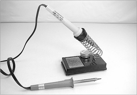
Get a 25-watt soldering iron with a chisel or pencil tip, as shown in Figure A-14. You can work on electrical projects with irons of 15 to 40 watts, but a 25-watt iron is probably the handiest. Cooler irons are great for soldering little components but will be a royal pain for soldering hardware, and hotter irons are great for quickly soldering plugs and jacks but can ruin ICs, LEDs, and diodes in a flash.
In terms of value, I recommend a Weller soldering iron. This brand is often sold at hardware stores, and a $25 Weller—the entry-level model—will vastly outperform any $10 generic counterpart. Weller irons typically last longer and heat more regularly, and the replacement tips are cheap and easy to find. You should also acquire a soldering iron stand; otherwise, you will burn yourself. In a pinch, you can lay the hot iron across a china plate or tile, but keep that up and you will eventually absentmindedly pick up the 700ºF barrel instead of the insulated handle. (I vividly recall the hot July night that I seared my index finger and thumbprints into the chrome of my first soldering iron. Fortunately, my hands were so sweaty that I dropped the iron before all the moisture had seared off my fingers. I bought a stand the next day, but my prints were etched into that iron a decade later when I finally invested in a decent Weller.)
FIGURE A-14: A 15-watt (bottom) and 25-watt soldering iron with a stand (top). The damp sponge in the stand is used for cleaning the tip, although many tinkerers prefer to use a copper scrubbing pad or old bolt instead.
Use thin rosin-core solder.3 Anything that’s specified for electrical work will fit the bill. It’s actually difficult to get the wrong kind of solder nowadays, as long as you avoid the acid-core solder sold at hardware stores. That stuff is used for working with copper plumbing, and it’ll ultimately corrode your electronics projects. Lead-free solder is a good idea, but even old leaded solder doesn’t pose much of a health threat, as long as you aren’t chewing on it. Soldering irons don’t get hot enough to vaporize lead. As a matter of good habit, always wash your hands (front and back, with soap and water) after soldering and before eating. (In general, you should always wash your hands—front and back, with soap and water—prior to eating. C’mon, people!)
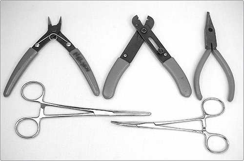
The diagonal cutters, wire strippers, needle-nose pliers, and clamps in Figure A-15 are also vital when soldering.
Diagonal cutters are fine snips used to cut the legs off of components after you’ve soldered them. Don’t confuse diagonal cutters with the heavy-duty wire snippers sold in hardware stores—these are a different sort of diagonal cutter, often called dikes. Dikes are too beefy to get in close to a circuit board. On the other hand, fine diagonal cutters are too delicate to be used on thicker-gauge wires, such as guitar strings, which will notch and ruin them. In a pinch, you can often use a pair of nail clippers in place of diagonal cutters.
Wire strippers are notched snips used for cutting through the plastic insulation of electrical wires while leaving the core intact. You can substitute a small pair of scissors, provided you’re very careful not to nick the wire’s core. Wire strippers are a very good investment.
FIGURE A-15: Clockwise from top left: diagonal cutters, wire strippers, needle-nose pliers, and two types of clamps
Needle-nose pliers are great for bending wires and component legs, seating components into hard-to-reach places, and loosening stubborn nuts, plugs, jumpers, and the like. Any set of small pliers will work well, and any cheap pair of needle-nose pliers will probably fit the bill.
The tools at the bottom of Figure A-15 are locking clamps of the same sort used by doctors, who call them forceps, hemos, or hemostatic clamps. They come curved or straight in a variety of sizes and are really handy for holding components while soldering. You can find them in many hardware stores, as well as lots of hobby and sports shops (folks also use them when building models or tying fishing flies).
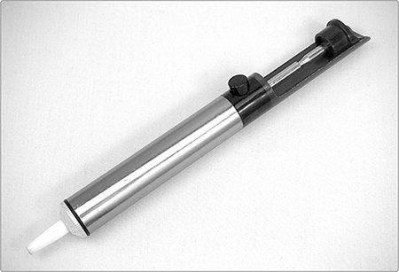
Although a desoldering tool is not mandatory, if you expect to be working on more than a project or two, you should invest in one. Desoldering tools come in a variety of forms, including desoldering braids—also called solder wicks—and comical squeezy bulbs, but the spring-loaded desoldering vacuum is by far my favorite (see Figure A-16). You’ll use your desoldering tool infrequently, but the moment you realize you’ve soldered a transistor backward, you’ll be very glad you bought one. (For more, see “Desoldering” on page 349.)
Finally, buy a roll of electrical tape. This black, rubberized tape can be used to secure wires, cover their soldered joints, and insulate bare solder points from each other. Insulation becomes especially important as you cram your projects into enclosures. In general, any enclosure that seems to be the perfect size when you’re planning a project will turn out to be a hair too small.
A tidy but trickier alternative to electrical tape is heat-shrink tubing. This is nylon or polyolefin tubing that you cut to length and slide over a wire prior to soldering. Once the joint is complete, slide the heat shrink up over the bare connection. Then heat the tubing by gently rubbing the barrel of your soldering iron along its length until it snugly hugs the connection.
FIGURE A-16: A desoldering vacuum, or “solder sucker”
Heat shrink comes in a variety of diameters and can be used for more than just insulating connections: it’s handy for bundling runs of wire, tidily packaging small projects, and sealing individual components together, as I did when building the optocoupler for the Bleepbox 8-Step Analog Sequencer (Project 16), which you can check out in Figure 16-23 on page 311. While electrical tape often gets gummy or falls off as it ages, especially if it’s exposed to heat or wildly fluctuating humidity, heat shrink makes for a rugged covering that basically lasts forever. You can see heat-shrink tubing in action in the Slinkiphone (Project 1); check out Figure 1-8 on page 10.
A heat sink, as shown in Figure A-17 (left), is clipped into the leads of a heat-sensitive component between the solder point and component body to prevent the component from getting overheated during the soldering process. (An alligator clip or a spare set of clamps will do as stand-ins.) You probably won’t need a heat sink very often in the course of normal soldering, but it comes in handy during desoldering, which tends to go slower and take more heat than soldering, or when you’re working with an expensive component you’re worried about frying.
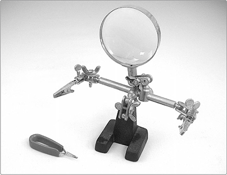
Although you can hold all your soldering with clamps, clothespins, your elbows, and stacks of books, most hobbyists eventually buy a helping hands jig, as shown in Figure A-17 (right). These are also used by model builders and fly fishers, so they might pop up for cheap at garage sales. They come with and without the integrated magnifying glass. I’ve never had to use the built-in magnifier, so I don’t consider it mandatory. But, as I get older I do increasingly find myself reaching for a small 10x magnifier of the sort used by field biologists (google doublet 10x pocket loupe for examples; you can get a great one for less than $15). They’re very handy when trying to read the labels on ceramic caps, diodes, small ICs, and so on.
FIGURE A-17: A heat sink (left) and helping hands (right)
Figure A-18 shows several common hand tools that make frequent appearances on the electronics tinkerer’s workbench. Jeweler’s screwdrivers4 are great for tiny screws or for prying ICs out of their sockets. The round side of a tapered half-round file is great for clearing burrs from holes drilled in metal cases, and the flat side takes the rough edges off of trimmed pot shafts. Finally, you can use a small hacksaw to cut down those pot shafts.
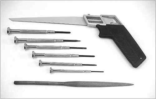
FIGURE A-18: A hacksaw (top), jeweler’s screwdrivers (middle), and a tapered half-round file (bottom)
Once you’ve decided you like creating electronic gadgets, go out and buy a digital multimeter. Figure A-19 shows one with an LCD display. Do not get an analog meter with the old-timey needle-and-dial gauge. They’re far more confusing to use and no longer cheaper than digital meters, which start at around $20.
Even the cheapest multimeters will accurately and precisely measure DC voltage, resistance, and current. Slightly nicer meters have special settings for testing continuity, which is handy, as well as forward voltage on diodes and LEDs, which only comes up occasionally but is a big time-saver. These nicer meters also can be used on AC circuits, which is useful if you need to fix something around the house or install a light fixture. For the projects in this book, a cheap multimeter will do fine.
Most multimeters come with a normal set of probes that look like thin knitting needles with bulky insulated handles and serve most purposes as you poke around testing batteries and troubleshooting circuits (see Figure A-20). Occasionally, you’ll need a pair of clip leads, which will free up your hands as you run tests—again, you won’t need them often, but you’ll be glad to have them when you do.
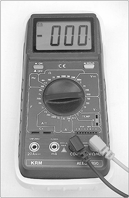
FIGURE A-19: A digital multimeter
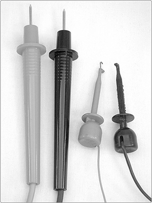
FIGURE A-20: A set of probes (left) and mini-clip leads (right). The latter are retractable hook leads, also called mini-clip jumpers, and are easy to clip to the leg of a single PCB-mounted component without creating a short circuit.
Also handy for troubleshooting or mocking up circuits are several sets of insulated test leads. These are also called jumpers, clip jumpers, alligator jumpers, and clip leads, and they look a lot like miniature automotive jumper cables. You can buy these ready-made—for example, Mouser part #290-1942-ND is a set of 10 color-coded insulated test leads at a great price. Or you can buy a bunch of individual alligator clips—such as Digi-Key part #290-1942-ND or Mouser part #835-501784—and get some practice soldering by making your own.
The keystone skills for an electronics tinkerer are soldering and its sinister twin, desoldering. This section will also discuss using a multimeter, building circuits, and troubleshooting projects.
If your soldering iron has a brand-new tip, tin the tip before using it: plug in the iron, and when the tip is nice and hot, melt some fresh solder onto it to coat the tip. This will prevent corrosion, which will otherwise eat away the tip pretty quickly.5 Then, you’re ready to start! Figure A-21 shows well-soldered and badly soldered joints.
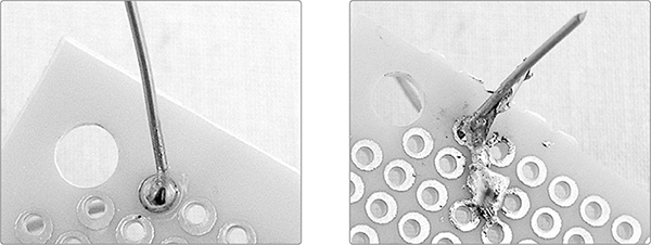
FIGURE A-21: Good (left) and absurdly bad (right) solder joints
A good solder joint is smooth and shiny, with enough solder to cover the connection, but not so much that the joint is encased in a round bead or droplet of solder. If you are soldering components to a circuit board, the joint will end up looking like a little volcano. A bad solder joint is dull, lumpy, or clumpy. Good soldering requires four steps, illustrated in Figures A-22 and A-23. Before you start, preheat your iron. Then, do the following:
Step 1 Make a solid mechanical connection between the components to be soldered.
Step 2 Wipe the iron’s tip clean of excess solder using a damp sponge or some scrap metal.
Step 3 Heat the joint for a few seconds and then touch some solder to the joint. The heated joint is what melts the solder, not the iron. Solder will flow naturally over and into a properly heated joint, like quicksilver. It’s very pretty. Don’t apply too much solder—once the joint is coated, you don’t need to add more—and don’t touch the solder directly to the hot tip of the soldering iron. Forcing hot solder onto cold joints will always make a bad solder joint.
Step 4 Let the joint cool and then snip off the excess wire. Leave the joint alone until it has cooled: don’t wiggle it to see whether it’s ready, and don’t blow on it to speed up the process.
Those are the basics! Now let’s look at the two most common soldering scenarios: point-to-point and circuit board.
If you’re doing point-to-point construction,6 as shown in Figure A-22, Step 1 means twisting the legs of the components together.
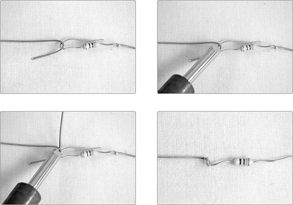
FIGURE A-22: Point-to-point soldering in four steps
If you’re using a circuit board, as shown in Figure A-23, Step 1 means you slide the component’s lead through the appropriate hole in the circuit board. Then, you bend the leg to one side so that it’s making contact with the board’s copper pad without touching other components or pads (molten solder will tend to slide up the hot wire and stick to whatever other metal it finds).
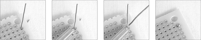
FIGURE A-23: Circuit-board soldering in four steps
Anytime you use stranded wire, start by tinning the wires: strip off the insulation, twist together the strands, heat the wire, and melt solder into it (see Figure A-24). This will make the wire easy to solder to other components or a PCB. The same should be done for the lugs and terminals on switches, jacks, and pots. Get each one nice and hot, and then coat it in a thin layer of solder. This will make it much easier to reliably connect wires or components to the lugs later. Small components, whose thin legs have very little mass, heat and solder very quickly. The lugs on hardware—especially switches and 1/4-inch jacks—are much beefier and take a good long while to heat up enough to melt the solder. By tinning lugs in advance, you can assure a good solder joint without abusing the smaller component.
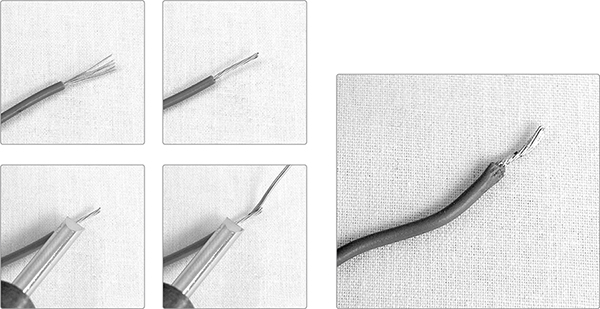
FIGURE A-24: Tinning a wire in four steps: strip, twist, heat, and apply solder. Voilà!
If you’ve invested in a chisel-tip soldering iron, you’ll find that the sharp edge of the tip is best for working with small or heat-sensitive components, while the broad, flat face, which has more surface area to conduct heat, will make soldering hardware much faster.
Desoldering can be a real pain, but you’ll do it much less frequently, and being good at it will save you time, misery, and money:
Step 1 Heat up your soldering iron, clean off the tip, and then apply heat to the soldered joint.
Step 2 When the solder flows, use your desoldering vacuum to suck up as much of the liquid solder as you can. (The tips of these vacuums are usually made of heat-resistant plastic.)
Step 3 Repeat once or twice.
Step 4 Reheat and wiggle the component free with a pair of needle-nose pliers.
You can desolder hardier components without the aid of a solder vacuum: just put on goggles, heat the solder joint, and tug at the component with your pliers, being careful not to flick hot beads of molten metal anywhere sensitive. The soldering vacuum can also be used to remove a solder bridge, which is anyplace that hot solder has inadvertently flowed between two components, causing a short circuit. Just heat the offending solder and suck it up. Killing a solder bridge without the aid of a desoldering tool, however, can be very tricky.
If you’re desoldering a heat-sensitive component, such as a transistor, play it safe and clip a heat sink to the component’s leg between the solder joint and the body of the component.
For the most part, you’ll use a multimeter for three tasks: testing batteries; identifying resistors, pots, and speakers; and testing continuity.
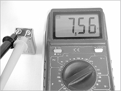
Set your meter for the proper DC voltage range. On most meters, you’ll need to use the 20-volt range for 9-volt batteries because they’ll overwhelm the lower 2-volt range and blow your fuse. Connect the black lead to the negative battery terminal and the red to the positive (see Figure A-25). Check whether the voltage is close to the value it ought to be. For most applications, a 9-volt battery is “dead” once it dips below 7.5 volts, and AAs or AAAs, which come out of the pack at 1.38 to 1.5 volts, are “dead” when they go below 1 volt.
FIGURE A-25: Testing a dying 9-volt battery
Slightly advanced maneuver: if a circuit is misbehaving, power it up and set the multimeter for the voltage range of the circuit’s power supply. For example, use the 20-volt range for a project powered by a 9-volt battery. Then, connect the multimeter’s black lead to the circuit’s ground and start poking around with the red lead to see whether the voltage levels throughout the circuit make sense. If you find an area that’s being starved of voltage, a short circuit or broken wire is likely the culprit.
To find the maximum resistance of an unlabeled variable resistor, first set the meter to an ohm range corresponding to your best guess about the resistor. Don’t worry if you’re wrong; there’s no way to damage the meter or pot doing this. Connect the leads to the edge lugs, ignoring the center lug (see Figure A-26). It doesn’t matter which lead goes to which edge lug. The multimeter will read the maximum resistance for the pot.
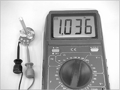
FIGURE A-26: Identifying a potentiometer’s resistance
Advanced Trick: Using Resistance to Identify Mystery Transformers
Small audio transformers are used to step up or step down voltage and current in order to, for example, drive a speaker. This is a shade more advanced, but if you get into building your own amps or experimenting with inductor-based wah pedals, you’ll probably end up mucking around with small audio transformers. You can use the ohms setting on your multimeter to figure out the turns ratio of an unlabeled mystery transformer. The ratio of turns between the transformer’s primary and secondary coils—which is also the ratio of the input-to-output voltages—is roughly equivalent to the ratio of the square roots of the resistances of each coil (round to two significant digits or so). To generalize this, where P stands for primary and S for secondary:
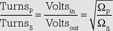
So if you need to figure out the turns ratio on a transformer, measure the resistance on each side, take the square root of each, and then reduce the fraction so that the smaller term is a 1—in other words, divide the big number by the small one. For the classic RadioShack 8–1000 ohm audio output transformer—that is, good ole part #273-1380, beloved by hobbyists for decades—this calculation looks like so:
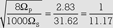
Is it exactly right? Clearly not, but it’s a very useful approximation and spot on after you round to the nearest turn.
You can use this same method to identify unlabeled speakers. Most projects like the ones in this book call for 8 ohm speakers, so you should be looking for speakers that measure 8 ohms between their terminals.
If two points in a circuit have continuity, then there’s an unimpeded flow of electricity between them. To test continuity, choose an ohms setting7 and connect one lead to each end of something that should conduct electricity, such as the tips at the ends of a guitar cable or two ends of a dodgy length of wire (see Figure A-27). If the meter reads anything other than 0, there’s a problem. This is also a good way to figure out which lugs are which on a complicated switch, such as the many-pole, many-throw selector knobs that can be salvaged from old medical and computer equipment.
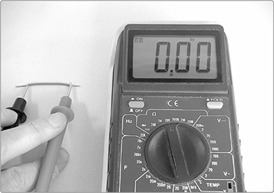
FIGURE A-27: Testing continuity
If your multimeter has a built-in continuity tester, it’s even easier. Set the meter to test continuity—a mode that often doubles as an LED/diode tester and is represented on the dial as either the diode symbol, a little “circle making a noise” glyph akin to a Wi-Fi symbol, or both. Then, touch your leads to the two points that you’re inspecting. If the multimeter makes a continuous tone, you have continuity. If it remains silent, you don’t.
* NOTE: If you are checking continuity on a circuit, pull the batteries first, lest you damage your meter or mislead yourself with nonsense readings.
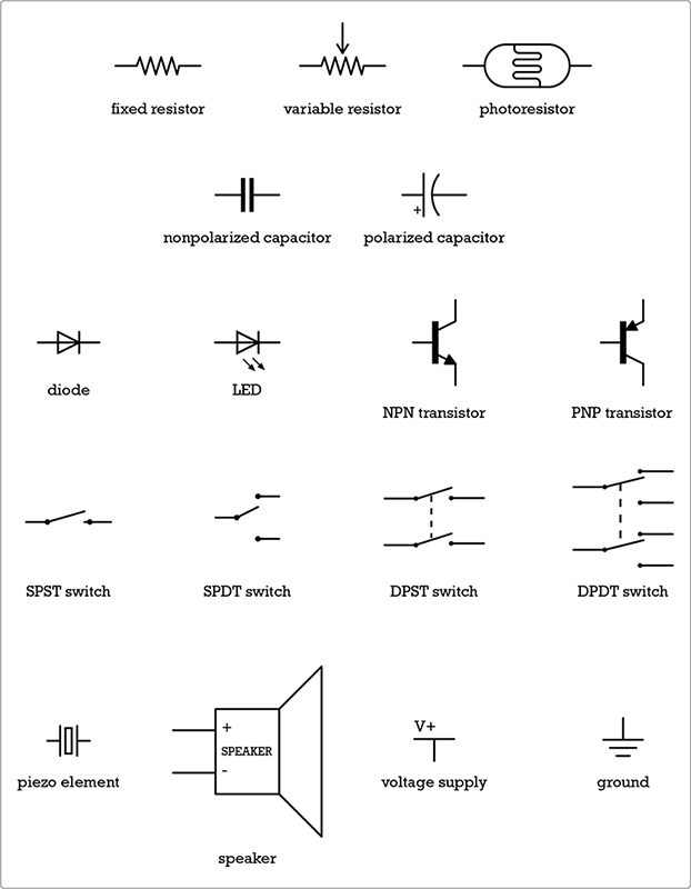
A circuit diagram is a map of the functional relationship between electrical components. It’s drawn using symbols, such as those shown in Figure A-28. A circuit diagram doesn’t tell you the actual physical layout of the circuit. In most simple projects, if the components are connected correctly, it doesn’t really matter what is where. In some designs, especially for audio circuits, the physical layout of some parts of the circuit are sensitive; if that’s the case, it’ll be noted in the build notes, or the designer will provide a separate layout diagram showing exactly which physical component should be placed where on the circuit board.
Most circuit diagrams flow either from top to bottom or left to right, with positive voltage or signal sources at the top or left and ground connections and signal outputs at the bottom or right. To minimize ambiguity, designers do their best to avoid having lines cross or touch unnecessarily in their circuit diagrams, but it’s sometimes unavoidable. If you’re looking at a schematic and there’s a dot at the intersection where two lines meet, you can assume this denotes an actual electrical connection between those components. If the lines simply cross with no dot, this probably doesn’t represent a connection. For an example of this distinction, flip back to the circuit diagram for the Droid Voicebox, Figure 6-4 on page 77.
FIGURE A-28: Common component symbols used throughout this book
Before getting out your soldering iron, it’s a good idea to test circuits on a solderless breadboard (see Figure A-29—you won’t find this breadboard on your kitchen counter). Breadboards are cheap and come in many sizes. Most come packaged with a selection of precut insulated wire jumpers to connect everything together as you prototype your project—handy! But if yours doesn’t, no problem: you can just use little snips of wire. A nice feature of the breadboard is the central divide, which is spaced to hold an IC, giving easy access to each IC pin. This makes it a lot easier for you to hook things up correctly when you start tinkering with ICs.
Once your circuit is working as expected, you’ll want to make it permanent by soldering all of the connections. If you use a permanent breadboard–style circuit board, like the one shown at the top of Figure A-30 or one of the Adafruit Perma-Proto PCBs, then you can directly transfer your prototype breadboard layout to the PCB with no muss or fuss.
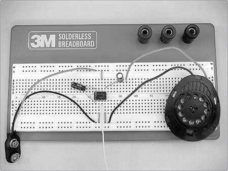
FIGURE A-29: A breadboard with a sample circuit. Specifically, this is the “Dirt-Cheap Amp” on page 363, with the optional gain-maximizing capacitor running from pin 1 to 8. The white wire running from pin 3 out of frame at the bottom carries the input signal. Notice that the bottom and top rails of the breadboard are being used as a common ground and power rail, respectively.
To build a circuit, begin by gathering and sorting all the components you need for the project. You don’t want to inadvertently grab the wrong resistor or IC in the heat of the moment. A cardboard egg carton is great for sorting components for a small project, but avoid Styrofoam cartons if you’re using ICs. Styrofoam can hold a static charge, and many ICs are sensitive to static electricity. After you’ve sorted your components—and labeled them with scraps of paper at the bottom of each egg compartment—start building the circuit. It’s usually easiest to place the ICs or transistors first and then build out from there.
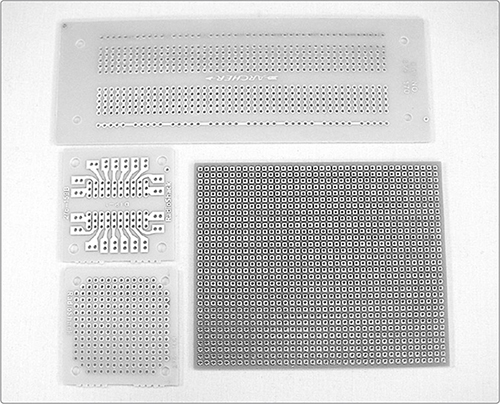
After you have the circuit working on the breadboard and you understand why it works, you can build it for real, either dead-bug style—soldering the components directly to each other, which is very compact but often ugly and difficult to repair or troubleshoot—or on a printed circuit board (PCB), a sturdy, nonconductive board with copper pads and traces etched onto one side (see Figure A-30).
FIGURE A-30: A selection of PCBs. A permanent breadboard–style circuit board is shown at the top of the figure.
If a circuit works fine on the breadboard but malfunctions when it’s built, check for the following:
ICs improperly seated in their sockets: Carefully pull any offending chips out of their sockets, orient correctly, and reseat them so that they’re flush to the socket.
Short circuits: Look for scraps of stray wire resting on the circuit board or uninsulated components, especially hardware, touching each other inappropriately. Remove or separate.
Solder bridges: Reheat and remove excess solder.
Bad solder points: A good solder point is smooth and shiny; bad ones are rough, brittle, or chunky (see the right photo in Figure A-21). Redo bad joints.
Reversed polarized components (electrolytic caps, diodes, LEDs, transistors, and ICs): Remove and replace. If you powered the circuit with the component oriented incorrectly, it may have been damaged.
Missing ground connections or incomplete ground: Complete now.
Reversed potentiometer connections: Redo them now.
Bad hardware: Disconnect any suspect hardware and check it individually. Sometimes you’ll discover a faulty switch, damaged pot, or bent jack. Replace malfunctioning parts.
Shorts to ground: This is especially annoying in tight enclosures. The circuit may function normally on your workbench, but when you close the box, components or wires get squeezed together, creating a temporary short. Prevent shorts by running lengths of shrink tube over bare wires or by using a judicious application of nail polish or Plasti Dip, which will act as an insulator when it dries. You can also cover the bottom of the PCB or conductive portions of the enclosure with strips of duct tape.
Ground-tip continuity: With the batteries removed and nothing plugged in, check whether you have continuity between the ground and tip on the input or output jack. If so, look for short circuits, especially around the jacks, switches, pots, and so on. To remedy this, tighten or reorient the hardware, or wrap a bit of electrical tape around obvious shorts. Also check for bent jacks causing a short circuit. Replace damaged hardware.8
Voices from beyond: If an audio project is noisy or picks up AM radio, baby monitors, intercoms, and so on, check that the audio signal lines are either shielded, as discussed in the footnote on page 215, or less than 8 inches long. Err on the side of caution and keep all wires carrying audio signals under 6 inches. The exception is lines running from an amplifier circuit to its speaker, as this amplified signal is strong enough to drown out any interference that might creep in at that point.
Finally, always check your batteries! Folks tend to assume that a circuit with good batteries works, one with dead batteries doesn’t work, and one with dying batteries works intermittently. This is rarely the case. Dying batteries (especially those hovering right around the threshold I mentioned in “Testing Voltage” on page 349) can cause circuits to perform erratically or exhibit really odd behavior. This is especially the case with any circuit that includes an IC. So if your circuit is being just straight up bonkers, check the battery voltage.