This appendix provides a handful of schematics for circuits that might come in handy as you continue to tinker and explore, including generic versions of all of the oscillators we’ve built in this book, a basic amplifier, a stripped-down preamp, and some useful filters and effects. Enjoy!
Have a switch you aren’t sure is working right? Or a multi-pole switch whose terminals you need to sort out and label? What about a pile of instrument cables that look fine but might have gotten slammed in a car door too many times? A continuity tester, which tells you whether two points in a circuit are electrically connected, is your best friend in these situations.
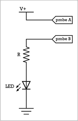
Most digital multimeters have a built-in continuity tester, but maybe yours doesn’t, or maybe your meter isn’t handy. No worries! In about a minute you can build the simple continuity tester shown Figure B-1.
Use a red LED in this circuit. If you power this with a 9-volt battery, then use a 470 ohm resistor for R. If you use a 3-volt supply—that is, a pair of 1.5-volt AA or AAA batteries, or a single 3-volt watch battery, such as a CR2032 or CR2016—then use a 100 ohm resistor.
The probes are just insulated wire in any old gauge, so cut them as long as you like. You could even use a pair of alligator jumpers clipped directly to the circuit. Either way, attach one probe to the red lead from your battery pack and the other to the stray leg of resistor R. Now touch the probes together; the LED lights up. Separate them, and the LED goes dark. To test for continuity between two points (such as either end of a suspect guitar cable), touch one probe to each. If the LED lights up, you have continuity. If not, then something is broken between points A and B.
FIGURE B-1: A simple continuity tester circuit
Jack power is an easy way to eliminate power switches from effects and electronic instruments. In order to accomplish this, swap out the existing mono jack for a stereo jack wired to function both as an input/output and as an automatic power switch (see Figure B-2). Then, just plug in the instrument or effect to turn it on and unplug to turn it off.
To install jack power, follow these steps:
Step 1 Omit the power switch and run the positive battery lead directly to the circuit.
Step 2 Instead of connecting the battery’s negative lead to the circuit’s ground, connect it to the ring lug of the stereo jack.
Step 3 Wire the circuit’s input or output to the tip of the stereo jack, just as you would with the original mono jack.
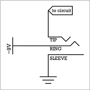
FIGURE B-2: To add jack power, wire a stereo jack to function as both a power switch and an input/output.
Now when you plug the instrument into your standard guitar cable, which is a mono cable, it will complete the ground, activating the circuit.
Meditating upon simplified versions of the oscillators used in this book’s synth projects can be instructive. They might come in handy when you start building your own sound sculptures, custom synths, cookie-jar burglar alarms, or other noise projects. With any of these, you can swap the pitch or rate pot for some other resistor. You might try a different potentiometer value; use a single fixed resistor to hardwire a specific tone; or swap in a photoresistor (thus transforming your synth into a phototheremin), a set of body contacts, a force-sensitive resistor, a flexible resistor, or some other variable-resistance scheme. Whatever suits your project will suit these oscillators just fine.
The LM386 is conventionally used to build small power amps, like the Dirt-Cheap Amp in Figure B-7 on page 363. But it can also be used to build a variety of oscillators; the simplest of these is shown in Figure B-3. (Find an LM386 datasheet online for other examples of pretty cool basic audio oscillators you can build around this IC.)
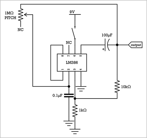
FIGURE B-3: A bare-bones version of the LM386-based square-wave oscillator used in the Droid Voicebox (Project 6).
This circuit has a higher part count than similar square-wave oscillators built around other chips, but it can also directly drive a wider variety of speakers (no amplifier needed) and can be a good deal louder. Toy with any of the component values to see whether the results please you.
Both the Single-Chip Space Invader Synth (Project 15) and the Bleepbox 8-Step Analog Sequencer (Project 16) are built around the CD4093, a standard logic IC that we mildly abuse in order to make it chirp and warble for our pleasure. The CD4093 has four identical logic sections; thus far, we’ve always used two sections per oscillator to guarantee a nice, crisp square wave, even at very high rates. But you can get a perfectly usable oscillator from just one section of the chip.
Figure B-4 shows the simplest single square-wave oscillator you can build on a CD4093. Despite its very low part count, this single square-wave oscillator is very reliable and perfectly suitable for many projects. A single-section oscillator like this results in a square wave that gets a little distorted at higher rates, leading to a fuzzier voice, but otherwise works fine.
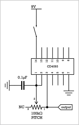
FIGURE B-4: The minimal CD4093 single square-wave oscillator
Figure B-5 shows the circuit that gives you the most bang for the buck from a CD4093: four independently controlled oscillators on a single chip.
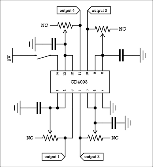
FIGURE B-5: The maximal CD4093 four square-wave oscillator
Each oscillator in this circuit is a lo-fi single-section oscillator, but having more oscillators gives you a pretty wide sound palette. You can run each output to its own jack/amp/whatever—resulting in four completely independent synthesizers on a single chip. Or you can mix the outputs via diodes, as we do in the Single-Chip Space Invader Synth (Project 15) and the Bleepbox 8-Step Analog Sequencer (Project 16), to sculpt richly textured cascades of chiptune glitchtastrophe. Or you can mix them using resistors (start with 10k ohm, either fixed or variable) for a thick, roaring wall of sound. As always, experiment with the potentiometer and capacitor values to find combinations you like.
Because the 555 timer chip is so cheap and common, it’s where many folks begin with their oscillator experiments. The much-loved Atari Punk Console synth is built on a dual-555 chip—that is, a single chip with two independent 555 timers built in. The result is something like a junior version of our CD4093-based dual-oscillator synth (the one we used in the Space Invader Synth and the Bleepbox). If you’re looking to build a cheap and effective tone-generating audio oscillator using a 555, there’s a circuit for just that in Figure B-6 (left). Figure B-6 (right) provides a simple 555-based metronome circuit, very similar to the clock we built for the Universal LFO (Project 13).
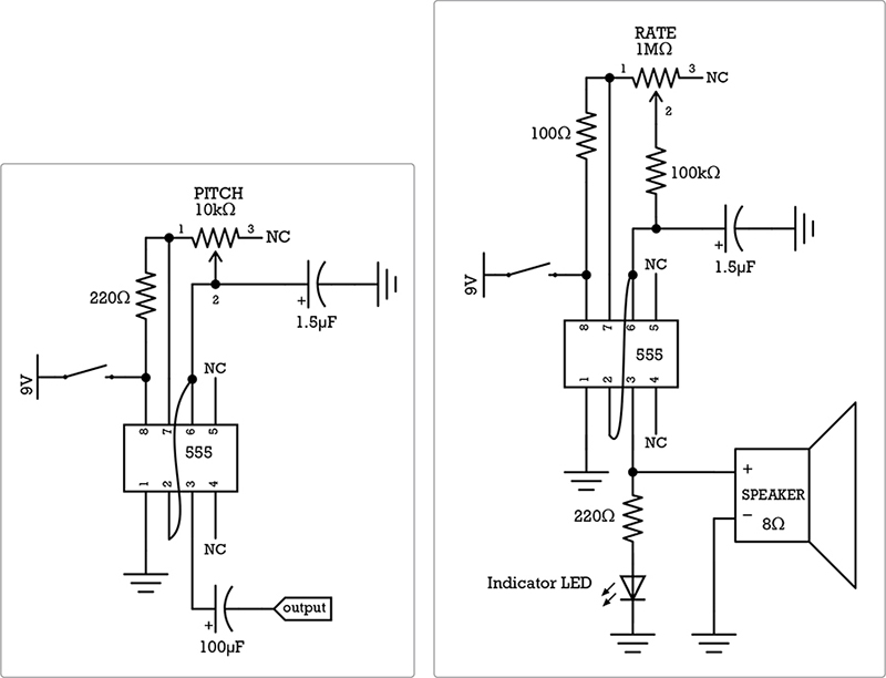
FIGURE B-6: A 555 tone-generating square-wave oscillator (left) and a basic 555-based metronome (right). Note that the tone generator can output either to an amplifier or directly to an 8 ohm speaker.
Most of the projects in this book are more fun when you can make them louder. This section provides circuits for simple, crafty amps and preamps.
Figure B-7 is my go-to, all-inclusive battery-powered amplifier, also called a power amp. This is what you’re thinking of when you think of a guitar amp: you plug an instrument in, and it amplifies the signal and pumps it out of a built-in speaker (which in this case is an 8 ohm speaker, although values between about 3 ohms and 16 ohms often work fine). Full build instructions for this amplifier are included in my first book, Snip, Burn, Solder, Shred. One quick mod: want to make this amp louder? Instead of running a plain piece of wire from pin 1 to pin 8, use a 10 μF capacitor, with the negative cap leg connected to pin 8 and the positive to pin 1.
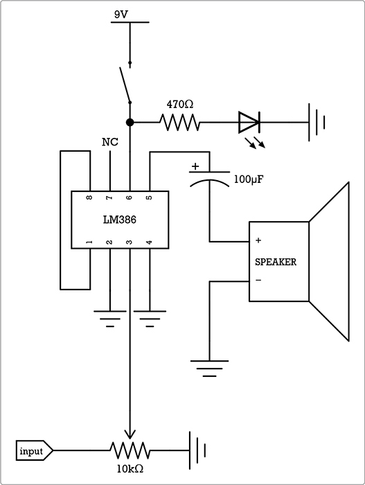
FIGURE B-7: The Dirt-Cheap Amp
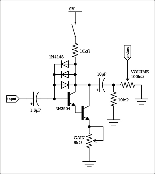
The Mud-n-Sizzle Preamp (Project 12) combines a simple transistor-based preamp and basic low-pass filter. Figure B-8 shows the preamp section as a standalone circuit, which can be easily built into another project or used as a basic preamp on its own.
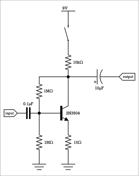
FIGURE B-8: A generic transistor-based preamp
Figure B-9 shows the Two-Transistor Fuzztone, a souped-up hot-rod version of that basic transistor preamp shown in Figure B-8, optimized for gain, fuzz, and stadium-rocking bravado. As with the Dirt-Cheap Amp, full build instructions for the Two-Transistor Fuzztone—as well as some other electronics effects and instruments—are included in my first book, Snip, Burn, Solder, Shred.
FIGURE B-9: The stadium-rocking Two-Transistor Fuzztone
These filters and mixers are super simple, but they can really transform your sound. The filters allow you to alter the ratio of high- and low-frequency elements in your signal, modifying an instrument’s voice or shifting the prominence of different instruments in a mix. The mixers allow you to mix several sound sources together to a single output—very handy if you have three instruments but only one PA amp or input on your recorder. The panners/splitters are specialized, single-knob mixers, making it possible to run two sound sources into a single input or to divide a single source between several destinations.
When you “crank the bass” on your car stereo, you’re really cranking a low-pass filter: it cuts the highs and lets the lows through, leaving you with a window-rattling rumble. Figure B-10 (left) shows a robust little variable low-pass filter—the same one that’s integrated into the Mud-n-Sizzle Preamp (Project 12).
In addition to boosting the bass in a mix or giving your guitar a smooth, jazzy tone, low-pass filters are enormously handy in synth projects. Simple square-wave synths like the ones we’ve built in this book tend to be very buzzy or reedy, which can get annoying in certain frequency ranges or at high volume. A low-pass filter will smooth out a square wave, imparting a smoother, rounder tone more characteristic of a sine-wave synth or an old-school 1950s theremin.
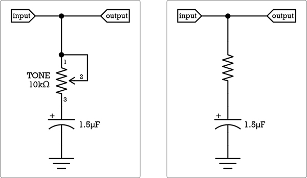
FIGURE B-10: A generic low-pass filter, adjustable (left) and fixed (right)
You can package a low-pass filter as a stand-alone passive effect (no batteries necessary!) or build it into projects. It can be adjustable, or you can use a fixed resistor of your choosing to lock in a specific sound, as shown in Figure B-10 (right). Fixed low-pass filters are generally built into projects, while adjustable low-pass filters can either be built in or serve as fun and useful stand-alone effects. Most commercial amps include a built-in adjustable low-pass filter.
A standard volume control is a rudimentary filter all by itself: it doesn’t reduce all frequencies equally. You tend to lose the highs first, which muddies the tone and leads to a loss of presence—that is, the guitar doesn’t just sound quieter but also less important. One solution long embraced by guitarists—and included in many commercial electric guitar designs—is to short a cap across the volume control (as shown in Figure B-11).
This makes the volume control into a sort of specialized high-pass filter: it leaks extra highs into the output as you turn down the volume, maintaining the instrument’s presence even as you decrease the volume. The cap can be any of a variety of values, depending on the instrument and your tastes. Start with something in the 0.001 μF to 0.002 μF range and experiment.
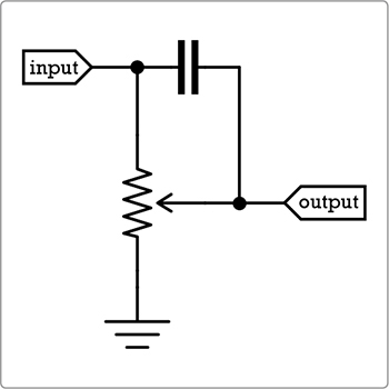
FIGURE B-11: The classic extra-presence volume control mod
A single pot can be used as a simple crossfade-style mixer. Crossfade mixers work in one of two ways: you can mix two inputs to a single output, as we did with the two pickups in the Twang & Roar Kalimba (Project 11), or you can divide a single input between two outputs. Imagine the latter as a splitter, instead of a mixer, dividing your signal between two effects.
Figure B-12 shows both options in their most generic forms.
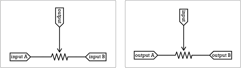
FIGURE B-12: A two-in/one-out pan-pot mixer like the one in the Twang & Roar Kalimba (left) and a one-in/two-out pan-pot splitter (right)
One cool use of the one-in/two-out pan-pot splitter is as a panner, dividing the output from a single battery-powered power amp—like the Dirt-Cheap Amp in Figure B-7—between two speakers (see Figure B-13).
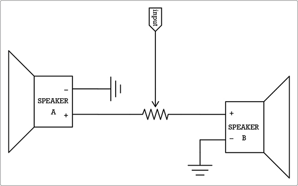
FIGURE B-13: Controlling two speakers with a single pan-pot
For example, build the Dirt-Cheap Amp, but instead of directly connecting a speaker, run that output—the negative leg of the 100 μF cap—to the input of the pan-pot circuit in Figure B-13. Then, use especially long runs of speaker wire to connect the pan-pot’s two speakers. Separate the two speakers by a good distance—for example, put them on opposite sides of a room—and pan between them for a swooshing rush or fast ping-pong effect. If you put the speakers back to back, panning across them repeatedly—perhaps with a modified Universal LFO (Project 13)—you can create a rudimentary “Leslie amp”–style organ swelling effect.
If you have several lo-fi instruments or effects you want to pump into the same piece of gear—perhaps in order to record them together or so they can share an amp or mesh into a greater sound system or electro-musical scheme—you need a multichannel mixer to combine their signals. The simple passive (i.e., unpowered) mixer shown in Figure B-14 will mix several signals with a minimum of fuss. Just plug the sound sources into your inputs and then the destination (such as the amp or recording gear) into the output. Added bonus: you probably already have all the necessary parts to build this kicking around the bottom of your components bin.