This project combines a simple, if idiosyncratic, 8-step analog sequencer with a modified version of the two-oscillator Single-Chip Space Invader Synth (Project 15). A sequencer is any device that controls and automates a sequence of events. Although originally applied strictly to industrial contraptions, the term has now been entirely swallowed by electronic music, where sequencers are responsible for funky bass lines, lush synth pads, and rock-steady robot drumbeats.
The analog in this project’s name refers to both the pair of analog oscillators that provide the synth’s voice and the sequencer controls themselves, all of which give you access to the full sweep of states their components can create, rather than limiting you to a set of discrete, predetermined settings. The 8-step means that the sequencer repeats a steady pattern of eight individually controlled pitches, enough for a single sprightly bar of music or a pair of alternating 4-step bars. This might not seem like much by modern standards, where 16 steps is the norm for a hardware sequencer and a computer can hold a functionally infinite number of steps. But it’s perfect for a performance sequencer meant to be tweaked on the fly by a live musician working a groove.
* NOTE: You’ll see more musical terminology in this project than you have in the others. If you find yourself confused about bars, 16th notes, rests, and so on, flip to Appendix C.
Hear the Bleepbox in action in the samples at http://www.nostarch.com/jamband/.
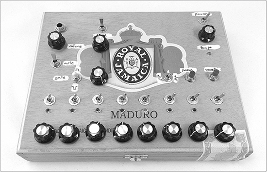
FIGURE 16-1: The finished Bleepbox 8-Step Analog Sequencer
Build Time
 About 3 hours
Tools
A standard soldering kit (See page 340.)
A ruler that shows 1/4-inch increments or smaller
A Sharpie or other permanent marker
An electric drill with bits (You’ll probably need 3/16-inch, 5/16-inch, and 3/8-inch bits.)
Other tools to work your enclosure (If you’re using a wooden enclosure, you’ll want sandpaper and possibly files to clean up drill holes.)
A multimeter or continuity tester (See “Using a Multimeter” on page 349 or “Super-Basic Continuity Tester” on page 357.)
An amp and instrument cable for testing the synth
(Optional) Foam-backed double-sided tape or hardware to mount the circuit in its enclosure
(Optional) A hacksaw for trimming down potentiometers with long shafts
* NOTE: For clarity, I’ve split the supplies list into two parts: one for the 8-Step Sequencer and the other for the modified Space Invader Synth that the sequencer controls.
Supplies for the 8-Step Sequencer
A CD4017 integrated circuit, such as Digi-Key part #296-2037-5-ND
A 16-pin IC socket
A 555 timer IC, such as Digi-Key part #296-1411-5-ND or Mouser part #595-NE555P
An 8-pin IC socket
Two 1N4148 silicon diodes (Mouser part #78-1N4148 is shown in Figure 16-2, although any generic 1N4148 or 1N4150 is fine.)
10 red LEDs
Nine 220 ohm resistors (red-red-brown stripes)
Two 10k ohm resistors (brown-black-orange stripes)
A 470 ohm resistor (yellow-violet-brown stripes)
Nine 1M ohm variable resistors (Variable resistors are also called potentiometers or pots; Mouser part #313-1000F-1M is shown in Figure 16-2, but you can use any 1M ohm pot with a linear taper. See “The Gory Details: Audio Taper vs. Linear Taper” on page 327 for details.)
A 100k ohm variable resistor with a linear taper
10 control knobs that fit your variable resistors
A 1.5 μF electrolytic capacitor
Nine small SPST toggle switches (You can use Mouser part #108-MS550K, for example, but any similar switch will work.)
A small SPDT toggle switch with two on positions (These are often called on-on or changeover switches. Something like Mouser part #108-1MS1T2B3M2QEEVX will work.)
A small center-off SPDT toggle switch (This has three positions: one side turns on one circuit, the other turns on another circuit, and the center position turns off both circuits. These are often called on-off-on switches. Something like Mouser part #612-100-C1111 will work.)
Two SPST pushbutton switches, such as Mouser part #103-1012-EVX or nonilluminated doorbell buttons
A 9-volt battery
A 9-volt battery clip
24-gauge insulated hook-up wire (Stranded wire is fine. It’s best to have several colors.)
22- or 24-gauge bare bus wire (This is uninsulated solid core wire.)
An Adafruit Perma-Proto Quarter-sized Breadboard PCB (Adafruit product #589 or Maker Shed product #MKAD48)1
Duct tape and electrical tape, or heat-shrink tubing
A sturdy enclosure (Cigar boxes are good here, as are plastic lunchboxes. See “On Enclosures” on page 214 for more options.)
(Optional) A 9-volt battery holder clip, such as Digi-Key part #71K-ND or Mouser part #534-071
Supplies for the Modified Single-Chip Space Invader Synth
* NOTE: It’s perfectly possible to modify a prebuilt Space Invader Synth to work here; check Step 23 on page 310 for details on the changes that need to be made.
A CD4093 integrated circuit, such as Digi-Key part #296-2068-5-ND
A 14-pin IC socket
Two 1N4148 silicon diodes (Mouser part #78-1N4148 is shown in Figure 16-2, although any generic 1N4148 or 1N4150 is fine.)
A photoresistor (This might also be called a light-dependent resistor, a cadmium sulfide (CdS) cell, or a photocell. Flip to “The Gory Details: Selecting the Right Photoresistor” on page 328 for some important tips on selecting a photoresistor for this project.)
A 220 ohm resistor (red-red-brown stripes)
A 470 ohm resistor (yellow-violet-brown stripes)
A 10k ohm audio potentiometer (This is a variable resistor with an audio taper; see “The Gory Details: Audio Taper vs. Linear Taper” on page 327.)
A 500k ohm variable resistor with a linear taper
Two control knobs that fit your variable resistors
Two 0.1 μF capacitors (marked 104)
Two small SPST toggle switches (You can use Mouser part #108-MS550K, for example, but any similar switch will work.)
A 1/4-inch mono phone jack, also called a guitar jack
An Adafruit Perma-Proto Quarter-sized Breadboard PCB (Adafruit product #589 or Maker Shed product #MKAD48)

FIGURE 16-2: Tools and supplies; the parts for the modified Single-Chip Space Invader Synth are clustered in the lower-right corner of the bottom image (not shown: amp, instrument cable, hacksaw, marker, and multimeter)
The Bleepbox 8-Step Analog Sequencer is definitely the most complex project in this book, so let’s take a tour of the controls shown in Figure 16-3 before we begin.

FIGURE 16-3: The Bleepbox control panel
In the upper left, we have the output section, with an output jack, output volume control, and output mute. These are pretty self-explanatory.
To the right of the output controls are the modulation controls, which give the synth its signature phat chiptune timbre. When you turn the mod oscillator off with the mod switch, you hear a pure square wave. With modulation turned on, you hear the result of the mod oscillator and the pitch oscillator interacting with each other, giving you a wide range of effects and textures. The mod rate knob controls the speed of the mod oscillator.
Below the modulation controls are the controls for the Bleepbox’s automated clickgating effect, which is distinctive to this design and a bit of an odd duck. When you flip the click-gate switch either up or down, it creates a steady rhythm within your pattern by inserting two evenly spaced clicks in each step, one at the beginning and one in the middle. It’s similar to the click track you hear in recording software or a very stripped-down version of a drummer keeping the beat on the closed hi-hat. This click rhythm isn’t muted by the output mute.
When the click-gate switch is in square-up mode, as noted by the label, it accentuates the first half of each step and nearly mutes the second half. In square-down mode, it mutes the first half of each step while accentuating the second half for a funky “riding behind the beat” feel. In the middle position, the click-gate effect is off. The depth of this effect, or how emphatic it is, can be adjusted with the depth knob to the right of the switch.
The rows of eight switches, eight LEDs, and eight knobs along the bottom edge form the step controller section. Each switch-LED-knob cluster controls a single step in the sequence. Each step’s indicator LED indicates when the step is active and gives a relative sense of that step’s pitch (brighter light = higher pitch). The pitch control knob sets the pitch for that step. The toggle switch is an overdrive mute, another odd-duck control: it mutes the corresponding step by running the pitch oscillator too fast to be audible. Because our sequencer slides between pitches rather than jumping from note to note (trés analogique!), muting in this fashion leads to the voice sliding zappingly back into the mix, rather than simply popping back on.
The power switch is in the upper-right corner of the sequencer control panel. Beneath that is the tempo control, which sets the rate of the sequence, ranging from a sludgy 50 beats per minute (bpm) up to self-oscillation. Self-oscillation means that the pattern runs so fast it becomes its own complexly layered pitch, a sort of meta-voice of the synth. In this case, the self-oscillation sounds a lot like an angry robo-wasp shifting her space-race speederbike during the final lap of a post-apocalyptic motocross race. The pause and reset buttons sit below this tempo control. Pause holds the pattern at a specific step, humming the chosen pitch. Reset restarts the pattern.
Finally, the switch marked 3/4 and 4/4 is the rhythm selector. It allows you to choose between an 8-step pattern, which is recognizable as the 4/4 rhythm you hear in almost any pop song, and a 6-step pattern, which naturally falls into a 3/4 rhythm, like a waltz. If these terms are unfamiliar, just flip to Appendix C for a quick overview.
The Bleepbox looks a bit daunting at first glance. So many functions! So many components! So many flashing lights and flying wires! But this build is no more difficult than any other in this book. It’s really just a combination of concepts and circuits you’ve already built. When it comes down to it, the hardest part is drilling all the holes for the pots, switches, and LEDs.
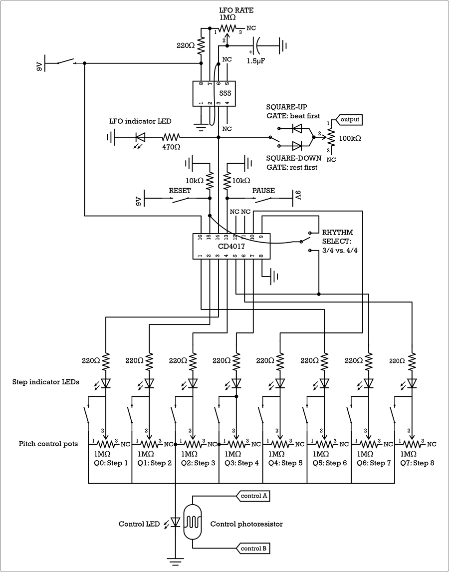
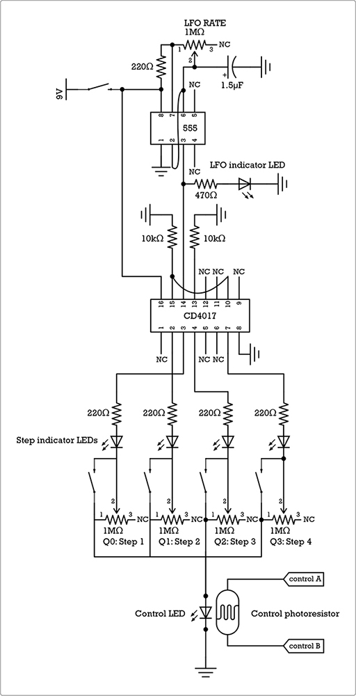
Take a look at the circuit diagram in Figure 16-4, which shows the sequencer portion of the Bleepbox circuit.
FIGURE 16-4: The circuit diagram for the sequencer
The LFO section at the top is the same 555 timer-based circuit that drives the Universal LFO (Project 13). This IC feeds a steady beat to the input of the CD4017 chip. The CD4017 is also called a decade counter: it watches for a signal on its input (pin 14), and every time it detects a beat, it advances its count by turning off the current output and turning on the next output. It starts with its first output—labeled Q0—turned on. When it detects a beat coming from the 555, it turns off Q0 and turns on the second output, labeled Q1. At the next beat, it turns off Q1 and turns on Q2, and so on all the way to Q9, for a total of 10 possible steps before looping back—hence the decade in the IC’s name, although we’ve wired it up to loop back after its eighth step.2 Each step in the count drives an indicator LED wired to a switch and pot that allow you to control the brightness of the indicator LED.
The LED/switch/pot assemblies from each step are then tied together to drive a final control LED that matches the brightness of the currently lit step indicator LED. This final control LED is strapped to a photoresistor: the brightness of the control LED thus determines the resistance of the photoresistor, which in turn controls the pitch of a slightly modified version of the Single-Chip Space Invader Synth. This “LFO Æ decade counter Æ indicator LED Æ pot Æ control LED” scheme allows us to fully automate a sequence, with control over the pitch of each step and the overall tempo of the pattern.
* NOTE: For clarity, Figure 16-4 doesn’t show the schematic for the modified Space Invader Synth. This schematic is in Figure 16-21, and we’ll give it a look when we’re ready to build the synth itself.
As usual, let’s begin the actual build with the hardware. If you’ve never, ever soldered before, this probably isn’t the place to start; try building the Droid Voicebox (Project 6) first. That’s a great first-time soldering project, and it will also familiarize you with ICs. If you just need a soldering refresher, flip to “Soldering” on page 346.
First, we’ll prepare four switches: power, rhythm selector, pause, and reset. We’ll then assemble the eight switch-pot-LED pitch controllers and finish up by building the click-gate control.
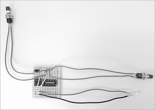
Step 1 Warm up your soldering iron and grab the insulated wire, the 9-volt clip lead, one SPST toggle switch, the SPDT toggle switch, and both pushbutton switches. Cut seven 6-inch wires and one 4-inch wire, and strip and tin both ends of each wire. If need be, strip the ends of the 9-volt clip lead wires (many ship with the leads already stripped and tinned). Now, solder one 6-inch wire to each lug of each pushbutton switch and solder one 6-inch wire to each of the three lugs on the SPDT switch. Then, solder the 4-inch wire to one of the SPST toggle switch terminals—it doesn’t matter which—and finish up by soldering the positive (red) lead from the 9-volt battery clip to the other SPST toggle switch terminal. You now have your power, reset, pause, and rhythm selector switches, as shown in Figure 16-5.
Step 2 Prep the tempo control pot next. Cut, strip, and tin two 6-inch lengths of insulated wire. Take one of your 1M ohm pots and solder one wire to lug 1 and the other to lug 2 (see Figure 16-6).
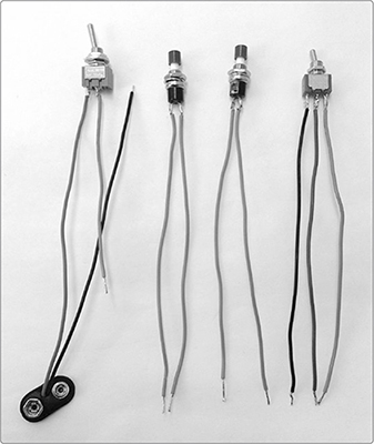
FIGURE 16-5: From left to right: power, reset, pause, and rhythm selector switches
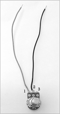
FIGURE 16-6: The prepared tempo control pot
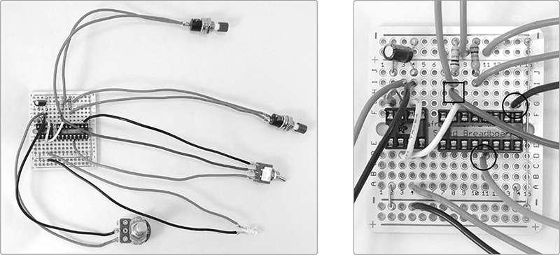
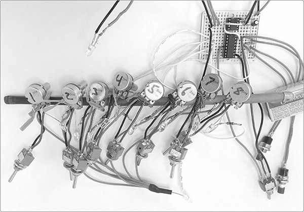
Step 3 Prep the eight step controllers. Use your multimeter—or, barring that, a simple continuity tester circuit, like the “Super-Basic Continuity Tester” on page 357—to make sure all of your eight remaining SPST toggle switches are turned off. In the off position, the switch leans toward one lug; for example, in Figure 16-7, my switch is turned off and leaning toward the left lug. Let’s call this left lug—the one the switch is leaning toward when turned off—Lug A. On each switch, mark Lug A with a dot so you can easily orient the switches when building each step controller. (You’re going to be really annoyed later if you discover that you installed some switches backward.) The dot-free lug is now Lug B. Use your marker to number your eight 1M ohm pots 1 through 8, and you’re ready to start soldering.
Step 4 Build your first pitch controller. Gather the 1M ohm pot you labeled 1, an LED, a 220 ohm resistor, and an SPST toggle switch. Cut two 6-inch lengths of insulated wire and two 2-inch lengths of insulated wire. Strip and tin both ends of each wire.
* NOTE: In Figure 16-7, I’ve used four different colored wires (from left to right: red, black, green, and white). This minimizes the likelihood of wiring connections incorrectly. I strongly recommend using a similar color-coding scheme.
Step 5 Solder one 2-inch wire to each toggle switch lug and solder one 6-inch wire to one leg of the 220 ohm resistor (that’s the white wire in Figure 16-7). Solder the other leg of this resistor to the positive leg of the LED, which is the longer one, opposite the flat area on the side of the LED body. Twist together the remaining (negative) LED leg and the 2-inch wire attached to switch Lug B. Solder this pair to pot lug 2, as shown in Figure 16-7. Then, twist the 2-inch wire attached to switch Lug A with the remaining 6-inch wire. Finally, solder this pair to lug 1 on the pot. Ta-da! Your first step controller is complete. Repeat seven times for a total of eight assemblies.
Step 6 Once you’ve finished all eight pitch controllers, gather the leads connected to lug 1 of each pot and twist the ends together into a big bundle, using pliers if necessary. Solder that bundle to the longer, positive leg of the final LED—which will serve as the optocoupler’s control LED. Then, cut, strip, and tin another 6-inch length of insulated wire and solder it to the negative leg of this LED (the shorter leg nearest the flat area on the LED body). Consider reinforcing the eight-wire LED connection with some electrical tape or shrink tube, as I have, to prevent short circuits. Figure 16-8 shows the finished 8-step controller assembly.
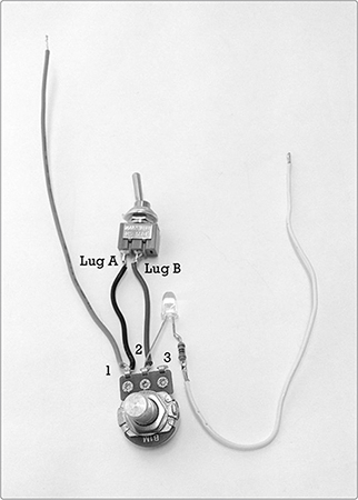
FIGURE 16-7: A single pitch controller. Contrasting wire makes it easier to keep the connections straight.
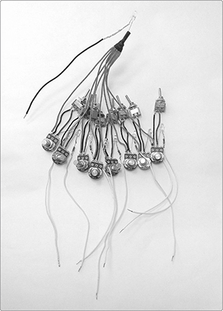
FIGURE 16-8: The finished bundle of pitch controllers connected to the control LED
Step 7 Next, build the click-gate control. Gather your on-off-on SPDT switch, two diodes, and the 100k ohm pot. Cut, strip, and tin two 6-inch lengths of insulated wire. Solder one to lug 1 on the 100k ohm pot. Solder the other wire to the center terminal on the SPDT switch. Pick one of the switch’s two edge terminals—it doesn’t matter which—dub this Terminal A, and mark it with a dot of marker or some correction fluid.
Step 8 Find the black stripe on each diode, as shown in Figure 16-9 (left). The negative diode leg is the one closest to that stripe. Keeping this in mind, solder the positive leg of one diode to Terminal A on your on-off-on SPDT switch. Solder the negative leg of the other diode to the remaining switch terminal. Twist together the free legs on the two diodes and solder them to the middle lug of the 100k ohm pot.
When the switch is leaning toward Terminal A, the click gate is in square-up mode and will accentuate the beginning of each step. When the switch is leaning the other way, the click gate is in square-down mode, accentuating the latter half of each step. When the switch is in the middle, the click gate is disengaged. Set this assembly aside with all the other hardware and get ready to stuff your circuit board.
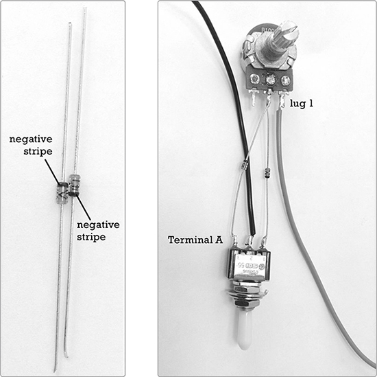
FIGURE 16-9: The completed click-gate control assembly
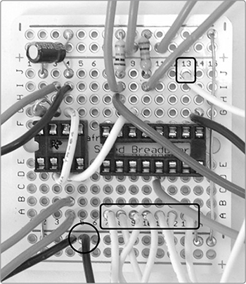
After all the measuring, stripping, twisting, soldering, and repeating you just did, building the PCB will feel like a breezy afternoon stroll. As in earlier projects, we’ll refer to solder pads using the number-letter coordinates etched on the topside of the PCB. For example, the hole farthest to the left directly above the central divide is called 1F.
Step 9 First, mount the IC sockets so that both straddle the PCB’s center divide, as shown in Figure 16-10. The 8-pin socket runs from 2F to 5F above the divide and 2E to 5E below. Leave one column open and then place the 16-pin socket from 7F to 14F and 7E to 14E. If your sockets have notches like those in Figure 16-10, place the notches to the left; that’s just good form. Bend out the top left and bottom right legs on both sockets to hold them in place on the PCB. Then flip the board and solder all the pins to their solder pads. Take care not to create solder bridges between any adjacent pins.
Step 10 Now, add the jumpers shown in Figure 16-11. There are seven: two insulated flyovers and five bare bus connections. Start with the flyovers. Cut two 1 1/2-inch lengths of insulated wire. Use solid core insulated wire if you have it; otherwise, use stranded wire. Strip both ends of each wire, tin them if your wire is stranded, and then run one wire from 3D to 4G over the 8-pin socket, connecting its pin 2 to its pin 6. Run the other wire from 4D to 9G, connecting pin 3 on the 8-pin socket to pin 14 on the 16-pin socket. Solder all four ends of these two wires now.
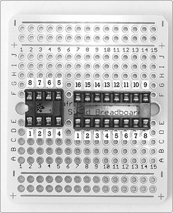
FIGURE 16-10: The IC sockets are in place. Pins are numbered counterclockwise from the lower-left pin of each socket.

FIGURE 16-11: The seven jumpers on your Bleepbox circuit board
Step 11 Snip four 3/4-inch lengths of bare bus wire. Bend each into a flat bottomed U. Run wires from 2A and 14A to the lower ground rail at the bottom of the PCB. This is the row of holes just below the blue line with the negative signs. Run two more jumpers from 2J and 7J to the power rail at the top of the PCB; that’s the row of holes just above the red line with the plus signs. Solder all four of these wires now.
Step 12 For the final jumper, cut a 2 1/4-inch length of bare bus wire and run it down column 15 at the right edge of the PCB from the upper ground (the topmost row of holes) to the lower ground. Solder this wire, and your jumpers are done.
Step 13 Place the three board-mounted resistors, which are two 10k ohm resistors (brown-black-orange stripes) and a 220 ohm resistor (red-red-brown stripes). Bend the 220 ohm resistor into a tight V and mount it from 2G to 3G to connect pins 7 and 8 on the 555 timer. Bend the two 10k ohm resistors into flat-bottomed Us. Run one from 8J to the upper ground rail (the row of holes at the top of the board) and the other from 10J to the upper ground rail. Solder all three resistors, as shown in Figure 16-12.
Step 14 Now for the 1.5 μF electrolytic cap, which connects pin 5 on the 8-pin socket to the ground. Electrolytic caps are polarized, so start by identifying the negative leg, which is aligned with the stripe on the cap’s body. Run this negative leg to the top ground rail and the positive leg to pad 4J (see Figure 16-13). Solder both legs.
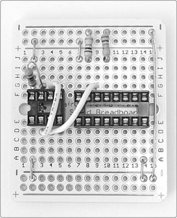
FIGURE 16-12: Placement of the three board-mounted fixed resistors

FIGURE 16-13: Adding the 1.5 μF electrolytic cap
Step 15 Next, add the indicator LED. Cut, strip, and tin two 6-inch lengths of insulated wire. Dig out your final LED and the 470 ohm resistor (yellow-violet-brown stripes). Solder the resistor to the positive LED lead. Then, solder one insulated wire to the open resistor lead and the other wire to the negative LED lead. Run the positive lead, which is attached to the resistor, to pad 4A and the negative LED lead to the lower ground rail at the hole immediately below 4A (see Figure 16-14).
* NOTE: If your enclosure has a clear or translucent top, you can get a pretty neat effect if you skip the insulated leads here and instead solder the indicator LED—with its resistor—directly to the board. This light blinks on and off with each clock cycle of the 555 timer. Mounted underneath a translucent top, it will make your sequencer appear to have a throbbing red heartbeat. Trés chic!
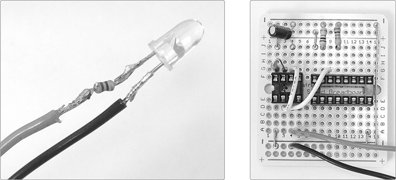
FIGURE 16-14: Detail of the indicator LED with resistor (left). Close-up of the PCB at this stage (right). Note that the two wires near the bottom of the PCB go to the LED.
Now it’s time to install all the hardware from the first few steps. We’ll start with the pause and reset pushbuttons you built in Step 1. These switches send voltage to pin 13 or 15 of the CD4017, respectively, in order to force the chip either to hold at its current step, thereby pausing the sequence, or to jump back to its first step, thereby resetting the sequence.
Step 16 Take one pushbutton switch—it doesn’t matter which—and connect either of its leads to pad 10I on the PCB. Run the switch’s other lead to the power rail at column 11, as shown in Figure 16-15 and in detail in Figure 16-16 (right). Solder both wires. Take the other switch and connect one lead to pad 8I and the other lead to the power rail at column 9. Solder both of these.
Step 17 Now, install the tempo control. Take the only 1M ohm pot left—the one you added leads to in Step 2. Connect the lug 1 lead to pad 3I and the lug 2 lead to 4I. Solder both leads and compare your progress to Figure 16-16.
FIGURE 16-15: Installing the pause and reset buttons
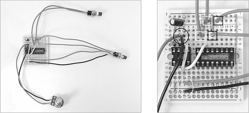
FIGURE 16-16: The tempo control is installed. Detail on the right shows the tempo control pot connections in a black circle, the indicator LED leads in a white circle, the pause button wires in black squares, and the reset button connections in white squares.
Step 18 Install the rhythm selector switch, which is the on-on SPDT switch with three leads. Run the center-lug lead to pad 8H, one side lead—it doesn’t matter which—to 14G, and the final lead to 11D (see Figure 16-17). Solder it all now.
FIGURE 16-17: The rhythm selector is in place. In the detail on the right, the center-lug connection is squared and the other two lugs circled.
Step 19 Install the click-gate control, which is the center-off SPDT switch with the diodes and 100k ohm pot wired to it. Run the lead from the center lug of the switch to pad 4B and solder it. You’ll solder the other wire on this assembly—the insulated lead dangling from lug 1 of the 100k ohm pot—to the output jack after we build the modified Space Invader Synth.
Step 20 Finally, install your 8-step controller bundle—that knot of resistors, LEDs, switches, and wires we built in Steps 3 through 6. There should be eight free wires, each connected to one of the numbered pots via a resistor and LED (see the white wires in Figure 16-18). We’re going to connect these to the PCB in order and solder each immediately so that it doesn’t escape. The lead attached to pot 1 goes to pad 9A, pot 2 to pad 8A, pot 3 to 10A, pot 4 to 13A, pot 5 to 13J, pot 6 to 7A, pot 7 to 11A, and pot 8 to 12A. Figure 16-18 identifies which wire goes where and shows a picture of the PCB at this stage. To finish the pitch-control bundle, run the single open wire on the shared pitch-control LED—which is that LED’s ground—to the lower ground rail at the foot of column 5.
Step 21 Wire the PCB for power. Adding power is super easy: run the negative (black) wire on your 9-volt snap-on connector to the upper ground at the upper-left corner of the board (see Figure 16-19). Run the open wire on the power switch to the power rail in the hole immediately below this.
Step 22 Place your ICs into the sockets. The little 555 timer goes in the 8-pin socket, while the larger CD4017 goes in the 16-pin socket. Push your flyover jumpers out of the way or sneak the ICs beneath them. Both ICs should be positioned with their orientation marking—be it a dot, a divot, or a stripe—to the left, as shown in Figure 16-19.
IC output |
Pot # |
PCB solder point |
Q0 |
Pot 1 |
9A |
Q1 |
Pot 2 |
8A |
Q2 |
Pot 3 |
10A |
Q3 |
Pot 4 |
13A |
Q4 |
Pot 5 |
13J |
Q5 |
Pot 6 |
7A |
Q6 |
Pot 7 |
11A |
Q7 |
Pot 8 |
12A |
FIGURE 16-18: A wiring chart for the step controllers and a picture of the PCB thus far. The wires connecting to each step controller are white. The black-wired ground connection for the shared control LED is circled, and the step controller wires are boxed.
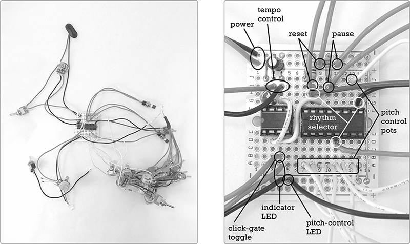
FIGURE 16-19: The finished sequencer circuit (left) with a labeled detail of the PCB (right)
Attach a fresh 9-volt battery and power up your sequencer. Turn the tempo control—the 1M ohm pot wired directly to the board, with no switches or extra components—to its midpoint. Set all the other pots fully counterclockwise and turn all the switches in the pitch-control bundle on so they lean away from Lug A, which you marked in Step 3.
Is the indicator LED blinking? This is the LED that connects directly to the 555 timer at pad 4A. (Other LEDs might also blink, but we’ll get to them in a bit.) If the indicator LED isn’t blinking, flip the power switch and check again. If you still get no response, check that your battery is fresh and look for shorts on your PCB and hardware, especially around the 555 timer, the power switch, and the tempo control pot. Eliminate any short circuits: separate uninsulated wires that are brushing against each other, flick away loose scraps of wire or flakes of solder, and reheat sloppy joints and solder points to smooth them. (The solder should naturally flow to the warmer joint.) If a solder bridge is especially stubborn or there’s just too much solder glumped to a joint, you may need to desolder and redo the connection.
* NOTE: If you’re unsure how to desolder, see “Desoldering” on page 349.
Once the indicator LED blinks, run the tempo control clockwise and counterclockwise. The blinking should speed up as you go clockwise until it becomes a blur or the LED is constantly illuminated, and it should slow as you go counterclockwise to about 50 bpm. If it does the opposite, it just means you wired the pot backward in Step 2. You can either swap the leads by transferring the side lead to the other side or leave them alone and use the knob backward.
Once the tempo control and its indicator LED check out, set the tempo control back to its midrange and turn your attention to the step indicators, which are the eight LEDs wired to the pitch control bundle. They should illuminate brightly and steadily one at a time. The blink rate of the step indicator LEDs is twice as long as the tempo rate LED. That is, each step’s LED should stay illuminated for a full on-off cycle of the tempo rate LED. It will then blink off as the next step blinks on. The common control LED, connected to all eight red step control leads, should stay lit more or less steadily.
* NOTE: The blink of each step indicator LED—and the pitch control LED they share—may have a two-tone flavor, whereby it’s slightly brighter while the tempo rate LED is on and slightly dimmer when the tempo rate LED is off. That’s normal and perfectly acceptable. In fact, it will ultimately lend a little extra color to your synth’s voice.
If any of the steps aren’t lighting up, look again for shorts. A solder bridge or stray fleck of metal on the PCB might be the problem, but the hardware is a much more likely culprit. These LEDs have a tendency to brush up against each other when not secured, and that creates short circuits. Consider temporarily mounting the switches and LEDs on a piece of cardboard or tying them to a chopstick to keep the wires unsnarled and save your sanity while troubleshooting (see Figure 16-20).
FIGURE 16-20: LEDs and switches temporarily mounted on a chopstick to aid troubleshooting. I used kitchen twist ties to hold the wires and pots to the chopstick because they’re insulated and easy to attach one-handed—and my kitchen junk drawer is crammed with them.
Similarly, if two or more step indicator LEDs blink simultaneously, that might be due to a short on the PCB, but it’s more likely due to the legs of neighboring LEDs touching. Consider temporarily mounting the LEDs on something to prevent leads from brushing against each other. If all but two of the steps are lighting up, the rhythm selector is probably just set to 3/4 instead of 4/4; try flipping the stand-alone on-on SPDT switch. Now each pot’s indicator LED should light up in order, from 1 to 8. If they light out of order, you just swapped a wire in Step 20. No harm done: renumber the pots so that they match the order the LEDs illuminate and move along.
Next, check the rhythm selector switch. In one position, all eight LEDs should light up before the sequence loops back to the first step. In the other position, only LEDs 1 through 6 should light before the sequence starts over.
If the rhythm selector checks out, test the overdrive mute switches and pitch pots. Flick the mute switches off so the toggles all lean toward Lug A. The step indicator LEDs should now all be either dark or very dim. Test each pot, checking to be sure that you can set the brightness of the LED for each step; the light should get brighter as you turn clockwise (turning the tempo way down will probably make this easier). Each pot controls the individual brightness of its indicator LED and the brightness of the control LED that they all share. The control LED should shift in brightness to match the brightness of the currently illuminated indicator LED, rather than blinking on and off. Is that happening? If not, then short circuits, especially between those dang LEDs, are probably the cause. And if the LEDs and pots are performing as described? Perfect! Move on to the final test: pause and reset.
The pause button is the one with a lead going to solder pad 10I. Push and hold this button. The current step indicator LED should stay lit, even as the tempo rate LED keeps blinking. Release the button to resume the sequence. Now, press and release the reset button wired to 8I on the PCB. Every time you hit this, the sequence should jump back to LED #1.
When your sequencer circuit passes inspection, you’re ready to put together the synth.
Right now you’ve got a sequencer that doesn’t control anything other than a row of blinking lights. That’s kinda fun, but something that controls a row of blinking lights and makes a rad noise will be much, much more fun. A modified version of the Single-Chip Space Invader Synth (Project 15) will be the Bleepbox’s voice. Let’s build this now, using the modified parts list from the beginning of this project, the circuit diagram shown in Figure 16-21, and the instructions that follow.
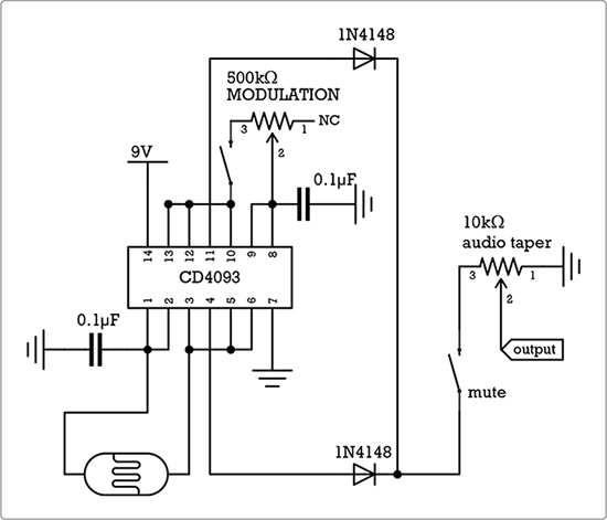
FIGURE 16-21: The circuit diagram for the modified Single-Chip Space Invader Synth
Step 23 Flip to Project 15 and, starting with Step 1, build the synth with the following modifications:
a. Omit the power supply—the switch, 9-volt battery clip, and LED power indicator. Don’t build it in Step 1 or install it in Step 13. Instead, cut, strip, and tin two 6-inch lengths of insulated wire. For clarity, I’ve used red and black wires. Run one of these wires (I’ve used red) to pad 3 on the synth PCB. Run the other wire (I’ve used black) to the synth’s lower ground rail, at the foot of column 13 (see Figure 16-22). We’ll connect these to the Bleepbox sequencer PCB’s power and ground rails in a few steps.
b. Omit the pitch control pot. Skip the 100k ohm pot in Step 2 and ignore all references to it thereafter; it’s dead to us.
c. Add an SPST toggle switch to the mod pot. In Step 2, cut the lead attached to lug 3 of the 500k ohm pot in half, strip and tin both ends, and solder one end to each lug on the SPST toggle switch.
d. Omit the trigger button. Don’t build it in Step 3 and ignore its mention from then on.
e. Replace the 100k ohm pitch control pot in Step 11 with a photoresistor-based pitch controller. Cut, strip, and tin two 6-inch insulated wires. Solder one wire to each leg of the photoresistor. Solder one of these leads to pad 3A on the Space Invader Synth’s PCB and the other to pad 10A.
Your Bleepbox-ready Space Invader Synth is good to go! Figure 16-22 shows the results.
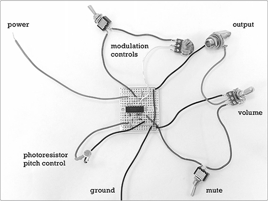
FIGURE 16-22: The modified Space Invader Synth circuit, ready to be grafted to its new master
The synth voice will be both powered and controlled by the sequencer circuit. Let’s wire them up now.
Step 24 Connect the free end of the insulated wire connected to pad 3G on the Space Invader Synth PCB to the power rail on the sequencer PCB at column 13 (see Figure 16-23). Connect the black ground wire on the synth PCB’s lower ground rail at column 13 to the sequencer’s upper ground rail at column 13, above the power connection you just soldered. Solder these now. Finally, solder the remaining lead from the click-gate controller to the tip on the Space Invader Synth’s output jack—that’s the positive lug, not the ground.
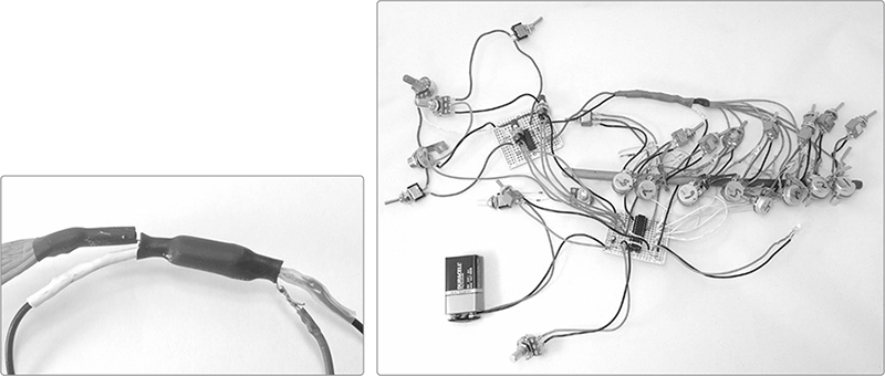
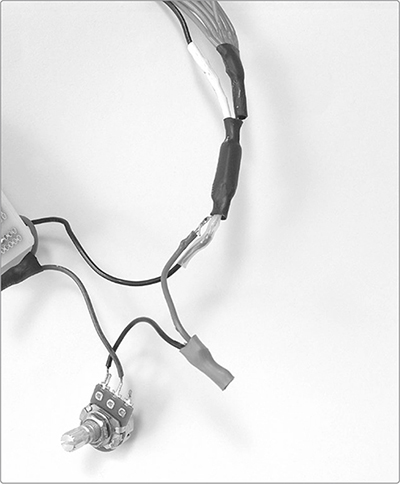
FIGURE 16-23: A close-up of the optocoupler (left). I sealed mine with black heat-shrink tube instead of tape; both work fine. The finished guts of the entire Bleepbox 8-Step Analog Sequencer (right). I added an extra reinforcing wrap of tape to the optocoupler prior to installing the guts in their enclosure.
Step 25 To finish the Bleepbox, we need to bind together the common control LED that’s wired to all eight step controllers with the photoresistor on the synth, forming an optocoupler. We built this same style of optocoupler for the Universal LFO (Project 13); the three steps are illustrated in Figure 13-13 on page 229. Place the common control LED and the photoresistor snout to snout, as shown in Figure 13-13, and wrap them in duct tape, making sure to seal them completely.
Your Bleepbox is complete and ready to test!
Set the volume pot, the tempo pot, and all of the pitch pots to halfway. Turn the click-gate depth pot fully clockwise and turn the mod rate pot fully counterclockwise. All of the overdrive mute switches should be off—that is, leaning toward Lug A and, therefore, not engaged—and the output shouldn’t be muted. Set the rhythm selector to 4/4 and the click-gate switch to its middle position so neither gate option is engaged. Connect your 9-volt battery, plug in your amp, and then power up the amp and the Bleepbox.
The tempo rate LED should blink at about 60 bpm, and you should hear a relatively steady tone, varying only slightly from step to step. You should also see each step LED light up in sequence. Don’t worry if they’re fairly dim; that’s normal.
Flick all of the overdrive mute switches on. Now there should be no droning tone, and each LED should light in sequence at maximum brightness. Try the tempo control pot; it should still make both the tempo rate LED and the individual step LEDs blink faster as you go clockwise and then slower as you go counterclockwise. At full clockwise, all of the LEDs will probably appear to be continuously lit. You may also hear a sudden, quiet squeal when you get the tempo control pot to its extreme clockwise position; that’s normal. At full counterclockwise, the blink rate may be downright glacial, especially if your 9-volt is wearing down from all this testing.
Return the tempo control pot to halfway and then flick the rhythm selector switch from 4/4 to 3/4. Instead of each of the eight steps lighting in sequence, the Bleepbox should now light only the first six steps before starting over at Step 1. Flip the selector back to 4/4.
Let’s test the click-gate function. Flick the switch so it’s leaning toward Terminal A, which you marked earlier. You should now hear two clicks per step, corresponding to the light and dark period of the tempo rate LED. This is square-up mode.
When you flick to the other position on the click-gate switch, you should hear two louder clicks in a more distinct alternating “one-two” pattern. This is the square-down mode. Turning the click-gate pot counterclockwise should make these clicks quieter, but you should still hear them even when the pot is fully counterclockwise. Return the click-gate switch to its center position, and you should be back to virtual silence, with maybe just a very distant clicking.
Check the pause and reset buttons. Hit pause to make the sequencer hold on the current step; hit reset to make it hop back to the first step. The tempo rate LED should keep beating steadily throughout this. You might find that these buttons behave a touch erratically, especially if you press them quickly or right on top of the tempo rate LED blinking on or off. This is to be expected.
* NOTE: Erratic button behavior is caused by contact bounce. A simple switch contains two springy copper contacts, and when you close the switch, the contacts don’t snap together cleanly. Instead, they smack against each other, creating a flurry of electronic pulses before they settle in place. In most situations—like when flicking a light switch—you don’t notice contact bounce because the chatter is fast and tiny while the overall voltage of the system is large. But in logic circuits like this, contact bounce can confuse the chip. If you want to get rid of this, you can build a debounce circuit; just google bounceless switch or debounce circuit for examples. I didn’t debounce for this project because I like the pseudo-randomness.
Now, test the modulation oscillator controlled by the mod rate knob and mod switch. Twist the knob clockwise, and you should hear a high-pitched, buzzy square-wave tone that gets lower as you continue clockwise. A slight shift in the tonal color as the tempo rate LED clicks on and off is normal. If you flick the toggle switch, the mod square wave should be muted. Once tested, flick the toggle switch back and twist its knob fully counterclockwise.
Finally, disengage all of the overdrive mutes. You might want to turn the output volume down here. Use the pause button to pause on a few different steps and then change the pitch using that step’s pitch-control pot. Turning the pot clockwise should make the pitch higher, while turning counterclockwise should make it lower.
Release the pause button. Turn the mod oscillator’s knob clockwise, and you should hear the mod oscillator modifying each step’s pitch. Flick the mod switch off, and you should just hear the square-wave pitch of each step. Turn the mod back on, and you’re back to a richly textured dual-oscillator voice. Flick the output mute switch, and all should go quiet.
Because this project is so complex, expect some hiccups. If the sequencer was working as of Step 22, then any gremlins you come across now are probably related to the new Single-Chip Space Invader Synth board or to the places that the two boards connect. It’s also possible that you inadvertently created a short circuit in the sequencer circuit while wiring it all up.
If you do find problems, they’ll almost invariably be simple. Check for dead batteries, bum switches, or short circuits, which are usually LEDs brushing against each other or the body of a pot. Persevere, and you shall overcome.
When you know the Bleepbox guts work, you’re ready to package them up. Selecting and customizing an enclosure is totally a matter of personal preference, but in a build with so many wires and so much hardware, it can be bit of a bear. Here are a few tips as well as some process shots of my enclosure:
Ask yourself what looks good, what will be most playable, and what will work best with the circuit. Figure 16-24 shows a cigar box that’s about 9 × 7 inches and just over 1/2 inch deep. In my opinion, these are ideal dimensions: the enclosure is portable, sits well on a table or lap, and has plenty of room to house everything without risking shorts and pinched wires. Plus, you can place the controls close enough together that it’s easy to play live.
Sketch your button layout and then mock it up using some spare parts or paper cutouts. When you’re happy, sketch the layout on the inside of the enclosure before you start drilling (see Figure 16-24). If you drill from the inside, your holes will be cleaner, and the exterior top of the Bleepbox will be unmarred. But there’s a downside. When you sketch your layout on the underside of the panel like this, you’re forced to pull a Ginger Rogers: you’ve gotta do everything Fred Astaire does, but backward and in high heels. Make a sketch in advance, double-check everything, and constantly ask yourself, “Am I about to accidentally drill this whole layout as a mirror image or upside down?”
Space your hardware out. You want parts grouped conveniently, but not so close that they create short circuits or are impossible to install. I placed the step-control hardware 1 inch apart horizontally, with about 1 inch between the pot and LED and 1/2 inch between the LED and switch. Most of the hardware is similarly laid out in inch multiples in rough columns and rows. It’s a tidy look, and I recommend it.
Use the right-sized bit. For the hardware in the parts list, use a 3/8-inch drill bit for the output jack, a 5/16-inch bit for the pushbutton switches and pots, a 1/4-inch bit for the toggle switches, and a 3/16-inch bit for the LEDs. These dimensions should give nice, snug fits without a lot of tedious reaming and filing.
Be careful with switch orientation! It will get really confusing if some of your overdrive mutes engage when flicked to the left and others engage when flicked to the right. It’s also much more intuitive to have the click gate in square-up mode when flipped up and in square-down mode when flipped down. This is all a matter of personal preference, but like twisting clockwise to speed up or increase pitch, it just feels right.
Consider your labeling options. In Figure 16-1, I fully embraced the junkyard aesthetic: I used extra fine point marker on swipes of correction fluid. On the other end of the spectrum, you could use a slick metal enclosure and print the text on self-adhesive labels. Want that 1980s analog synth/drum machine vibe? Search online for the Orbitron and TR-909 fonts; these are free lookalikes inspired by the typefaces used by Roland, Kawai, Korg, Alesis, and their ilk. Whatever you decide, make your life easier and label those knobs and switches.
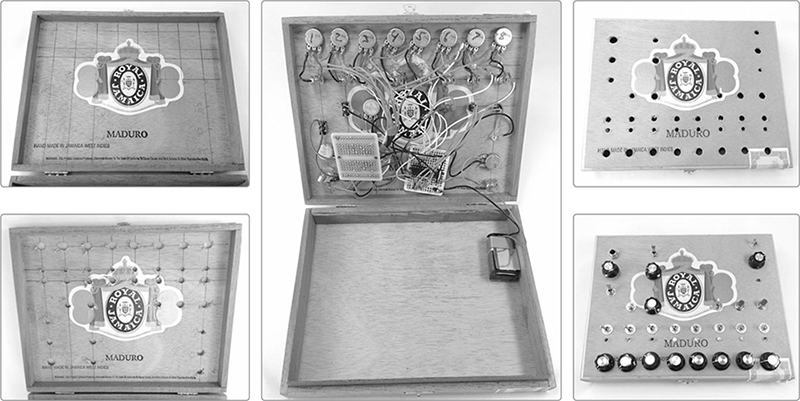
FIGURE 16-24: A few process shots of the enclosure build
Let’s program a sequence together. This’ll give us an opportunity to work through all the features of the Bleepbox. Once you’ve heard them in action, opportunities for improvisation will begin to present themselves.
For starters, prepare the synth. Make sure it has a fresh 9-volt battery and is powered down. Then, program it as follows.
Control |
Setting |
Control |
Setting |
Volume |
75% or higher |
Step 1 |
9 o’clock |
Output mute |
Off (unmuted) |
Step 2 |
12 o’clock |
Modulation |
On, 50% |
Step 3 |
9 o’clock |
Tempo |
75% |
Step 4 |
12 o’clock |
Rhythm selector |
4/4 |
Step 5–8 |
3 o’clock |
Click-gate |
Middle position (neither gate option engaged), with pot fully clockwise |
All overdrive mutes |
Off |
Set your amp to about 25 percent, plug in the synth, power up the amp, and then power up the synth. The sequencer should play the following programmed sequence: an alternating high and low pitch, followed by a more-or-less continuous lower pitch—something like be-bop-be-bop-ba-ah-ah-ah. You’ll note that the sequence plays in a portamento style, sliding between notes instead of crisply jumping from one to the next. This is a consequence of the photoresistor-based analog pitch controller. The effect gets really neat when it moves from a fairly low tone, such as step 8, to a high one, such as step 1. You’ll hear a fast, pronounced slide into the new note.
The overdrive mute takes full advantage of this portamento playing style. Engage the overdrive mutes in steps 5 through 8. When your sequencer hits step 5, the pitch should drop out, muting the last four steps of the sequence, but when step 8 wraps back to step 1, you should get a big squealing slide to the step 1 note.
To deemphasize this portamento effect and emphasize the rhythmic aspects of the automated sequence, engage the click-gate control in square-up mode. You should hear a click twice per step, corresponding with the off and on blinks of the tempo rate LED.3 Note that the first half of each step is significantly louder than the second half. If you turn down the click-gate depth knob, you’ll decrease the depth of the effect, making the difference in emphasis between the first and second half of each step less obvious. The click should remain present but will get quieter as you turn down the effect depth.
Switch to square-down mode, crank the click-gate knob to full, and listen for two changes: the click should be less apparent, and each step should start with a rest, bringing the note in on the second half of each step. This greatly deemphasizes the slide between notes and gives your groove a funky backbeat feel. The square-up gate effect can be fairly subtle, while the square-down gate tends to be more emphatic, with a wider variety of variation as you change the depth.
You’ll notice that you still hear the 16th-note clicks even when steps are overdrive muted, with the square-up clicks more emphatic than the square-down clicks. When you engage the output mute, it will silence the square-up clicks, but the square-down clicks will remain audible. This is a really useful trick, as it makes it possible to drop a break into your set—muting all the notes—while keeping the clicks running, maintaining the beat. It’s sort of like having a bass-line synth with a very rudimentary built-in drum machine.
* NOTE: When the square-down gate is engaged and its depth is set to 100 percent, the synth’s voice may leak through the output mute. Turn the click-gate depth back to 90 percent or lower to completely mute the synth voice even as the 16th notes click away.
Flip the click gate back to square-up mode and unmute the output and all the steps. This sequence program has two distinct parts and is designed to be easily cut and looped using the reset and pause buttons. Hit reset just as step 5 is about to come on. You’ll send the sequence back to step 1, looping the be-bop-be-bop section of the sequence. Repeatedly doing this will build tension, which you can then release by letting the sequence run all the way through uninterrupted. You can also build tension with the pause button: pause a specific step, let it hold for a few beats, and then release it. Once you’re comfortable cutting, looping, and building tension, try stuttering the pause and reset buttons, either individually or together, to create random glitch effects and irreproducible improvisational breakdowns.
When you have a feel for your sequencer controls, try tweaking the mod rate knob as the sequence plays or even muting the mod entirely. Explore sounds and textures by adjusting the mod slowly or quickly; zero in on ranges or settings where interesting multitone timbres arise. Tweak a few step pitch knobs. If you do this while a step is active, you can warble or slide the note. If you tweak while the step is inactive, the sequence will seem to slowly evolve. And don’t neglect the power of muting all or some of the steps and then unmuting them as the sequence comes back around. Music is all about establishing patterns, violating them, and then restoring them.4
Finally, switch the rhythm selector to 3/4. You’ll find that the sequence now loops at step 6, instead of going all the way to step 8. This is most immediately recognizable as waltz time—although at the moment, it doesn’t sound that waltzy. Slow the sequence down a touch, set the click gate to square-up mode at 100 percent, and engage the overdrive mutes on the even-numbered steps. Count it out as one-ee-and-ah-two-ee-and-ah-three-ee-and-ah and voilá! You have “The Space Cowboy Waltz,” as arranged for phasers set to stun.
One more nifty trick: your Bleepbox makes a great metronome! Turn off the mod oscillator, turn all eight step controller knobs fully counterclockwise, engage all eight overdrive mutes, mute the output, set the rhythm selector to 4/4, flip the click gate to square-down mode, and set its depth to 100 percent. Turn on the Bleepbox, and you’ll hear a steady pulse of 16th notes. You can break this string of 16th notes into recognizable bars by disengaging the output mute and turning off the overdrive mutes on specific steps. For example, try turning on steps 1 and 5 to get two tones separated by eight clicks, or try turning on steps 1, 3, 5, and 7 for four tones separated by clicks. Adjust the tempo to your liking and play along with the beat. You can even cut the audible tones and clicks entirely (by setting the click gate to its middle position and engaging the output mute) and just use the blinking lights to help you keep time.
We’ve loaded the Bleepbox 8-Step Analog Sequencer with every damn feature we could squeeze out of these chips, so most of the mods offered here are omissions.
If the click-gate controls don’t do anything for you, you can eliminate them with no ill effects; just leave out the paired diodes, SPDT on-off-on switch, and 100k ohm pot. You can similarly skip the pause button, reset button, or rhythm selector without dire consequences. If you omit the rhythm selector, you’ll want to run one extra jumper from 8H to either 11D (for a 6-step sequencer) or 14G (for an 8-step sequencer).
You could likewise reduce this to a simpler and cheaper 4-step sequencer by omitting the rhythm selector and half the pitch-control assemblies. Just wire pin 10 on the CD 4017 chip directly to the pin 15 reset to force the sequence to loop after four steps. Figure 16-25 shows the circuit diagram for this minimal 4-Step Bleepbox.
FIGURE 16-25: The circuit diagram for a 4-Step Bleepbox
Because the Bleepbox uses the same sound circuit as the Single-Chip Space Invader Synth, it also outputs a hot enough signal to drive a set of headphones. Just plug ’em in, as shown in Figure 16-26 (left). Or you can outfit the Bleepbox with its own built-in or detachable monitor speaker, as discussed in the Space Invader Synth’s “Tips, Tricks, and Mods” on page 281. The same speaker selection rules apply. Figure 16-26 (right) shows a Bleepbox sporting the dandelion speaker described in Project 15.
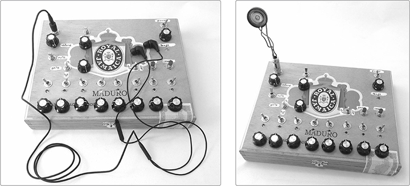
FIGURE 16-26: A Bleepbox kitted out with headphones (left) and a small dandelion speaker (right)
If you really like creating tight 4-step loops, consider swapping the SPDT rhythm selector switch for an SP3T switch, also sometimes written as 1P3T. This style of switch can select among three circuits instead of just two. Such switches are relatively rare and often expensive, but try googling SP3T rotary or SP3T toggle to see if you get lucky. These switches also occasionally turn up in the usually very lowpriced surplus and junk bins at electronics shops. When adding a three-position switch, wire the extra terminal to pin 7 on the CD4017, which will enable 4-step patterns. Label this new setting 4, the old 3/4 as 6, and the old 4/4 as 8. Also, relabel the rhythm selector something like sequence length.
One final mod is to add an extra pot to bend the overall pitch of the synth. Wire the pot in series with the photoresistor side of the optocoupler that connects the sequencer control to the modified Space Invader Synth board (see Figure 16-27).
FIGURE 16-27: A pitch-bend pot installed in a Bleepbox
Clip one of the wires connecting the photoresistor to the synth—it doesn’t matter which. Strip and tin both free ends. Then solder one end to lug 1 of your pot and the other to lug 2. Twisting this new pitch-bend pot counterclockwise will lower the pitch of the entire sequence as it plays. This makes it possible to tweak and warble an entire sequence at once without disrupting the relationship between the notes. Wired in this fashion, the pitch-bend pot affects only the main pitch oscillator, not the mod oscillator. One thing to keep in mind: bending the pitch down like this usually cancels out the overdrive mutes because it drags them down into the audible range.
Finally—and above all else—your finished Bleepbox is a sound circuit; it can be circuit bent just like any commercial music machine or noise-toy. Poke it and prod it. Add body contacts, extra pots, or a Universal LFO wherever and however you deem fit. Take your cues from Circuit Bending for Beginners (Project 7) and start exploring and exploiting.
If you’ve gotten this far, you’re ready to build just about anything thrown your way in books like these:
Handmade Electronic Music: The Art of Hardware Hacking by Nicolas Collins (Routledge, 2009)
Electronic Projects for Musicians (Music Sales America, 1992) and Do-It-Yourself Projects for Guitarists (Backbeat Books, 1995) by Craig Anderton
Getting Started in Electronics by Forrest M. Mims III (Master Publishing, 2003), which includes schematics for “100 Electronic Circuits” in the back
Timer, Op Amp & Optoelectronic Circuits & Projects by Forrest M. Mims III (Master Publishing, 2004)
Anything in the pages of MAKE magazine
Most simple circuits you find online. If you like this book’s projects, google Tim Escobedo circuits or Atari Punk Console5 and go from there.
You’re also ready to begin exploring the world of synth and musical effect kits. Check out these sites:
PAiA (http://paia.com/) offers lots of kits—including full analog monosynths and modular synthesizer systems as well as their venerable Theremax Theremin. More importantly, they sell reasonably priced kits for many of the best projects from Anderton’s Electronic Projects for Musicians. Don’t miss some of the awesomely priced little kits in the website’s “Building Block Kits” section.
Music from Outer Space (http://www.musicfromouterspace.com/) has lots of neat kits; I’ve been sorely tempted by their Noise Toaster and Echo Rockit kits.
The music section of the Maker Shed (http://www.makershed.com/collections/music/) also carries a variety of electronic music kits and is adding more all the time.
Congratulations! You’ve most definitely earned your old-school electronics geek merit badge. Wear it proudly, let your freak flag fly—and go make your own sound now!