When you pump up the volume, you have more sound to work with. A preamplifier boosts your instrument’s volume, allowing a quieter instrument to cut through the mix when it’s being played with louder instruments. This is also handy if you have an instrument-level signal—like the one produced by an electric guitar or by the Playing-Card Pickup (Project 9)—that you want to feed into effects or other gear that expects a hotter line-level input (the sort generated by synths, drum machines, powered mics, and so on).
Even in a stripped-down solo application, a preamp can be your best friend: boosting the volume brings out subtle sounds and tones, lengthens the decay of your notes, and gives you access to a broader dynamic range.
But the Mud-n-Sizzle Preamp doesn’t just boost your signal; a beefy built-in filter lets you shape your tone. At one extreme, you get a muddy, mellow throb; and at the other, you get a sharp sizzle that, at full volume, crests into a warm fuzz tone.
Building this project will also give you practice using a generic printed circuit board (PCB) that has no predefined connections between soldering pads. Learning to run your own traces (connections between components) is a great skill that gives you much more flexibility. Now when you find a neat schematic online, you’ll be able to build the project, even without step-by-step instructions.
Hear the Mud-n-Sizzle Preamp in action in the samples at http://www.nostarch.com/jamband/.
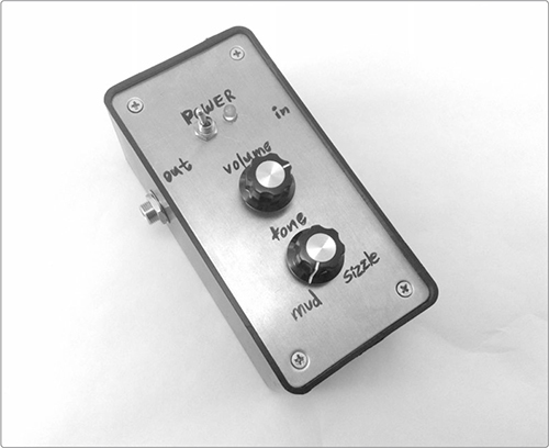
FIGURE 12-1: The finished Mud-n-Sizzle Preamp
Build Time
 Under an hour
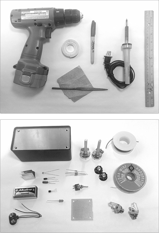
Tools
A standard soldering kit (See page 340.)
A ruler that shows 1/4-inch increments or smaller
A fine-point Sharpie or other permanent marker
An electric drill with bits (You’ll probably need 3/16-inch, 1/4-inch, 5/16-inch, and 3/8-inch bits.)
(Optional) Other tools to work your enclosure (If you’re using a wooden enclosure, you’ll want sandpaper and possibly files to clean up drill holes.)
(Optional) Foam-backed double-sided tape or hardware to mount the circuit in its enclosure
(Optional) A hacksaw for trimming down potentiometers with long shafts
Supplies
A 2N3904 NPN transistor, such as Mouser part #512-2N3904BU
A red LED
A 1.5 μF electrolytic capacitor
A 10 μF electrolytic capacitor
A 0.1 μF capacitor (marked 104)
Two 1M ohm resistors (brown-black-green stripes)
A 10k ohm resistor (brown-black-orange stripes)
A 10 ohm resistor (brown-black-black stripes)
A 470 ohm resistor (yellow-violet-brown stripes)
Two 10k ohm audio potentiometers (These are variable resistors with an audio taper; see “The Gory Details: Audio Taper vs. Linear Taper” on page 327.)
Two control knobs that fit your potentiometers
A 9-volt battery
A 9-volt battery clip
24-gauge insulated hook-up wire (Stranded wire is best here.)
22- or 24-gauge bare bus wire (This is uninsulated solid core wire, which we’ll use to run the ground connection among the potentiometers and jacks.)
Two 1/4-inch mono phone jacks, also called guitar jacks
A pad-per-hole printed circuit board (Figure 12-2 shows an old piece of RadioShack part #276-148, but you can use a 10 hole × 10 hole piece of any generic PCB, which is about 1 square inch. The SparkFun PRT-08811 is a perfect alternative, and the Jameco 105100 is good, too.)
A small SPST toggle switch (You can use Mouser part #108-MS550K, which is shown in Figure 12-2, but any similar switch will work.)
A small, sturdy enclosure (You can buy a suitable project box at many hobby shops, especially those appealing to electronic tinkerers, or you can use something you find around the house or garage. See “On Enclosures” on page 214 for more information.)
(Optional) A 9-volt battery holder clip, such as Digi-Key part #71K-ND or Mouser part #534-071
FIGURE 12-2: Tools and supplies (not shown: hacksaw)
First, peek at the diagram for this circuit, as shown in Figure 12-3. If this schematic means nothing to you, don’t sweat it: that’s why there are illustrated step-by-step instructions.

FIGURE 12-3: The circuit diagram for the Mud-n-Sizzle Preamp
Keep in mind that a circuit diagram shows functional relationships between components; it’s not an image of how the pieces are physically laid out but instead illustrates how the pieces connect. Connections to the ground—that is, the negative battery terminal—are a perfect example: this circuit has quite a few ground connections, each represented by a little triangle made from three parallel lines. Five of these are shown in Figure 12-3, peppered around the circuit. The input and output jacks will also each be grounded, for a total of seven ground connections. The schematic shows ground connections all over the place, but on the physical board, they’re all clustered in the same row.
Now that you’ve seen the circuit, we’ll prep some components, build the circuit, and then put it all together.
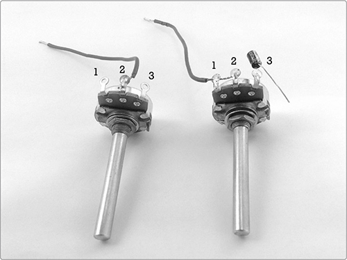
We’ll prepare the potentiometers and jacks first, starting with the volume and tone controls, so you can practice soldering with the components that are the most difficult to damage.
Step 1 While your soldering iron warms up, grab your two 10k ohm potentiometers, or pots, and your marker. Mark the back of one pot with a V (for volume) and the other with a T (for tone).
Step 2 Cut a 4-inch length of insulated wire. Strip about 1/4 inch of insulation off either end and tin each end of the wire. (If this is your first soldering project or if you just need a refresher, see “Soldering” on page 346.) Solder one end of this wire to the V pot’s middle lug, as shown on the left in Figure 12-4, and then set it aside.
Step 3 Cut another 4-inch length of insulated wire. Strip 1/4 inch of insulation from one end and 1/2 inch of insulation from the other. Then tin both ends. Thread the tinned 1/2-inch end of the wire through lugs 1 and 2 of the T potentiometer (see Figure 12-4; we’re talking about the pot on the right). Solder this wire to those lugs.
Step 4 Finally, solder the positive leg of the 1.5 μF electrolytic capacitor to lug 3 of the T pot. Most electrolytic caps (including this one) are polarized, which means they have a positive and negative leg. The negative leg is marked with a stripe running down the capacitor’s body, so in this case you’ll want to solder the stripeless leg to lug 3 (see Figure 12-4, right).
FIGURE 12-4: The finished volume control (left) and tone control (right)
* NOTE: Long potentiometer shafts—like the ones shown here—are a pain to work into most small enclosures. If you have long-shafted pots like these, now is a good time to shorten them. For details, see “Resistors: Fixed and Variable” on page 325.
Next, we’ll build the power supply, beginning with the indicator LED.
Step 5 Solder the 470 ohm resistor (marked with yellow-violet-brown stripes) to the positive LED lead, which is the longer one. The shorter, negative lead is the one closest to the flat section of the LED’s mostly round casing. The finished indicator LED is shown on the left of Figure 12-5.
Step 6 Now for the power switch itself. Start by tinning both lugs of your toggle switch. Next, cut one 5-inch length of insulated wire and strip and tin the last 1/4 inch of each end. Then strip and tin the final 1/4 inch of both the red and black leads attached to the 9-volt battery clip. Solder the positive (red) lead to one lug of your switch. To the remaining lug, solder both the 5-inch length of wire and the resistor side of the indicator LED assembly (see Figure 12-5, right).
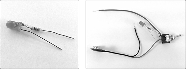
FIGURE 12-5: The completed power supply (detail of the LED assembly on the left)
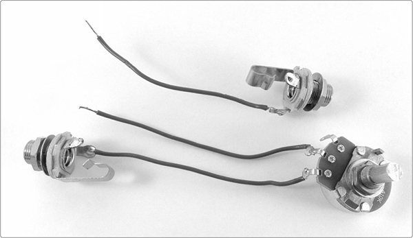
Finally, prep the input and output jacks, which are the last pieces of hardware.
Step 7 Cut a pair of 4-inch wires, strip the ends, and tin them. Solder one wire to the tip lug of each jack, as illustrated at the top of Figure 12-6. (If you’re not sure which lug is which, see “Quarter-Inch Phone Plugs and Jacks” on page 337 for an illustrated introduction to 1/4-inch jacks.) That’s all for the output jack, so put one jack aside.
Step 8 Grab the volume control pot (that’s the one marked with a V) and the remaining jack. Solder the lead you added to the jack in Step 7 to the first lug on the volume control pot, as shown at the bottom of Figure 12-6.
FIGURE 12-6: The prepared jacks (output jack at the top, input jack at the bottom)
For now, set aside the tone control pot, the power switch with LED indicator, and both jacks. We’ll wire these all up at the end, once we’ve mounted all the components on the PCB.
Let’s begin building the circuit itself, starting with the transistor.
Step 9 Mount the transistor in your PCB. Hold the PCB so that the copper pads face away from you and slide the legs of the transistor through three vertical holes at the middle of the board. You want the transistor’s flat face pointing right (see Figure 12-7).
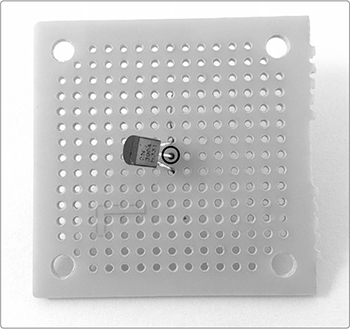
FIGURE 12-7: The transistor is in place, and the leg you solder in Step 10 is circled.
* NOTE: If you’re using a 10 hole × 10 hole scrap of PCB (the smallest you can get away with here), then make sure your transistor is positioned so that there are at least three open rows of holes above the transistor, four rows below the transistor, four open columns of holes to the right, and five open columns to the left.
Step 10 Once the transistor is in place, bend its upper leg up and its lower leg down to hold it in place. Then solder the middle leg (also called the base) to the solder pad on the underside of the PCB, but don’t clip the lead yet. For the remainder of this project, clip leads only when specifically told to do so.
Step 11 Bend one of your 1M ohm resistors (brown-black-green stripes) into a V shape, as shown in Figure 12-8 (left). Then, slide one lead into the hole immediately to the left of the transistor’s middle leg and the other lead into the first hole immediately above the transistor’s upper leg (also called its collector), as shown in Figure 12-8 (right). Once you insert the resistor, bend its upper leg to hold it in place and solder the leg closest to the transistor’s middle leg to its pad.
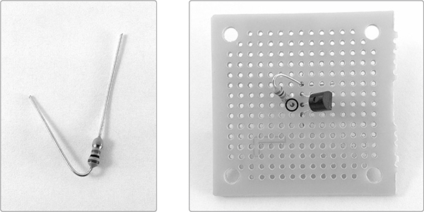
FIGURE 12-8: The first 1M ohm resistor is in place, and the solder point is circled.
Step 12 Bend your other 1M ohm resistor into a U shape, as shown in Figure 12-9 (left). Mount it on the PCB vertically so that one lead is in the first open hole to the left of the transistor’s middle leg and the other lead is five rows down. When your resistor is in place, solder the top leg to its pad, as indicated in Figure 12-9 (right), but don’t solder the bottom leg for now.
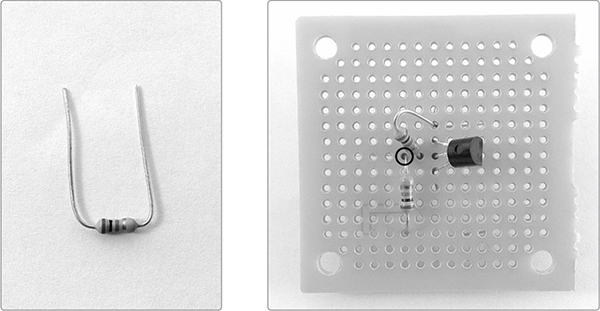
FIGURE 12-9: The resistors are installed, and the solder point is highlighted.
Step 13 Insert the 0.1 μF input capacitor into the PCB. Place one lead in the first open hole to the left of the transistor’s middle leg. Insert the other lead two holes to the left so that there’s an empty hole between the two legs (see Figure 12-10). Solder the rightmost lead to its pad. The middle PCB row should now have the following, counting from the right: the transistor’s middle leg, the bottom lead from the first brown-green-black resistor, the top lead from the second brown-green-black resistor, and both input capacitor legs.
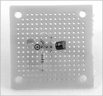
FIGURE 12-10: The placement of the 0.1 μF input capacitor
When you use a PCB without predefined traces, you have to connect the components by soldering bridges between pads on the underside of the PCB so that a current can run through the metal to each component. This requires a bit of practice, so don’t worry if your first try looks ugly. Ugly metal conducts just as well as pretty metal.
Step 14 Begin with the four leads you installed along the PCB’s middle row: the middle transistor leg, the two resistors, and the right leg of the 0.1 μF input capacitor (that is, the leg closest to the transistor). For the tidiest traces, start by trimming the excess lead sticking out of each solder point. To run a solder bridge between these four points, as shown in Figure 12-11, reheat each solder joint, add a little more solder, and carefully stretch the liquid solder across the four solder points using a smooth brushing gesture.
This prettier method is preferable because it lowers the likelihood of short circuits between rows, even on fairly tightly packed PCBs. If it’s proving to be a royal pain, then read “Bridging Connections the Easy Way” (below) for an easier method that will work just as well in this case (I’ve made a point of spacing the project out in the PCB to minimize the possibility of short circuits). For the remainder of the project, use whichever method you prefer.
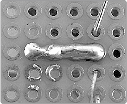
FIGURE 12-11: The pretty method for connecting components on generic PCBs
Bridging Connections the Easy Way
First, bend the stray end of one lead so that it runs straight along the row of holes, touching the other leads (see the left image in Figure 12-12, where I bent the input capacitor lead over to touch the resistors and transistor base). Next, heat the length of that bent lead with your soldering iron until the three other solder points remelt. Add more solder to each joint if you need to so that they make a solid connection with the bent lead. Finish by trimming the ends of the four leads once the solder has cooled. The final result is shown in the right image in Figure 12-12. The result isn’t as slick, but it’s just as serviceable.
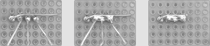
FIGURE 12-12: The easy method of connecting components on generic PCBs
Step 15 Now install the 10 μF output capacitor, keeping in mind that the stripe on the cap’s body indicates the negative leg. Mount this cap with the positive leg in the first open hole above the transistor and insert the negative leg three columns to the right, as shown in Figure 12-13. Solder the positive leg to its pad.
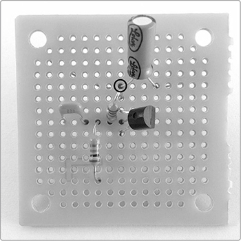
FIGURE 12-13: The 10 μF capacitor in place
Step 16 Insert one leg of the 10k ohm resistor (brown-black-orange stripes) into the first open hole above the positive leg of the output cap that you just installed. Insert the other leg four holes to the left in the same row, as shown in Figure 12-14.

FIGURE 12-14: Connecting the 10k ohm power supply resistor
Step 17 Solder the rightmost leg of the 10k ohm resistor to its pad. Then use one of the solder-bridging methods from Step 14 to connect that leg to the three directly below it: the positive leg of the output capacitor, the 1M ohm resistor, and the transistor’s upper leg. You should have the four circled leads in Figure 12-14 connected. Clip the excess leads after the solder joint has cooled.
Step 18 Finally, mount the 10 ohm resistor (brown-black-black stripes). Bend the resistor into a U and run one lead into the first open hole to the right of the transistor’s lower leg (also called the emitter). Insert the other lead into the fourth hole down in that same column (see Figure 12-15). Solder the resistor lead to its pad, solder the transistor’s lower leg to its pad, solder the two leads together, and clip the excess wire.
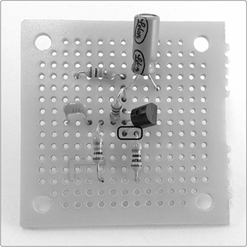
FIGURE 12-15: Mounting and connecting the 10 ohm ground resistor
With all of the board components mounted, it’s time to add the hardware you built in “Prepare the Hardware” on page 202.
Step 19 Start with the output jack, which is the jack without a potentiometer attached. It has one insulated lead. Insert this into the first open hole to the right of the negative leg of the 10 μF output capacitor (see Figure 12-16). Solder the output lead to its pad and the negative capacitor leg to its pad, and then solder the two to each other. Clip the excess wires.
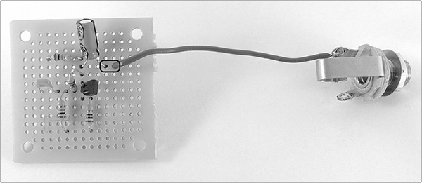
FIGURE 12-16: Adding the output jack
Step 20 Next, add the volume control/input jack and the tone control knob. Take the volume control pot and insert the insulated lead into the hole immediately above the 0.1 μF input capacitor. Now add the insulated lead from the tone control to the first hole below this capacitor (these wires are highlighted in Figure 12-17). Solder each lead and the capacitor leg to its respective pad, and then solder both leads and the capacitor together. Trim away excess wires once the solder joint cools.
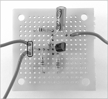
FIGURE 12-17: Completing the input. The upper lead connects to the volume control, and the lower one connects to the tone control.
Step 21 Time to add power! Take the power switch assembly from Step 6 and insert the insulated wire into the first open hole to the left of the 10k ohm resistor (brown-black-orange stripes), as shown in Figure 12-18. Solder the power wire to its copper pad, solder the free 10k ohm resistor leg to its copper pad, and then connect the two. Trim the leads.
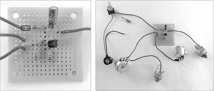
FIGURE 12-18: Power is installed, but the ground is still incomplete (detail at left, full circuit at right)
The circuit is nearly finished; it’s just missing the ground connection (for reference, the completed, groundless circuit is shown in the right panel of Figure 12-18). Right now you have two components connected (but not yet soldered) to the row of holes that will serve as the common ground linking your circuit to the battery’s negative terminal: a 1M ohm resistor (brown-black-green stripes) and a 10 ohm resistor (brown-black-black stripes).
In order for the circuit to actually function, we’ll need to run the ground connection to all of the hardware. There are a variety of ways to accomplish this. In this case, we’re using a star ground, where each component gets its own direct connection to the ground (this minimizes unwanted noise and interference from local AM stations, wireless devices, high-voltage appliances, and so on). You’ll now add the final six connections to the ground: the input and output jacks, both controls, the indicator LED, and the negative power supply lead.
Step 22 Start with the black wire from your battery clip—that is, the ground wire itself. Place it in the hole in the ground row between the two resistors, as shown in Figure 12-19. Solder it to its pad.
Step 23 Cut a length of 22-gauge bus wire long enough to reach from the PCB to the input jack. Solder it to the open lug on your input jack and then run it into one of the open holes in the common ground row. Solder it to its pad.
Step 24 Cut another length of 22-gauge bus wire, long enough to reach from the PCB to the output jack. Solder it to the open lug on your output jack and run it into one of the open holes in the common ground row. Solder it to its pad.
Step 25 Cut two more wires long enough to comfortably run from the PCB to the controls, which are likely to go on the enclosure’s lid. Solder one wire to lug three on the volume pot; solder the other wire to the open leg of the capacitor on the tone control. Insert both into holes on the ground row and then solder them to their pads.
Step 26 Cut a final length of wire long enough to run from the negative leg of the indicator LED to the ground bus. Solder one end to the LED’s open leg and the other to the ground row. Solder it to its pad. Now that you have all eight connections in place, solder them all together using one of the two methods described in Step 14 and trim any excess wire. When viewed from the top (that is, the side with no copper solder pads), your ground row should look like Figure 12-19.
Now that the circuit is built, let’s mount the hardware on the case.
Step 27 Add holes to your enclosure to accommodate the switches, jacks, and controls. You’ll need drill bits that correspond to the size of these components; in general, the following works: 3/16 inch for the LED, 1/4 inch for a small switch, 3/8 inch for a jack, and either 5/16 or 3/8 inch for a potentiometer (although your components may be slightly different dimensions; double-check before you drill). Decide where you want your components to go and drill the appropriate holes. I like to have indicator LEDs and controls, including power, on the face of the enclosure and jacks on the sides (see Figures 12-1 and 12-21).
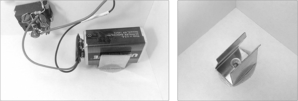
Step 28 Once you’ve drilled the enclosure, secure your battery. If the enclosure is too large, the battery is likely to rattle around, causing short circuits or damage to sensitive components. To prevent the battery from busting up the place, I suggest screwing a 9-volt battery holder into the side of the enclosure, as shown in Figure 12-20. (If you have a fairly snug-fitting enclosure, you can often omit the battery holder.)
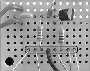
FIGURE 12-19: The completed common ground row. Note that the wires are all bunched together with no open holes and the negative battery lead—which is the ground—is at the center.
FIGURE 12-20: A 9-volt battery holder clip in a finished project, with and without a battery in place
Step 29 Mount the switch, jacks, and potentiometers on your enclosure. These come with their own mounting hardware. If that includes two washers, then put one inside the enclosure and one outside. If there’s only one, put it on the outside of the enclosure. You should be able to press the LED into place and have it stay put on its own. Finally, add the control knobs to the shafts of your pots.
At this point, all of your basic hardware should be mounted, and the PCB should be floating freely, as shown in Figure 12-21—but before you close that lid, make sure your circuit works!
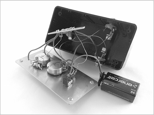
FIGURE 12-21: The finished Mud-n-Sizzle Preamp with its guts showing
The enclosure is simply the box for your electronics project: drill a few holes, stuff in the batteries and wires, label your knobs and jacks, and you’re good to go. You can get cheap, sturdy electronic project enclosures, like the one I’ve used for this preamp, at any hobby shop that specializes in electronics or online (try searching for project box or project enclosure). For something fancier, you can get the professional-grade die-cast enclosures made by Hammond Manufacturing and Velleman Incorporated. Small Bear Electronics (http://www.smallbearelec.com/) and Antique Electronic Supply (https://www.tubesandmore.com/) sell a variety of traditional stompbox-style enclosures. If you’re looking for something simpler, plastic or wooden storage boxes from any office or craft supply store are perfectly suitable. Even plastic food-storage boxes sold at the grocery store will do in a pinch. On the other hand, you can also go quaint: keep your eyes peeled for old cigar boxes, pencil boxes, candy or cookie tins, lunch boxes, or military surplus equipment cases and kits.
Questions to consider when choosing enclosures:
 Is it conductive or nonconductive? A conductive metal enclosure is great for a project like a preamp—which often benefits from the extra shielding—but it can cause short circuits if the PCB brushes up against unpainted metal.
Do you have access to the tools needed to modify the enclosure? You’ll need to add holes for jacks, switches, and pots; you can cut through an old plastic pencil box with a pocketknife, but you’re going to have trouble piercing a steel ammo case with anything short of a drill press.
Is the box big enough? It needs to accommodate the battery and the jacks with plugs inserted as well as the circuit itself. Cramming too much into too small a case is a recipe for annoyingly intermittent short circuits.
Will the box be able to withstand the abuse? A pretty little Chinese gift box might make an awesome Droid Voicebox (Project 6) or handheld synth but probably isn’t sturdy enough for a preamp, Twin-T Phaser/Wah (Project 14), or amplifier, all of which will tend to get knocked around a bit.
And finally: does it look frikkin’ awesome?
Time to power up and test out the circuit! Before connecting the battery, do a quick visual check to make sure all of your soldered connections are indeed connected, with no wire left unsoldered. Figures 12-18 (which shows everything but the ground connections) and 12-19 (which gives a tight detail of the star ground) are good references for this check, as is the schematic in Figure 12-3.
Step 30 When you’re satisfied that everything is wired properly, connect a battery, flip the power switch, and check to see that the LED lights up. If the LED doesn’t light, make sure that your battery isn’t flat and that the ground connection is complete. Then, check for short circuits. Are bare wires brushing up against the PCB? Move them so that they aren’t making contact. Are there stray snips of wire or solder resting on the PCB, or stuck to a switch or pot? Remove them. Are there gobs of solder connecting adjacent components that shouldn’t be connected? Remove them (see “Desoldering” on page 349 for details).
Step 31 Once your preamp has working power, turn it off, turn the volume knob all the way down (fully counterclockwise), and set the tone knob to the center of its range. Connect an amplifier to the preamp’s output jack, power up the amplifier, and then power up your preamp. There should be no sound beyond a quiet hum. If you bring up the volume on the preamp, you should get a louder hum. If you’re getting excess noise or AM radio, check the ground connection and the length of the leads. Any lead longer than 8 inches should be shortened. If all else fails, consider moving your innards to a partial or all-metal enclosure, which will shield the circuit from electromagnetic interference, an effect you can maximize by running a piece of bus wire from the star ground to a metallic portion of the enclosure. (This is traditionally accomplished by soldering one end of the wire to the ground and then wrapping the other end around one of the lid’s mounting screws so the wire gets sandwiched between the case and lid when you screw it shut).
Step 32 Once the unwanted noise is eliminated, power the preamp down and connect a low-level instrument to the input jack, such as the Robo-Tiki Steel-Stringed Ukulele (Project 10), Twang & Roar Kalimba (Project 11), or a standard electric guitar without active electronics (guitars and basses with active electronics have a builtin preamp wired directly into the pickups; as a rule, if an instrument has a battery, then it has active electronics). Once the instrument is hooked up, switch the preamp back on and slowly bring up the volume while you strum, pluck, flick, tweak, or otherwise play the instrument. You should get a pretty loud signal quickly, one that’s obviously louder than if you plugged the instrument directly into the amp.1 With the volume at the extreme clockwise position, you may even get a fuzzy kind of distortion known as clipping.
Step 33 Now turn the volume back to the point where the signal is both loud and clear, and then begin turning the tone control knob counterclockwise. You should hear the signal make a very definite shift toward bass-heavy rumble. The filter controlled by this knob is a low-pass filter, meaning that as it engages, it eliminates an increasing portion of the higher frequencies in the signal while permitting the lower frequencies through to the output—that is, it lets the low frequencies pass and shunts the highs to ground. Try playing a variety of notes to get the clearest sense of what’s going on. Now turn the tone knob clockwise. The tone should clear as the filter disengages. Keep turning clockwise and the tone will shift into a buzzy sizzle, emphasizing the higher-frequency components of each note. If you aren’t getting an obvious effect, check your PCB for short circuits, which are often either between the tone potentiometer’s input and ground connections or between some point on the PCB and ground.
Step 34 When you’re confident your circuit works, install the PCB into the enclosure. Prefab PCBs often come predrilled with larger holes (usually in the corners or centered along two edges) for bolting the PCB to the inside of the enclosure. Many purpose-built enclosures are designed with slots, stand-offs, or bolt-holes for just this purpose. Just slot the PCB into place or bolt it down. For other enclosure types, you can either drill the case and bolt the PCB in place or secure it with a couple pieces of foam-backed double-sided tape.
A preamp is pretty straightforward: just plug in your instrument and find the volume and tone you want, and then you’re ready to rock. There are lots of possibilities to explore when you make little sounds big—for an example, check out the work of Ryoji Ikeda. You might have fun connecting this preamp directly to a stand-alone Plasti-Pickup (Project 2) or Playing-Card Pickup (Project 9) and exploring your local soundscape.
But primarily, preamps are seen as utilitarian workhorses. In addition to beefing up your sound and giving your amp and effects more to work with, a small battery-powered preamp like this can help you eliminate unwanted noise. Place the preamp early in your effects pedal chain, as close as possible to your instrument and on the shortest possible cable. This way, your boosted signal is as pure as possible, assuring that more signal—and thus less noise—reaches the effects, mixing board, recorder, or power amp driving the speakers in your instrument amplifier.
You can customize your Mud-n-Sizzle Preamp in all sorts of ways, from swapping in new components to building the preamp into an existing instrument.
If you like the fuzzy overdrive sound you get when the volume is cranked all the way up, want an even more aggressive fuzz, or just need to boost a very weak signal even further, you can supercharge this preamp by replacing the single transistor with a Darlington pair. This is a set of matched transistors wired so that the first transistor amplifies the signal and the second transistor amplifies that amplified signal.
You can buy single-package Darlington pairs that look just like plain old transistors and will directly replace the 2N3904 shown in the circuit diagram in Figure 12-3. The 2N6426, 2N6427, and MP3A13 are all workable substitutes, with the first having the highest gain by a wide margin. Or, you can build a Darlington pair yourself by taking two 2N3904s and soldering them together, as shown in Figure 12-22.
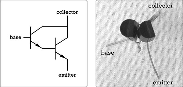
FIGURE 12-22: A homemade Darlington pair (schematic at left, in real life at right)
This homebrew Darlington can replace the single 2N3904 in your circuit. Just treat its conjoined collector as though it was the collector of a single transistor. The base of the “rear” transistor in the Darlington pair then replaces the single transistor’s base, while the Darlington’s “front” transistor’s emitter replaces the single transistor’s emitter.
* NOTE: If you really like the fuzztone sound, you might consider building the “Two-Transistor Fuzztone” on page 364, which uses a Darlington pair and adds a few diodes to get a rich British Invasion–style fuzz with increased sensitivity and sustain.
To get a bit more fuzztonally experimental, consider changing the values of the two 1M ohm resistors. In the circuit we’ve just built, they form a voltage divider that biases the transistor’s base—that is, keeps the transistor ready to hear an incoming signal at a moment’s notice. My goal was to make a preamp that could reliably and faithfully amplify even very low-level signals, and I selected these resistors accordingly. But there’s no reason that these two resistors have to be 1M ohm or even the same value. Try experimenting with values in the 100k ohm range or lower, eliminating the base-to-ground resistor entirely or replacing the 1M ohm resistor running between the collector and base with a potentiometer. Using a potentiometer allows you to adjust the circuit’s bias on the fly, changing the amp’s sensitivity, timbre, or perceived gain. Just remove the 1M ohm resistor and connect the pot’s middle lug to the transistor’s base and either of the outer lugs to the collector. A 1M ohm potentiometer with a linear taper is a reasonable place to start, but feel free to experiment—maybe even get weird by using a photoresistor, body contacts, or other nonstandard resistor scheme here. (The Universal LFO from Project 13? Why not?!)
Some instruments come with built-in preamps. This is especially the case with nicer bass guitars, heavy metal axes, and any instrument that usually produces a line-level output, such as a synthesizer, drum machine, or keyboard. If you’re told that a guitar has “active electronics” or “active pickups,” then it has a built-in preamp wired directly to the pickups.
You could build your Mud-n-Sizzle Preamp into an instrument, too. Be the envy of your block with a homemade cigar-box uke with active electronics! Here are a few tips:
Leave off the instrument’s output jack and the preamp’s input jack (the preamp’s output will now serve as the instrument’s output, too). Run your pickup’s leads directly to the preamp circuit (one pickup lead will go to the input and the other to the common ground; it doesn’t matter which wire goes where).
Any unshielded wire2 that carries an audio signal should be less than 8 inches long. Play it safe and keep all your wires under 6 inches when possible. This prevents interference from seeping into the circuit. Transistor-based amps are notorious for picking up local AM stations, baby monitors, and so on.
If space is at a premium, you can leave out the mud-n-sizzle tone and volume controls. These can be eliminated without further modifications to the circuit. You can also eliminate the toggle power switch by replacing the output mono jack with a stereo jack wired for “jack power” (see “Stereo Jack-Power Switch” on page 358 for details). With a stereo jack power switch, the preamp automatically powers up when you plug in your instrument—no additional hardware required. Very slick.