Even if you have no idea what a wah-wah pedal is, you know the sound. Wah-wahs are responsible for the crying, voice-like articulation in countless rock classics—Jimi Hendrix’s “Voodoo Child” is a great example—as well as the funky-see funky-do wakka-chikka-wakka rhythm guitar in tunes like Isaac Hayes’s Shaft theme. The technical name for this effect is spectral glide, which means the “modification of the vowel quality of a tone.” In this case, the modification emphasizes the waaahs, wooowwwws, and aooows. Control the spectral glide with a foot pedal, and you have a wah-wah pedal. Automate it with an LFO (like the Universal LFO in Project 13), and you have a phaser effect. Tweak it with a plain old knob, and you can do manual filter sweeps, just like your favorite analog synth aficionado or eurotrash club DJ. The Twin-T Phaser/Wah in this project packs all of this into one cigar box.
Traditional wah-wah pedals are tricky to build at home: they need to endure a lot of mechanical abuse, so they require a purpose-built, heavy-duty potentiometer and a specialized rocker-pedal enclosure. Our Twin-T Phaser/Wah dispenses with the mechanical pedal control and instead uses a faux pedal made from a light-sensitive photoresistor. By covering and uncovering the photoresistor with your foot, you control the amount of light hitting it, allowing you to sweep the filter back and forth across its full range, articulating the waaahs and aooows while your hands are otherwise occupied.
There are a lot of features here, giving you plenty of options—and plenty of chances to make a wrong turn. Read this project fully in advance—especially “Using the Twin-T Phaser/Wah” on page 261 and “Tips, Tricks, and Mods” on page 262—so you can make some decisions before you get to snipping and soldering.
Hear the Twin-T Phaser/Wah in action in the samples at http://www.nostarch.com/jamband/.
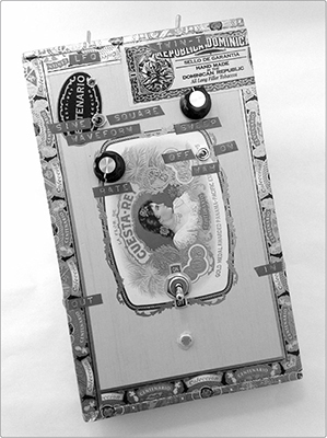
FIGURE 14-1: The finished Twin-T Phaser/Wah
Build Time
 About an hour
Tools
A standard soldering kit (See page 340.)
A ruler that shows 1/4-inch increments or smaller
An electric drill with bits (You’ll probably need 3/16-inch, 1/4-inch, 5/16-inch, and 3/8-inch bits.)
(Optional) Other tools to work your enclosure (If you’re using a wooden enclosure, you’ll want sandpaper and possibly files to clean up drill holes.)
(Optional) Foam-backed double-sided tape or hardware to mount the circuit in its enclosure
(Optional) A hacksaw for trimming down potentiometers with long shafts
Supplies
A 2N3904 NPN transistor, such as Mouser part #512-2N3904BU
A red LED
Three 0.1 μF capacitors (marked 104)
Two 0.0047 μF capacitors (marked 472)
A 0.01 μF capacitor (marked 103)
Two 1M ohm resistors (brown-black-green stripes)
A 470 ohm resistor (yellow-violet-brown stripes)
Two 470k ohm resistors (yellow-violet-yellow stripes)
A 33k ohm resistor (orange-orange-orange stripes)
A 10 ohm resistor (brown-black-black stripes)
A 10k ohm resistor (brown-black-orange stripes)
A 50k ohm variable resistor (Variable resistors are also called potentiometers or pots; see “The Gory Details: Audio Taper vs. Linear Taper” on page 327.)
A control knob that fits your variable resistor
A photoresistor (This may also be called a light-dependent resistor, a cadmium sulfide (CdS) cell, or a photocell. Digi-Key part #PDV-P8105-ND is an example.)
Two small SPST toggle switches (You can use Mouser part #108-MS550K, for example, but any similar switch will work.)
A DPDT switch (Mouser part #612-100-DP1T8 or Digi-Key part #EG2410-ND will work, and your local hardware store likely offers plenty of other viable options.)
A 9-volt battery clip
An Adafruit Perma-Proto Quarter-sized Breadboard PCB (Adafruit product #589 or Maker Shed product #MKAD48)
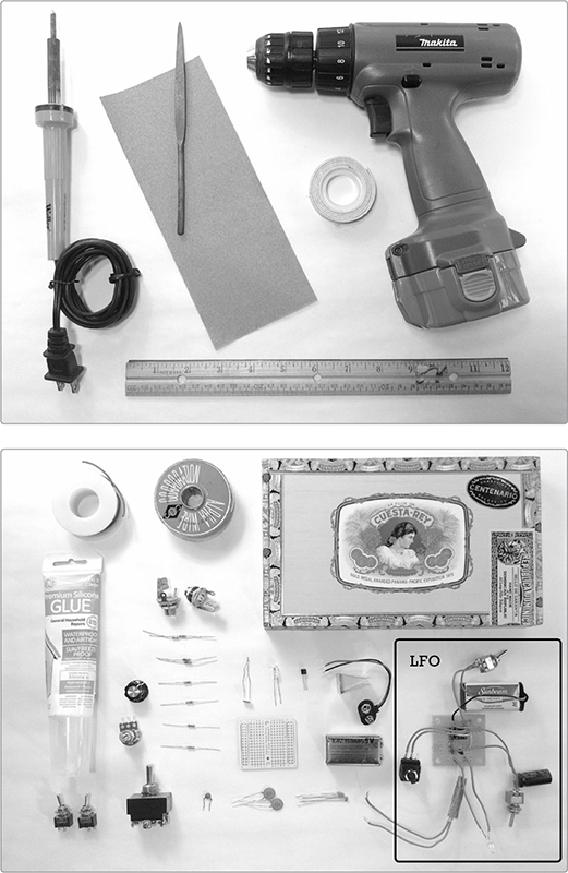
FIGURE 14-2: Tools and supplies (not shown: hacksaw). The completed Universal LFO (Project 13) is shown in the lower-right corner.
24-gauge insulated hook-up wire (Stranded wire is fine, but it’s best to have both stranded and solid core in several colors.1 Unless otherwise specified in the build instructions, you can always assume that stranded wire is fine.)
22- or 24-gauge bare bus wire (This is uninsulated solid core wire. Because you need only a short length of bus wire for this project, you can get away with using a scrap of wire, a leftover bit snipped from a component lead, or even a piece of a paper clip.)
Two 1/4-inch mono phone jacks, also called guitar jacks
Silicone-based household glue, sometimes called room-temperature vulcanizing rubber or RTV-1
A sturdy enclosure (If you’re going the LFO route, make sure there’s room enough for two circuit boards and batteries. See “On Enclosures” on page 214 for more information.)
(Optional) A 9-volt battery holder clip, such as Digi-Key part #71K-ND or Mouser part #534-071
(Optional) A Universal LFO (While this is optional, it’s super awesome and vital if you want the twin-T to have full phaser functionality. See Project 13 for instructions.)
As with other projects, we’ll begin by soldering the hardware. (Need a soldering refresher? Check out “Soldering” on page 346.)
In this section, we’ll build the sweep control, the power switch, and the bypass switch.
* NOTE: If you’re omitting the LFO phaser control or photoresistor wah pedal, you can skip some of the wiring in this first step (and then skip installing those pieces down the road in “Add the Phaser/Wah” on page 257). Read all of Step 1 before snipping, stripping, or soldering anything.
Step 1 First, we’ll build the sweep control. Take the 50k ohm potentiometer, or pot, and one of the SPST switches. Cut four 4-inch lengths of wire and two 6-inch lengths, and strip and tin the ends of each.
One pair of 4-inch wires will connect the sweep-control pot to the twin-T circuit—that pair is mandatory. The other two 4-inch wires will ultimately connect to the LFO. Both 6-inch wires and the SPST switch are for the photoresistor wah pedal. So if you’re going to skip the LFO, the pedal, or both, omit their leads now.
For a fully loaded project (one that includes both the LFO and photoresistor wah pedal), take two of the 4-inch wires and one of the 6-inch wires and twist their ends together. Solder these three twisted wires to lug 2 of the pot. (Pot lugs are numbered from left to right when the shaft is facing you, as shown in Figure 14-3.) Repeat this with another set of two 4-inch wires and one 6-inch wire, soldering them to lug 3. If you’re going to skip the wah pedal, then just solder two 4-inch wires to lug 2 and two to lug 3. If you want to skip the LFO and keep the wah, then you’ll solder one 4-inch and one 6-inch wire to each of these lugs. And, if you’re skipping all the extras, then you’ll just have a single pair of 4-inch leads, one connected to lug 2, the other to lug 3.
If you’ve included the 6-inch wires for a photoresistor wah pedal control, then solder the free end of lug 3’s 6-inch wire to either of the terminals on the SPST switch. The resulting fully loaded sweep-control pot is shown in Figure 14-3.
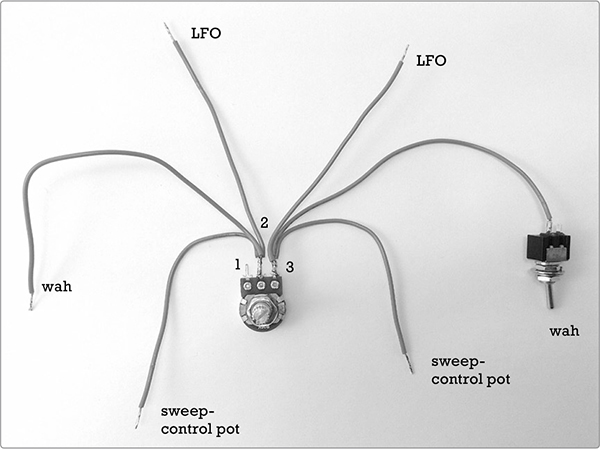
FIGURE 14-3: The fully loaded sweep control. If you are omitting the photoresistor wah, then this pot will just have the four 4-inch leads—no 6-inch wires and no switch. If you’re omitting the LFO and the wah, then the pot will have just two 4-inch wires, one soldered to lug 2, the other to lug 3.
Step 2 Next, we’ll build the power switch with indicator LED. Take out the 9-volt battery clip, the other SPST switch, the 470 ohm resistor (yellow-violet-brown stripes), and the LED. Cut, strip, and tin a 4-inch length of insulated wire. Solder the positive (red) battery clip lead to either lug on the switch. Solder one leg of the 470 ohm resistor to the positive leg of the LED. (The positive leg is longer; the negative leg aligns with the flat spot on the side of the LED lens.) Finally, twist the remaining leg of the resistor to one end of the 4-inch lead and then solder this twisted pair to the empty switch lug. Check out the results in Figure 14-4.
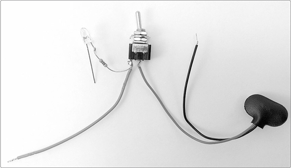
FIGURE 14-4: The finished power switch with indicator LED
Step 3 The last piece of hardware is the bypass switch, which will allow you to bring the Twin-T Phaser/Wah in and out of your effects chain without unplugging a bunch of stuff. We’re using a standard DPDT toggle switch. Cut a short length of bare bus wire and run it diagonally from lug 1 to lug 6. Solder this in place (or screw it down if you have screw terminals like the ones shown in Figure 14-5). Then cut, strip, and tin two lengths of insulated wire. Solder one insulated lead to lug 2 and the other lead to lug 4.
* NOTE: The left image of Figure 14-5 shows a standard DPDT toggle switch (on the left) and a heavy-duty DPDT stomp switch (on the right). The standard switch is easy to find—any hardware store will have it. The stomp switches—which are the sort used in old-school commercial guitar effects (often called “stomp boxes”)—will need to be special ordered (see “Guidelines for Sourcing Components” on page 323). Both wire in the same way, as shown in the right panel of Figure 14-5.
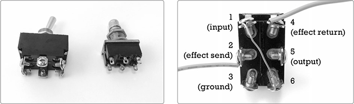
FIGURE 14-5: Two styles of DPDT switch with two different styles of lugs (left)—both wire up the same way (right)
Step 4 Take out your two jacks and prepare two more lengths of 4-inch wire. Solder one 4-inch wire to the tip lug of each jack; if you’re unsure where the tip is, check out “Quarter-Inch Phone Plugs and Jacks” on page 337. Figure 14-6 shows the finished jacks.
Step 5 Now add the input and output jacks to the bypass switch. The jacks are identical at this point, so it doesn’t matter which goes where. Connect the lead from one jack to lug 1 of the DPDT switch and the lead from the other jack to lug 5 (see Figure 14-7). Set aside all the hardware—sweep-control pot, power switch, and bypass switch—for later.
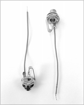
FIGURE 14-6: Input and output jacks
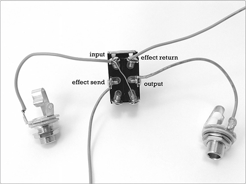
FIGURE 14-7: The finished input/output/bypass
It’s time to look at the schematic, shown in Figure 14-8. As with the Universal LFO, this is probably best understood as two circuits linked together: the top half—centered on the transistor—is an amplifier, while the bottom half—mostly composed of resistors and capacitors—is a filter.
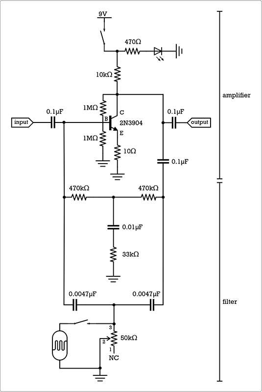
FIGURE 14-8: The circuit diagram for the Twin-T Phaser/Wah
The amplifier section probably looks familiar; it’s basically the same preamp circuit that we used for the Mud-n-Sizzle Preamp (Project 12). The bottom half is a little more complicated. Wah effects are usually created using an adjustable band-pass filter, which is a filter that emphasizes a narrow band of frequencies. The popular Cry Baby wah-wah pedals rely on an inductor-based band-pass filter, and that design is widely imitated. But sourcing a suitable inductor for such a band-pass filter can be kind of tricky. Instead, we’ll build a resistor/capacitor-based twin-T band-stop, or notch, filter. A notch filter attenuates—or even cuts—a narrow band of frequencies, allowing the rest to be more prominent. This is technically the opposite of how most wahs work, but the result sounds very similar.
Take a quick look at the filter portion of the circuit in Figure 14-8. You’ll immediately see how the twin-T got its name: the heart of the filter is a set of three resistors and three capacitors, arranged into a pair of Ts. Each T bridges the input and output with its bar and connects to the ground with its stem.
First, let’s build the preamp. Since the Adafruit PCB has its columns numbered and rows lettered, I’ll use those coordinates here. If you’re using a different brand of PCB, make sure to check your work against the figures
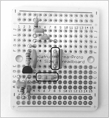
Step 6 We’ll start by placing the four jumpers shown in Figure 14-9. Cut, strip, and tin two 3/4-inch lengths of insulated wire. Bend them into little flat-bottomed Us. Run the first jumper from 4E to 4F, bridging the central divide at the 4th column. Run the second jumper from 9E to 9F, bridging the divide at the 9th column. Flip the board and solder each end of each jumper to its respective trace.
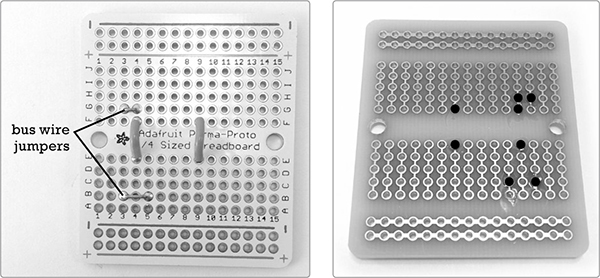
FIGURE 14-9: The four jumpers soldered in place. Notice the bare bus wire jumpers, which are a little harder to see. The right image shows the underside of the PCB at this step. (Black dots indicate the solder points completed in Steps 6 and 7.)
Step 7 Now snip two 3/4-inch scraps of bare bus wire. Bend one into a flat-bottomed U, and run it from 3B to 5B, connecting columns 3 and 5 along the row second from the bottom. Take the other snip of bus wire, fold it in half, and run it from 3G to 4G, linking columns 3 and 4 above the central divide. Flip the board and solder these. Check the results against Figure 14-9.
Step 8 Next is the transistor. These NPN transistors have a black body, flat face, and three legs. If the face is toward you and the legs down, then those legs are, from left to right, the emitter, base, and collector. Mount the transistor so that its emitter is in 2D, its base in 3D, and its collector in 4D, as shown in Figure 14-10. Solder these legs now.
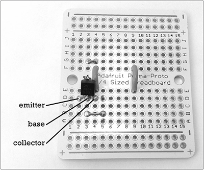
FIGURE 14-10: The transistor is in place.
Step 9 Now connect the 1M ohm bias and ground resistors (brown-black-green), both of which connect to the transistor’s base leg. The bias resistor runs from 3E to 3F, bridging the divide. The ground resistor runs from 3A to the third pad in the row directly below the blue line (labeled with a – sign), which serves as the common ground rail. Figure 14-11 shows both resistors.
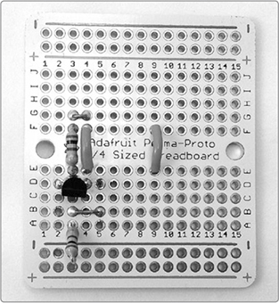
FIGURE 14-11: The 1M ohm bias and ground resistors are installed.
Step 10 Add the last two resistors to the preamp portion of the circuit. These are the ground and power resistors. Run the 10 ohm ground resistor (brown-black-black) from 2B to the second hole from the left in the common ground row directly below the bottom blue line. The 10k ohm (brown-black-orange) resistor runs from 4J to the row just above the red + line at the top—that is, the power rail (see Figure 14-12). Solder these now.
Step 11 Finish off the preamp with the 0.1 μF input and output capacitors. These little caps are marked 104 (although those markings can be downright infinitesimal; keep a magnifier handy). The input cap runs from 1C to 3C. The output cap runs from 4I to 6I. Solder these now and compare them to Figure 14-13.

FIGURE 14-12: The preamp ground and power resistors are installed.
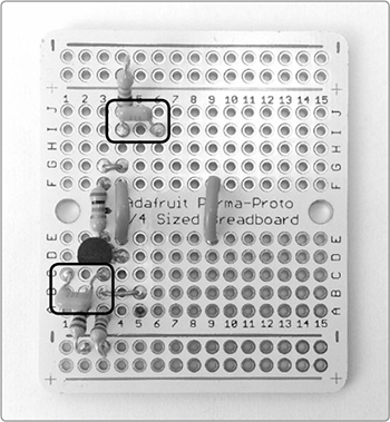
FIGURE 14-13: Installing the input and output capacitors
The twin-T circuit consists of a resistor T and a capacitor T. (In Figure 14-8, the resistor T is the upper one, and the capacitor T the lower.) The resistor T is made from two 470k ohm resistors (yellow-violet-yellow stripes), a 33k ohm resistor (orange-orange-orange stripes), and a 0.01 μF capacitor (labeled 103). The capacitor and orange-striped resistor form the stem of the resistor T, and the two 470k ohm resistors form its top bar. The capacitor T consists of the two 0.0047 μF capacitors, with the 50k ohm pot and photoresistor forming its stem.
Step 12 Run the remaining 0.1 μF capacitor from 4H to 8H, as shown in Figure 14-14. Then solder it. This cap will serve as the link between the preamp output and the twin-T filter output. The filter input connects directly to the preamp input.
Step 13 Run one 470k ohm resistor (yellow-violet-yellow stripes) horizontally from 5C to 8C and the other vertically from 8E to 8F, bridging the divide, as shown in Figure 14-15.
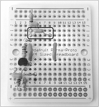
FIGURE 14-14: Placing the final 0.1 μF cap, which links the filter and output
FIGURE 14-15: The two 470k ohm resistors in place
Step 14 Add the 0.01 μF capacitor horizontally from 8D to 10D (see Figure 14-16). The final 33k ohm resistor (orange-orange-orange stripes) will vertically connect that 0.01 μF capacitor to the ground, running from pad 10A straight down to the ground rail, as shown in Figure 14-17. (You’ll note that none of this looks even remotely like a T once it’s laid out on the PCB.) Solder all these fellas down now.
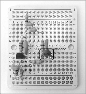
FIGURE 14-16: Adding the 0.01 μF capacitor to the resistor T
FIGURE 14-17: Finishing off the resistor T with a 33k ohm resistor linking the 0.01 μF capacitor to the ground
Step 15 To start the capacitor T, go find the two 0.0047 μF caps labeled 472. Place one horizontally from 5A to 9A and the other horizontally from 8G to 9G, as shown in Figure 14-18. Solder them in place.
Step 16 Take the sweep-control pot from Step 1. Solder one of lug 3’s two remaining 4-inch leads to 9B on the circuit board. Next, solder one of lug 2’s 4-inch leads to the common ground at column 4 (see Figure 14-19). Reminder: if you left out the wah or LFO leads in Step 1, you’ll have fewer leads here now. That’s just fine. Do not panic. What’s important is that lug 3 is connected to pad 9B, and lug 2 is connected to the ground.
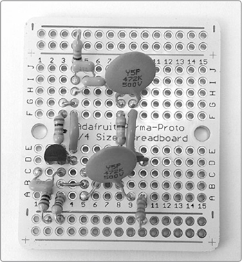
FIGURE 14-18: Starting the capacitor T in the twin-T filter
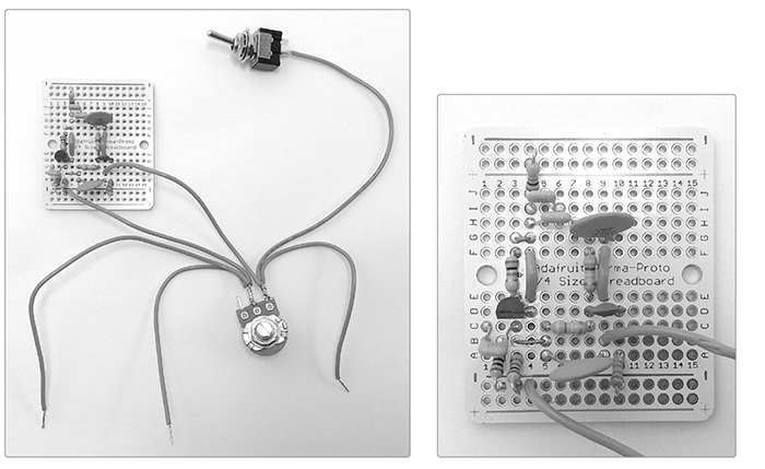
FIGURE 14-19: The sweep control is installed (detail on the right shows more clearly where the control hooks into the circuit).
Now that the circuit itself is complete, we’ll connect the input and output jacks and the power switch. Then, we’ll be ready to test the twin-T filter.
Step 17 Solder the lead connected to lug 2 of the DPDT bypass switch to pad 1E on the PCB (that’s the lead going from the switch to the left edge of the PCB in Figure 14-20). This is the circuit input. Solder the lead connected to lug 4 of the DPDT switch to 6J, which is near the top of the PCB. This is the circuit output.
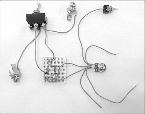
FIGURE 14-20: The installed input, output, and bypass switch
Step 18 Let’s add power! Get out your power switch/LED assembly and connect the black wire from the battery clip to the leftmost hole on the ground. Connect the loose red wire from the switch to the power rail, just above the red line (labeled +), in the leftmost hole. Solder all of these, and your PCB should look like Figure 14-21.
Step 19 Connect the grounds. For the following connections, you can use any open hole in the common ground rail, which is just below the blue line (labeled –) at the bottom of the PCB. Start by connecting the open negative lead on the LED to any open hole on the ground rail. Then, wire each jack’s open lug to any open ground hole. Finally, run a length of wire from lug 3 of the DPDT switch to the ground. Solder all of these.
* NOTE: Although many folks use bare bus wire for ground connections like these, I recommend insulated wire in this case. There are so many wires floating around, it would be easy to create a short circuit with bare ground connections here. For clarity in the images, I’ve used black insulated wire.
FIGURE 14-21: Our circuit has power!
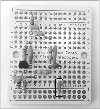
In Figure 14-22, all of the ground connections from Step 19 are in black, as is the negative battery lead you soldered in Step 18. On the right is a close-up of the finished PCB with all of the connections labeled. Note that all the ground connections go to the common ground along the bottom of the PCB, just below the blue line marked with a minus sign.
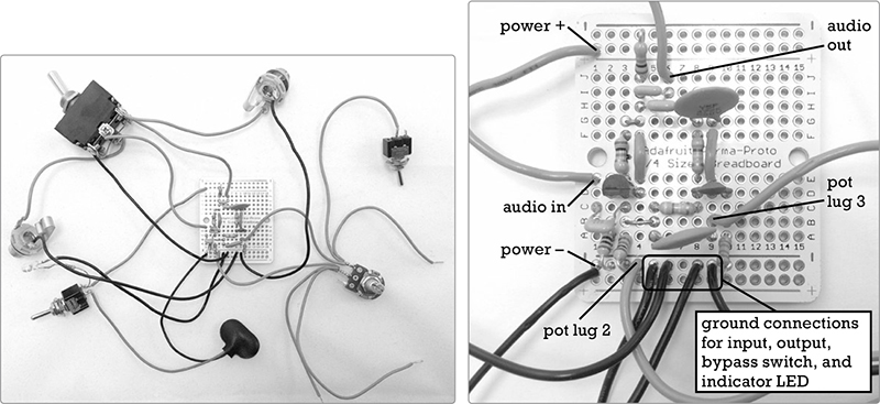
FIGURE 14-22: The core twin-T circuit with the ground fully wired
Before installing the photoresistor wah control and LFO, we’re going to do some quick testing.
Step 20 Snap a 9-volt battery into the battery clip and flick the DPDT bypass switch up to the lug 1/lug 4 side. If the indicator LED isn’t already illuminated, flip the power switch. If the LED still doesn’t power up, check for short circuits and solder bridges—both between tracks and solder pads on the PCB and between the lugs of switches, pots, LED leads, flying wires that run to the various pieces of hardware, and so on. I describe remedies in “General Troubleshooting” on page 355, but as a rule, if two things are touching that shouldn’t touch, separate them. Also make sure your battery isn’t dead.
Once you have power, plug the output into an amplifier, turn the amp on, and crank the amp to its highest setting. You should hear a hum, and when you run the Twin-T’s sweep control pot clockwise and counterclockwise, you’ll give that hum a sweeping whoosh. If you don’t get any whoosh, flip the DPDT switch again.
Still nothing? Search for more short circuits and solder bridges, especially in the twin-T filter section. If you’re hearing AM radio, try connecting the common ground to a piece of metal. You can do so using an alligator clip for now: just attach one end of the clip to one of the grounded legs of one of the resistors or to the ground lug on one of the jacks, and attach the other end to a steel saucepan, metal desk, aluminum pie pan, or something similar.
When you have the twin-T circuit working, plug in an unpowered instrument, such as a standard electric guitar or a Robo-Tiki Steel-Stringed Ukulele (Project 10) sporting the hotter 42-gauge wire pickup. Turn the volume on your amp down to a comfortable level. (Remember that the built-in preamp will give the signal a pretty hearty boost.)
Pluck a string, run the pot, and soak up the funk. You should hear a distinct spectral sweep as you twist the knob. Once you’ve noodled around a little, power everything down and remove the battery. If you’re skipping the photoresistor wah pedal and LFO control, then you’re done, and you can jump to “Final Testing and Enclosure” on page 259. Otherwise, keep going with “Add the Phaser/Wah” next.
The Universal LFO isn’t a compulsory part of this build, but I’d strongly advise including it, as automating the filter sweep is what it takes to make a true phaser effect. If, however, you’re content with manual filter sweeps, then you can skip to Step 23.
Step 21 Flip to Project 13 and get cracking on the Universal LFO. Build the complete project, including the power supply. Yes, that means you’ll have separate power supplies for the LFO and the Twin-T. Although keeping the power supplies separate is a little unwieldy to package, it’s definitely easier to build and troubleshoot, so it’s worth the extra effort.
Step 22 Once you’re done building and testing your Universal LFO, solder one of each of its control leads to the open 4-inch insulated wires on the Twin-T Phaser/Wah’s 50k ohm sweep pot. It doesn’t matter which lead goes where, as long as each 4-inch lead gets one control lead (see Figure 14-23).
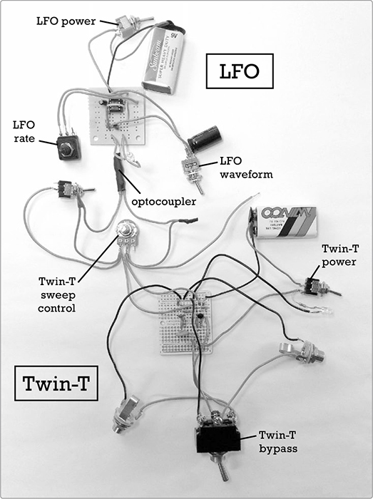
FIGURE 14-23: The finished guts of the Twin-T Phaser/Wah with LFO. The LFO is at the top, the Twin-T at the bottom, and the two are linked through the sweep-control pot in the middle.
Step 23 Now for the photoresistor-based faux-pedal wah controller. Cut, strip, and tin a 6-inch length of insulated wire. Solder one end to one of the legs of your photoresistor. Solder the other end of the lead to the open lug on the wah control switch, which is the SPST switch connected to lug 3 of the 50k ohm pot. Then, solder the free leg of the photoresistor to the open 6-inch lead from lug 2 of the 50k ohm pot.
Ta-da! You’re done building! In the next section, we’ll test the whole thing.
Make sure everything has fresh batteries and powers up on its own. Hook an appropriate instrument to your Phaser/Wah, hook the Phaser/Wah to your amp, and power everything up. With the LFO off and the photoresistor covered with something opaque—such as a ceramic coffee mug—the Phaser/Wah should function as it did in “Test the Twin-T Circuit” on page 257.
Now turn off the sweep-control pot by running it fully clockwise, and then activate the LFO. The filter effect should come in and out in sync with the blink of your LED. If it doesn’t, that might mean you installed the sweep pot backward. That’s fine. Just twist it fully counterclockwise instead of clockwise to let the LFO take over.
Set to square wave, the effect should cut in and out rather sharply, an effect most useful at relatively high speeds. Set to pseudo-sine wave, the filter should sweep in as the LED glows and then dims, an effect that’s most enchanting at slower speeds.
Finally, turn off the LFO and uncover the photoresistor. You should now be able to control the filter by covering and uncovering the photoresistor, exposing it to more or less light, for an overall effect similar to a traditional wah-wah pedal.
When your controls check out, mount everything in your enclosure. I prefer a nice large, flat cigar box to give me room for all my bells and whistles. For advice on choosing and modifying enclosures, see “On Enclosures” on page 214.
Most of the mounting process is pretty straightforward: keep the power and control switches and pots a fair distance from the big DPDT bypass switch so you have room to operate. Also, placing the input and output jacks on the sides of the box, as opposed to the lid, usually makes it easier to keep the cords out of your way.
The one tricky bit is mounting the photoresistor for the wah pedal. The photoresistor should be mounted on the outside surface of the enclosure, which is going to necessitate a little desoldering and resoldering.
To install the photoresistor, start by drilling a hole somewhere on your enclosure that’ll be convenient for toe-tap operation. (Figure 14-1 shows that I installed mine on the top of my enclosure, away from the other controls; it’s centered near the bottom edge of the box lid.) The hole needs to be slightly smaller than the head of the photoresistor. In most cases, drilling with a 3/16-inch or 1/4-inch bit is just right, although smaller photoresistors might call for an 1/8-inch hole. For truly huge photoresistors, you might be best off drilling two small holes, one for each lead.
If you’re using a metal-topped enclosure, insulate the leads on your photoresistor; a couple snips of shrink tube or a fold of duct or electrical tape should do. Now smear some silicone-based glue around the hole on the exterior of the case, thread the photoresistor leads through the hole, and press the resistor into place so that it faces outward.
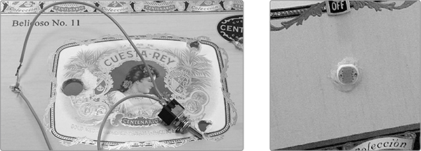
Let it dry for at least 30 minutes before resoldering the leads, and give it a full 24 hours to dry before putting the wah into action. (Smearing semi-dry silicone-based glue all over the light-sensitive surface of the resistor will hamper its operation.) Figure 14-24 shows the installed photoresistor wah pedal controller from the inside and outside.
FIGURE 14-24: An interior view of the photoresistor wah control installed in the lid of the enclosure (left). The switch activates the photoresistor wah. The photoresistor itself is soldered to the two visible leads. The exterior close-up (right) shows the photoresistor glued directly to the outside of the box lid.
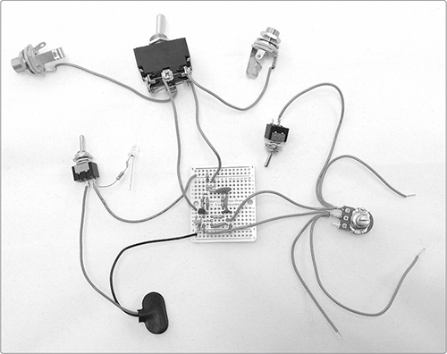
When you’re finished drilling holes, stuff the enclosure (see Figure 14-25). Make a point of securing the batteries and PCBs, since they are highly likely to bang around and cause hassles otherwise.
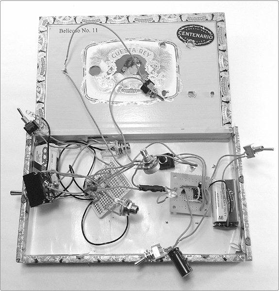
FIGURE 14-25: Stuffing the enclosure for the Twin-T Phaser/Wah
Like other effects, such as the Mud-n-Sizzle Preamp (Project 12), the Twin-T Phaser/Wah is pretty self-instructive: plug an instrument into the input, plug an amp into the output, and begin exploring the sounds you can coax out of your instruments and the filter. Let’s quickly run through the three modes in isolation.
Wah-wah mode Turn on the wah switch and then cover and uncover the phototransistor with your toe to produce a wah-wah pedal effect of the sort you might hear in a Hendrix or Hayes tune. How you play your instrument has a big impact on how these come across. For classic wakka-chikka effects, work the wah-wah pedal while muting the guitar strings. For “Voodoo Child”–style yowls, play longer single notes with a little bend to them.
Manual filter mode Filter sweeps are super common in dance and club music. It’s that whooshing effect, where the music seems to lose and then gain “presence” without changing volume. To do filter sweeps using the Twin-T Phaser/Wah, just switch off the LFO and photoresistor and then work the sweep-control knob back and forth manually (in other words, you create a filter sweep by sweeping the filter’s notch frequency).
With the LFO and wah off, you can also dial in a particular frequency and then leave the filter alone, emphasizing a sweet spot in your tone. This set-and-forget technique is a really common off-label use of wah pedals: Hendrix did it when he played the “Star-Spangled Banner” at Woodstock, as did Mark Knopfler on Dire Strait’s “Money for Nothing.”
Phaser mode As for LFO-controlled phaser effects, you’ll easily pick these out in pop recordings from the 1970s2 and modern electronica, but they’re also widely used to more subtle effect. Listen for phasers in the Sex Pistols’s “Anarchy in the UK,” which layers several guitars with phasers panned hard right and left. To use your phaser, switch off the photoresistor wah pedal and turn the sweep control fully clockwise. Then, turn on the LFO and select a rate and waveform that work for you.
Of course, you can also mix-and-match these modes. Get the LFO going and then occasionally override it on the fly with the sweep control or wah. Or dial in a sweet spot on the sweep control and then vary from that using the photoresistor wah. Or set a sweet spot and then occasionally activate the LFO to transform the mood of your jam. In addition to playing with different settings, experiment with placing the Twin-T Phaser/Wah in different positions in your effects chain, as it can behave very differently as its input changes.
One note for general use: our photoresistor wah pedal, being light dependent, is less precise than a traditional mechanical wah pedal and will need a steady light source in order to behave consistently—or, alternatively, it can be augmented with an unsteady light source in order to behave erratically, if that’s your thing.
This project is the most complicated so far in the book, which means there’s a lot of room for modification and improvisation.
For starters, here are some simple tricks to improve your sound. If you’re picking up radio broadcasts, baby monitors, or other RF interference, try running a ground connection from the common ground on the PCB to the metal enclosure. If you didn’t use a metal enclosure, you can add a ground plane by lining the bottom of your enclosure with a piece of thin aluminum cut from a disposable pie tin or catering tray—or you can even use a few layers of aluminum foil. Either solder your ground connection to that ground plane or bolt a ground wire to it. Place a layer of construction paper or self-adhesive contact paper between the ground plane and PCB to prevent short circuits.
If you find that hotter instruments or inputs are roaringly loud and seem little impacted by the Twin-T’s sweep, try cutting the power to the twin-T portion of the circuit. This kills the preamp but largely keeps the passive filter working. Another option is to break the ground between the instrument and effect. This option is especially effective with electronic instruments, like synths. To make this more convenient, consider adding a ground interrupt switch on the Twin-T Phaser/Wah’s input jack, as shown in Figure 14-26. To do this, install a regular SPST switch on the ground wire connecting the twin-T input jack to the circuit. When you open the switch, the ground on the instrument no longer connects to the twin-T circuit, significantly cutting the amplification while maintaining the effect.

FIGURE 14-26: A simple ground interrupt switch
In terms of purely fun mods, the most obvious place to start is with component values. The output cap can be increased up to about 10 μF. The higher the value, the more bass-heavy your output will sound, which can give a very different color to your tone. If you’re using electrolytic caps (anything over 1 μF or so will likely be electrolytic), connect the positive leg of the electrolytic cap to the circuit itself and the negative leg to the output jack.
You may also want to monkey with the matched capacitors and resistors in the twin-T filter section of the circuit. Each of the caps in the crossbar of the capacitor T should have about half the capacitance of the capacitor in the stem of the resistor T. In my design, for example, the capacitor T’s two crossbar caps are 0.0047 μF and the resistor T’s single stem cap is 0.01 μF. The matched resistors in the resistor T’s crossbar can go as low as 100k ohm. Using lower-value resistors will shift the effective range of the wah down into lower frequencies. The current design, with 470k ohm resistors in the resistor T’s crossbar, mostly affects higher frequencies.
As with the Mud-n-Sizzle Preamp (Project 12), you can boost this effect into something much more aggressive and distorted by replacing the single transistor in the preamp with a Darlington transistor pair. For details, flip to “Boost the Fuzz with a Darlington Pair” on page 216.
You could save space by omitting the bypass switch. This is especially handy if you decide to build the Twin-T Phaser/Wah into another instrument or effect. To skip the bypass switch, wire the input jack’s tip directly to the circuit’s input (at pad 1E on the AdaFruit PCB) and the output jack’s tip directly to the circuit output (pad 6J). Both jack’s ground lugs continue to go to the common ground rail. If this sounds confusing, just flip back to Figure 14-22; the detailed picture on the right shows where the audio in and audio out connect to the PCB.
The real obstacle to building a commercial-style wah pedal isn’t the circuit. The twin-T notch filter is a pretty easy build, and if you’d prefer a band-pass filter (the sort used in the very popular Cry Baby wah pedal), there are plenty of straightforward inductor-based wah circuits out there and many suggestions on how to scrounge up a suitable 500 millihenry inductor. Just Google inductor wah circuit and work from there.
The real trick is that darn custom-built, heavy-duty pedal enclosure and the beefy wah potentiometer. Fortunately, there are plenty of “broken” wah pedals out there in secondhand music stores, pawnshops, garage sales, message boards, and so on. Most of the time, these are broken because the circuit itself got trashed; leaky batteries, beers, and decades of abuse are frequent culprits. The pedal enclosure and wah pot are usually fine, ready for your circuit to move in, hermit-crab style.
To install your Twin-T Phaser/Wah in a pro enclosure, start by pulling out the dead wah’s guts: clip the leads to the dead wah’s potentiometer and discard everything else. Test the dead wah’s potentiometer with your multimeter. All that really matters is that the pot consistently changes resistance as you rock the pedal. Now snip off your Twin-T’s photoresistor and solder those two leads to the middle lug and one outer lug on the dead wah’s pot. Bolt this beautiful monster together, and you’re done.
It’s a pretty straightforward half-hour’s work, although you might need to get a little creative in order to accommodate all your pots and switches. Need ideas on how to accomplish this? Flip back to “Package Your Project” on page 110 and consider an add-on enclosure for this Frankensteinian phaserwahstrosity.
Now you’ve got something truly wicked-awesome: a fully custom, heavy-duty, heavy-metal wah-wah pedal with full filter-sweep and phaser capabilities. Rock on!