The Slinkiphone (Project 1) and Scratchbox (Project 5) hint at a fundamental truth of the modern age: there are lots of really neat sounds hiding inside your toys and consumer electronics. Cracking open cheap electronics and feasting on the sonic goo within is called circuit bending. This sort of exploration was pioneered by artist Reed Ghazala, the “Father of Circuit Bending,” who stumbled across his first bends as a teen in the mid-1960s. Ghazala has tirelessly promoted the creative potential of musically upcycling consumer electronics ever since. In this project, you’ll get your feet wet with three entry-level bends.
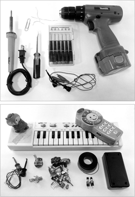
Thrift stores, garage sales, and remainder bins are full of electronic toys ripe for exploration. When choosing a toy to tweak, use only battery-powered toys, and keep an eye peeled for older toys. Older toys are usually built with largely generic components and offer more circuit-bending options than newer toys, which tend to offload almost all of their functions to purpose-built microprocessors. That said, bending new toys can still be quite fruitful. For example, most pip-squeak electronic toys—like those shown in Figure 7-1—can generate big, rich sounds with impressive bass, but their puny built-in speakers just aren’t up to the task. A little bending can unleash all that good noise.
FIGURE 7-1: A selection of circuit-bent instruments and toys. Note the black box on the keyboard and the new bits on the other three: the knobs, switches, and bare metal contacts allow us to tinker with the toys’ pitch and tone on the fly, while the jacks allow us to amplify the output (and, in the case of the megaphone, pump our own signal into the input).
* WARNING: Only bend battery-powered electronics! Household batteries are generally safe to work with: they’re small and supply relatively low voltages and currents. For example, a 9-volt battery will reliably supply under 100 mA and shouldn’t hurt you (unless you try to swallow it, I suppose). In contrast, the AC electricity available from your wall outlets is dangerous, offering dozens of times as much voltage and over 100 times the current—120 volts and 10 to 15 amps. Wall current can easily burn your house down and will certainly kill you given the opportunity. Nothing in this book is intended to ever encourage you to work on any electrical device that plugs into the wall!
Hear my circuit-bent keyboard in action in the samples at http://www.nostarch.com/jamband/.
Build Time
 About 30 minutes to an hour, depending on the toy and amount of modification
Tools
A standard soldering kit (See page 340.)
A selection of screwdrivers (If you don’t already have them, I suggest a set of jeweler’s screwdrivers, which usually includes #0 and #1 Phillips and 1.4 mm, 2 mm, 2.4 mm, and 3 mm flathead drivers.)
A small flathead screwdriver for prying open plastic cases
Several sets of jumper clips (You can use insulated test leads, which look like tiny jumper cables. Pricier mini-clip hook-style jumper wires are even better.)
An electric drill with bits (This is for modifying the toy’s case to accommodate new jacks and switches.)
Supplies
A battery-operated toy or instrument you’d like to vivisect
Two normally on momentary pushbutton switches, also called normally closed SPST switches (For more on switches, see “Switches” on page 338.)
A 1M ohm variable resistor (Variable resistors are also called potentiometers or pots; see “The Gory Details: Audio Taper vs. Linear Taper” on page 327.)
A fistful of other resistors, potentiometers, switches, brass screws, metal knobs, and so on
A 1/4-inch mono phone jack, also called a guitar jack
24-gauge insulated hook-up wire (22-gauge speaker wire is fine, too. It’s stranded like hook-up wire, only slightly thicker.)
Small boxes to accommodate the extra jacks, switches, and pots you’ll add to instruments (Any thin-walled plastic box will do; hobby shops often carry a variety of “enclosures” and “project boxes,” like the one attached to the keyboard in Figure 7-1. See “On Enclosures” on page 214 for more information.)
Two alligator clips (The ones shown in Figure 7-12, often called mini-hook clips, are much easier to use when clipping into commercially produced circuits. Those pictured are American-made “E-Z-MINI-HOOK TEST CONNECTORS” from E-Z-HOOK, Digi-Key parts #461-1013-ND and #461-1014-ND.)
22- or 24-gauge bare bus wire (This is uninsulated solid core wire. Because you need only a few little snips of bus wire for this project, you can get away with using a scrap of wire, a leftover bit snipped from a component lead, or even a piece of a paper clip.)
FIGURE 7-2: Tools and supplies
Once you have a few toys picked out, we’ll modify the output by adding a 1/4-inch jack and optional momentary mute button, use resistor-based bends to safely monkey with the circuit’s internal clock, and add a power reset to set the stage for advanced circuit exploration. We’ll finish up with a brief discussion of how to package a finished circuit-bent project.
Most toys, especially newer ones, have little spare space inside to accommodate new jacks, switches, and variable resistors, so the most important preparation is to consider how to package all that when you’re done adding new functions. Final packaging can be tricky, but it’s far from impossible; think of it as another outlet for creativity. Also, keep in mind that there’s nothing stopping you from adding off-board expansion modules or entirely repackaging the toy’s electronics in a larger case.
While you’re pondering your packaging options, pull the batteries out of your toy and remove all the screws you can find. Remember to look for screws hiding under stickers and in the bottom of the battery compartment. Then, pry open your toy’s case and determine whether you’re dealing with an old or new toy. If you’re unsure, check out Figure 7-3. The left panel shows a portion of the guts from a 1980s electronic toy keyboard; the right shows the entire circuit board from a newer McDonald’s Happy Meal freebie toy (specifically, a 2010 Alvin and the Chipmunks talking Theodore).
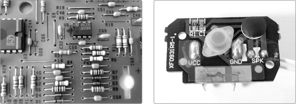
FIGURE 7-3: The older circuit board (left) has many large, easy-to-identify components. The modern toy’s circuit board (right) is much smaller (the entire board is smaller than my thumb) and has few components, which are harder to distinguish.
The older toy is comprised of many generic, discrete components1 that you’ll recognize from building your Droid Voicebox (Project 6) or other electronics projects: resistors, capacitors, variable resistors, diodes, LEDs, and integrated circuits (ICs). The new toy, on the other hand, has few recognizable components and instead sports that mysterious black blob (in this case, it’s in the upper-right corner). That blob hides a single, highly specific microprocessor that replaces most of those discrete parts. Newer toys usually rely on such black-blob chips. To add to the challenge, the few discrete components in these newer toys will usually be very small surface-mount components, such as resistor R1 and capacitor C1 in Figure 7-3, as opposed to the standard components you’ll buy for projects in this book. Surface-mount components are harder to tell apart than standard components and, owing to their small size, are more of a pain to work with. That said, even on newer toys with small circuits composed of surface-mount components, changing up the output remains a straightforward operation that greatly expands the toy’s audio palette.
I strongly advise adding 1/4-inch jacks to every toy. I’ve regularly been delighted by the breadth and depth of sounds even the junkiest toy has to offer once it’s properly amplified or pumped into commercial or homebrew effects. I also strongly advise using a high-quality jack: the jack is going to get jerked around a fair bit, and something nice, like a Switchcraft, will put up with that for many years. The cheapest of cheap jacks—which tend to be standard on consumer-grade electronics and even midgrade guitar amps from big-name manufacturers—can start to get loose and noisy after just a few months of regular use. Very annoying. A Switchcraft will stay sure and steady for decades.
In this section, you’ll work with two kinds of mono phone jacks: normal and switch jacks. The normal mono jacks, shown at the far left of Figure 7-4, will be familiar if you’ve ever seen or handled a guitar, amplifier, or stomp box. The switch jacks, shown in the middle and on the right, are a little special. When nothing is plugged into a switch jack, the signal goes to the device’s built-in speaker. When you plug something in, the internal speaker is disconnected, and the signal is routed instead to the external amp. If you’re planning to replace the toy’s original speaker altogether, use a normal mono jack. If you want to keep the original speaker and don’t care that the built-in speaker makes sound even when the toy is plugged into an amp or effect, then a normal jack is still fine. But if you want the toy to automatically mute the built-in speaker when you plug into your amp or effect, then you want to install a switch jack.
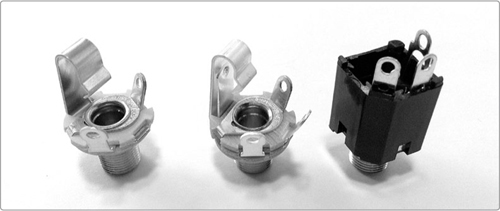
FIGURE 7-4: A standard mono jack (left), a generic switch jack (center), and a Switchcraft 112AX switch jack (right)
Step 1 Choose a jack. For plain old jacks, I’d go with the Switchcraft L11, shown at the far left of Figure 7-4. It’s Digi-Key part #SC1085-ND or Mouser part #502-L-11. (Always check both, as there can be a pretty big price difference, especially once you work in shipping and handling.) The middle jack in Figure 7-4 is a Switchcraft 12A, which is the switchable version of the standard Switchcraft mono jack. This open-style switch jack is nice because its internal mechanism is entirely visible, making it a little easier to understand if you’re new to electronics. Its only drawback is that it looks an awful lot like a standard mono or stereo jack. If you have a jumbled box of mixed jacks (as I do), it’s easy to miscount and get halfway through a project before realizing you don’t have the jack you thought you had. For that reason, my preferred switch jack is the partially enclosed Switchcraft 112AX, shown at the far right of Figure 7-4. It’s the same jack used in the Plasti-Pickup (Project 2), Digi-Key part #SC1316-ND or Mouser part #502-112AX, and it’s very easy to distinguish from mono and stereo jacks.
* NOTE: Steps 2 through 4 describe how to add a plain old jack, while Step 5 describes how to add a switch jack.
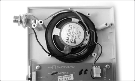
Step 2 Decide whether you want to keep your toy’s existing speaker or amputate it. If you choose to lose the existing speaker, then this mod requires only the two steps shown in Figure 7-5: snip off the speaker, solder one wire to each of the two lugs on a standard 1/4-inch jack, and you’re done. The black speaker wire traditionally goes to the jack’s ground lug and the red wire to its tip, but that rarely makes any difference in these situations. (If you have no idea what the tip and ground are on a mono phone jack, flip to “Quarter-Inch Phone Plugs and Jacks” on page 337, where they’re illustrated. If this is all new to you, see “Soldering” on page 346.) If you’ve decided to keep the speaker, move on to Step 3. If you’d like to add a momentary mute, skip to Step 4.
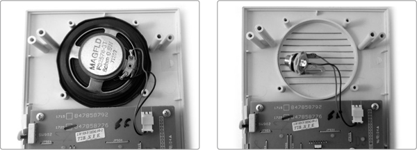
FIGURE 7-5: The unmodified toy with speaker in place (left); an amputated speaker replaced with a jack (right)
Step 3 If you want to keep the original speaker, the quick-and-easy solution is to jumper a jack in, as shown in Figure 7-6. To accomplish this, just cut two lengths of insulated wire, strip and tin both ends of each, and solder one wire to each lug on the jack. Now, solder one wire to each of the two terminals on the speaker. On the upside, this approach is quick and easy, and you retain the ability to play anywhere while adding the ability to harness amps and effects. On the downside, even when you’re plugged into an external amp, you’ll still have the built-in speaker making noise, which might prove annoying, especially if you use mics to isolate your various instruments for recording. If this sounds annoying, flip to Step 5. Otherwise, you’re done!
FIGURE 7-6: A “jumpered” auxiliary output jack
Step 4 Adding a pushbutton momentary mute allows you to quickly cut the signal to the speaker and output jack. Just snip the positive speaker wire, which is usually red and is often connected to a + sign on the circuit board, the speaker itself, or both. Then, install a normally closed—that is, normally on—pushbutton SPST switch between the circuit board and the speaker and output jack (see Figure 7-7). When you hold the button down, the output is silenced. Release the switch, and the speaker immediately comes back online.
* NOTE: If the board and speaker are unmarked and the wires are otherwise identical, don’t sweat it. Just choose one wire to consider positive and stick with that. “Positive” and “negative” are almost always arbitrary distinctions when it comes to small speakers in battery-powered toys.
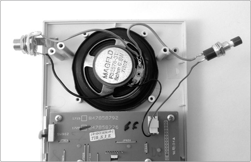
FIGURE 7-7: An auxiliary output with a momentary mute
A mute offers a lot of neat sonic possibilities, allowing you to chop and punctuate the toy’s noise. For example, rhythmic momentary muting is a key to the stuttery gate and transform effects popular in electronic dance music. Even if you don’t choose to add an output jack, a momentary mute is still a fun mod for any electronic noise toy.
You should be done installing your plain jack at this point, so either move on to the next mod, “Explore Resistor Bends” on page 104, or read on through Step 5 to learn how to add a switch jack.
Step 5 If you don’t want the internal speaker to play at all times, use a switch jack. On the partially enclosed Switchcraft jack I’ve specified, the corner lug2 is the ground connection, and it makes contact with the barrel, rather than the tip, of the plug. The lug farthest from the ground lug connects to the jack’s tip and carries the audio signal. The middle lug connects to the internal switch.
To wire this switch jack, first snip the positive speaker wire in half. Solder the lead connected to the board to the tip lug of your jack. Then solder the lead connected to the speaker to the middle lug. Solder a separate insulated wire from the jack’s ground lug to the other lug on your speaker, as shown in Figure 7-8. Note that this switch jack layout—with the ground and tip opposite each other and the switch connection in the middle—is likely not universal. To determine which lug is which on your jack, either check the datasheet (the site where you ordered the part should have it posted in the online product listing) or do a little guessing and checking. You can also add a momentary mute here, if you like. The procedure is exactly the same as it was with the plain old jack, outlined in Step 4.
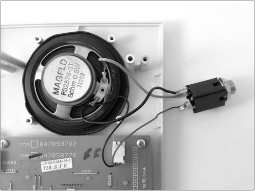
FIGURE 7-8: A finished switch jack output
Resistor bends are a good place to start because they’re relatively easy to find and install and have a low likelihood of destroying a circuit.
Step 1 Now that we’re getting down to the nitty-gritty of circuit bending, select a toy to explore for good resistor bends. Anything that makes a noise will do. Pop open a few candidate toys, and you’ll immediately notice the difference between new and old electronic toys, as I described in the introduction of “Three Basic Circuit Bends” on page 98.
Step 2 Start by finding the resistors. With older toys, the resistors may be a touch larger or smaller than those you buy at your local hobby shop, but they’ll still look a lot like what you’ve seen in this book so far: an oblong body (usually tan, sometimes blue or green) marked with four stripes, with wire leads protruding from either end. You may see small traditional resistors in newer electronics, too, but more often, the resistors will present themselves as flat black rectangles with a white stripe at either end; sometimes these surface-mount resistors are numerically coded, and sometimes they’re just plain black. Either way, you’ll almost always find their positions on the circuit board marked with an R followed by a number (see Figure 7-9 for an example of both old-toy and new-toy resistors).
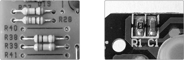
FIGURE 7-9: On the left, a portion of an older toy’s circuit board featuring four resistors. On the right, a close-up of a newer toy’s circuit board, highlighting a surface-mount resistor next to a surface-mount capacitor. Note the R labels on both circuit boards, denoting the placement of resistors.
Step 3 Once you’ve found some promising resistors—the ones nearest the ICs or adjacent to trim pots (see Figure 7-13) are often good ones—start poking around for fun bends. Load the batteries back into your electronic toy and power it up. Get the toy making noise and then use your fingers to bridge the leads on a single resistor.
* WARNING: Poking the circuit board while it’s powered is safe only if the toy is battery powered. This is never safe with anything that is, or can be, plugged into the wall!
I’ve shown several techniques in Figures 7-10 and 7-11. Some folks, especially older folks, may need to lick their fingers for this to work (older skin tends to offer more resistance than younger skin). Repeat until your poking makes something interesting happen to the sound: it might get louder, softer, faster, slower, higher pitched, or lower pitched. You might also hear rhythmic palpitations, a crazy squeal, or looping; a sample might unexpectedly play or repeat; and so on. Usually, pressing harder will make it happen more.
For smaller resistors, just one finger should work well. If the resistor is larger and your hands are small, you may need two fingers, as shown in Figure 7-11.
You’ve gotten a noise! Rad! But what the heck just happened? As I described in the Droid Voicebox (Project 6), your skin is a resistor. In this case, that skin resistor is being used to create a short circuit, temporarily overriding the factory-installed resistor soldered to the circuit board—that is, a resistor bend. If you press lightly, it will offer around 3M ohm of resistance. As you press harder, you lower the resistivity down to just a few hundred ohms. Using your skin as a variable-resistance probe is both cheap and easy, allowing you to quickly move through a circuit and find fun sounds.
If you’re having trouble making good contact in a given spot, hold a pair of bare wires between your damp thumb and forefinger, making sure that the wires don’t touch; you need to force them to use your skin to complete the circuit (see the right image in Figure 7-10). Squeezing the two wires will decrease resistance, just as pressing harder on the board does.
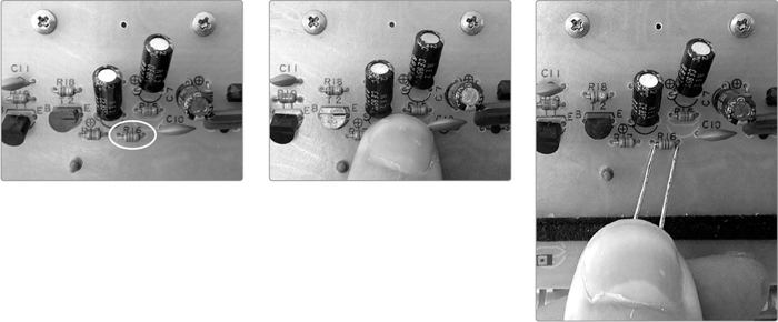
FIGURE 7-10: Poking around for a fun bend: my target is the small resistor labeled R16, shown in the far left panel. Try poking small resistors with one finger (center) or a pair of bare wires (right). Note that the pair of bare wires—which are two straight pieces of paperclip—are not touching: my thumb is acting as a resistor bridging the gap between the wires.
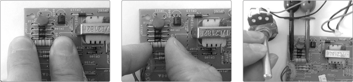
FIGURE 7-11: Poking around for a fun bend on a larger resistor: using two fingers in two different positions (left and center) or a clip-on pot (right)
Of course, sticking a wet finger into a live circuit is a decidedly maladaptive practice, so if you’re not cool with trying it, just rig up a little clip-on variable resistor, as shown in Figure 7-12. A 1M ohm resistor is a good size here. All you need to do is solder one clip lead to lug 1 of the resistor and the other to lug 2. With the pot twisted fully counterclockwise, it will offer 1M ohm of resistance. As you turn it clockwise, you reduce the resistance. The clip-on variable resistor is a nice tool because it allows you to dial in precise resistances. If you hit a sound you really love, you can unclip the resistor and use your multimeter to measure the resistance currently dialed into the 1M ohm pot. When you go to make your bends permanent in Step 5, you can wire in a resistor of that value and thus rig up pushbutton access to that new sound you discovered.
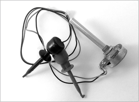
FIGURE 7-12: A clip-on variable resistor
Poking around your circuit board while it’s on will generally uncover one of three types of resistors:
A volume-controlling resistor. Bending these resistors will either raise or lower the volume of some aspect of the toy’s sound. Zeroing in on these resistors sometimes make it possible to separate a voice from a background rhythm or to make some part of the mix in prerecorded music more prominent.
A resistor that sets the clock speed for the toy’s IC. Clock speed determines how often a chip repeats a function or how fast it executes an instruction, and finding a clock-speed resistor is the jackpot. Bending it will change the speed or pitch (or both!) of some aspect of the sound, possibly for multiple sounds or even all sounds the device makes.
A resistor that causes a glitch. In this case, a glitch is any sort of crazy sound that you like that isn’t part of the machine’s usual repertoire.
Step 4 Check for board-mounted variable resistors, like those shown in Figure 7-13. Variable resistors are another very promising source of bends, especially on older toys. These small potentiometers are called trim pots or trimmers, and they are often used to fine-tune, or trim, a toy’s speed or pitch. Trim pots are usually so small that they don’t even have knobs (see Figure 7-13, left). Instead, they’re adjusted using a small screwdriver or Allen wrench. Fiddle with them! You’ll likely get effects like those enumerated earlier. You can remove these trim pots and replace them with large potentiometers mounted on the toy’s case so that you can easily tweak them while playing. You bought that toy, so break it however you deem fit. You can also probe these trimmers with the same methods I described in Step 3. Because a trim pot frequently has three legs instead of just two leads, there are even more possibilities to explore.
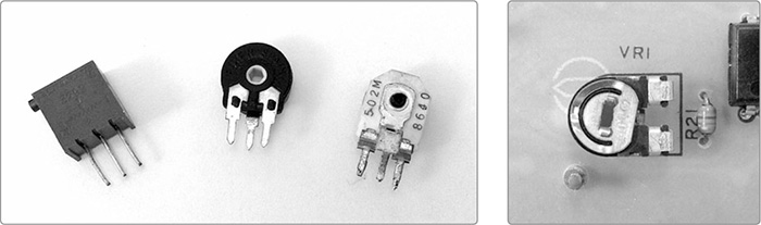
FIGURE 7-13: Several styles of trim pots (left) and an in situ trim pot (right)
Now it’s time to make your resistor bends permanent by adding a switch, knob, or some other extension that’ll allow you to easily tweak the resistance whenever you want.
Step 5 Start by adding leads to the resistor you want to bend. Just cut a pair of insulated wires long enough to reach from the circuit board to wherever you’re going to mount the switch or knob on your case. Then, strip both ends of each wire and tin both ends. Now, solder one wire to each side of the target resistor, as shown in Figure 7-14.
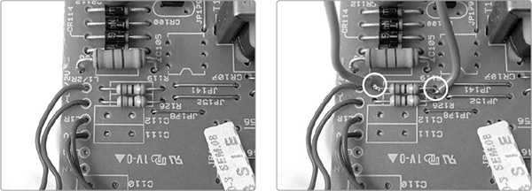
FIGURE 7-14: Adding leads to the resistor—before (left) and after (right)
Step 6 Add the control for your bend. You have three options: body contacts, a potentiometer, or a switch. Body contacts are circuit bending’s most emblematic control, formalizing your temporary “finger in the circuit” maneuver. They can be as simple as the “deely-boppers” sticking out of Theodore’s head in Figure 7-19, which are just the bare leads from Step 5. Usually, however, they’re a pair of conductive pads or studs bolted to the outside of your bent toy (see Figure 7-15). A quartet of body contacts are prominently displayed on the add-on enclosure bolted to the left side of my keyboard in Figure 7-21 (right).
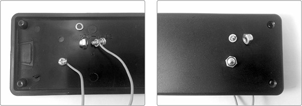
FIGURE 7-15: A set of body contacts viewed from the inside (left) and outside (right)
To make body contacts, I like to use #6 brass acorn nuts mounted on #6 machine screws. A couple of washers on the machine screw will help ensure a good contact between your lead from Step 5 and the nut. Body contacts offer very expressive bend control and, because different individuals’ skin will put up different amounts of resistance on different days and in different conditions, generally make for unique improvisations.
On the other hand, if you’d like the reliability and convenience of dial-in control, you could connect your leads to a potentiometer instead of body contacts. Select any variable resistor; 1M ohm is a good place to start, as it approximates the resistivity of your skin, but experiment with several values to see what results in the sounds you want. Solder one of the two leads you added to the toy to the middle lug of the variable resistor and the other to either of the two outer lugs (see Figure 7-16).
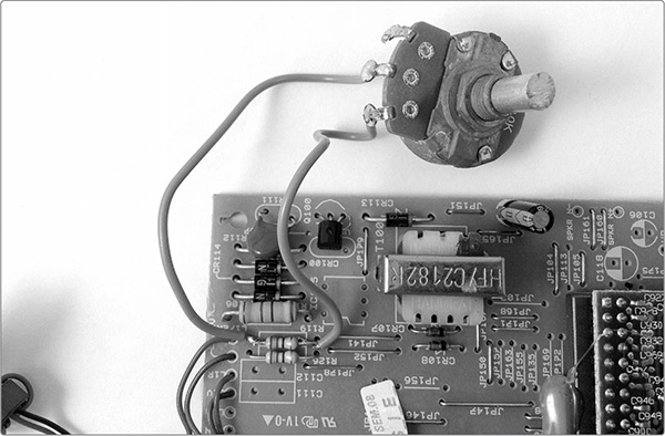
FIGURE 7-16: A potentiometer bend controller
Finally, some bends, especially glitches, are most fun at full warp with zero resistance. In these cases, just add a small switch—either pushbutton or toggle, whichever you prefer. Solder one wire to each lug, and you’re ready to go (see Figure 7-17). If you want to insert a specific resistor value in series here—in order to capture the just-right squeal you found with your clip-on variable resistor in Step 3 on page 104—do so by soldering one resistor lead to the switch lug and the other to one of the leads.
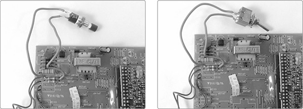
FIGURE 7-17: Controlling a bend with a momentary pushbutton or toggle switch
Of course, circuit bending doesn’t have to be limited to resistors or even to single components. The next logical step is to use your fingers to test for bends on capacitors or diodes, or even to create bends between adjacent components. Bends that run resistor-to-resistor, resistor-to-cap, IC-to-IC, or anything-to-ground or sprawl among a slew of different points on the board are all possible—and sometimes pretty rad.
* WARNING: Messing with ICs is more likely to fry your circuit. Proceed with caution!
If you’re going to branch out beyond the simple single-resistor bends you’ve done so far, you want to add a power reset.
More advanced bends have a higher likelihood of causing the circuit to freak out and lock up, and it’ll take a hard reset to get it running properly again. Adding a reset switch to the power supply lets you avoid constantly popping out the batteries to get the toy working again. A reset switch also makes it possible to create some neat effects by stuttering the power supply.
Step 1 Find the positive power connection in your toy. This will almost always be red and very often connects to a + sign on the circuit board.
Step 2 Cut this lead, strip both ends, and tin them, as shown in Figure 7-18 (center).
Step 3 Solder one lead to each of the two lugs on a normally closed pushbutton SPST switch (just like the one you used as a mute switch in Step 4 on page 102).
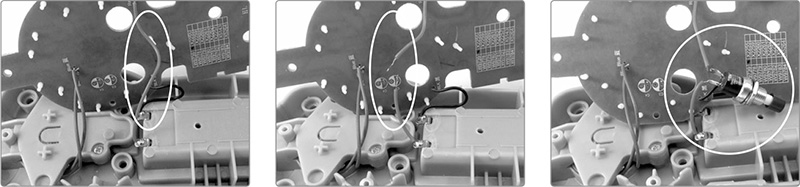
FIGURE 7-18: Installing a momentary power reset switch. Find the power connection (the long wire in the middle of the left image), cut it (center), and solder in the switch (right).
Step 4 Ta-da! You now have a power reset switch. If the toy locks up or goes nutsy, push the switch for a few seconds to disconnect the power from the circuit. Then, release the reset button and carry on. You can also occasionally use the power reset musically, perhaps in combination with the mute button, to chop up and recue sounds, samples, and rhythms in new ways.
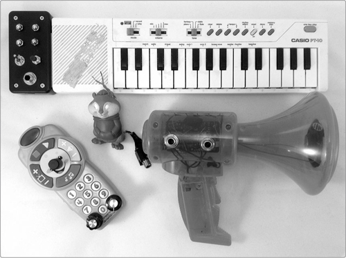
The final step is always to put your toy and its new circuitry all together in some usable format. Some examples of finished circuit-bent toys are shown in Figure 7-1. Let’s look at two of these in detail, starting with lil’ Theodore, shown before and after in Figure 7-19.
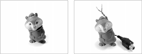
FIGURE 7-19: Talking Happy Meal Theodore, before and after bending (You can see his unmodified brain on the right of Figures 7-3 and 7-9.)
As you can see in Figure 7-3 (right), talking Theodore is a thoroughly modern toy: his brain is a highly specialized custom IC supported by just two off-chip parts: a capacitor and a resistor. But that resistor sets his clock speed. Removing the original resistor and replacing it with a pair of body contacts, which stick out of his head like antennae, gives you full control of the lil’ guy’s pitch and rate. With the body contacts, you can make him groan like a creeping glacier or buzz and chirp at hyperdrive superspeed (even by chipmunk standards). I added an auxiliary jack, too, so I can pump his vocals through effects pedals. Theodore’s output was so loud I added a 1M ohm resistor to the auxiliary output (see the detail in Figure 7-20). It’s not unusual to have to add a buffer resistor when you bend freebie promo toys because they tend to be very loud, even on their tiny built-in speakers.
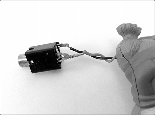
FIGURE 7-20: Detail of Theodore’s output jack, which needed a pretty large buffer resistor to tame his terrible cackles
By way of contrast, the Casio PT-10 keyboard, shown in Figure 7-21, is a more traditional circuit-bending subject. Dinky little 1980s toy keyboards of all stripes are the circuit-bending gold standard, in my humble opinion.
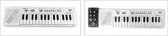
FIGURE 7-21: A vintage Casio keyboard untouched (left) and fully bent (right)
To accommodate the keyboard’s new electronics, I bolted an add-on enclosure to the left side. The add-on enclosure sports a 1/4-inch auxiliary jack at the bottom, just like Theodore, so the keyboard can easily be amplified or fed to effects. This one didn’t need a buffer resistor, as the volume level was reasonable to begin with.
Directly above the output jack are two switches: a pushbutton and a toggle. The pushbutton is a mute, and the toggle switch is a hyperdrive. The hyperdrive bridges the keyboard’s main clock resistor, in essence reducing the resistance to zero at that point in the circuit. This sends the keyboard’s preset voices and rhythms into whirring paroxysms of chiptunery. Above the mute and hyperdrive switches, I added four brass acorn nuts. These are body contacts connected to the resistor and trim pot that regulate the clock speed. Touching them individually or in combination changes both the pitch of the notes being played and the tempo of the built-in drum machine.
Of course, these are just a couple of ways to package these projects. I could have gutted lil’ Theodore and stuffed his electronics into an old teddy bear, a decorative gourd, or a candy tin. With a little care, I probably could have mounted all of my jacks, switches, and contacts into the PT-10’s original plastic housing; pulled the whole thing apart and installed it in an antique jewelry box; or wired it to the keys of a broken-down upright piano. However you choose to mount your electronics is awesome, because it’s yours. Now go out and share that awesome with other folks!
If you’ve gone so far as to make one or more of these instruments, then I’m sure you’ve already started to discover the ways in which they can make the sorts of glitch-punky jazz-noise you crave. But I do have two quick notes.
First, if you haven’t already done so, flip to “Playing the Scratchbox” on page 67. The advice there on using a momentary mute to sculpt sound—including transforms and gate effects—holds here and should help you start working your mute to musical effect.
Second, in all this prodding and soldering, it’s easy to lose track of the strictly mechanical bends you can do while playing. Almost any toy instrument can be made infinitely more interesting by using your cupped hand to muffle, wah-wah, and warble its built-in speaker. You could even go one step further and employ an improvised horn-player’s mute, like the plunger mute I talked about in the Elephant Trumpet’s “Tips, Tricks, and Mods” on page 35.
Along the same lines, consider converting the toy’s small internal speaker into an ad hoc compression driver, like the one we built for our Droid Voicebox (Project 6). This drifts a bit past playing style and into an actual mod, but it can make your hacked toys really sing.
Circuit bending is entirely an art of tricks and mods, so the one tip I have to add here is: don’t feel limited to just making new short circuits within an existing toy. Consider grafting your own homebrew circuits onto the factory-made ones. The Mud-n-Sizzle Preamp (Project 12), Twin-T Phaser/Wah (Project 14), and the filters and effects included in Appendix B are all good candidates for such surgery.
The Universal LFO (Project 13) is a good option, too: its two control leads are the legs of an automated variable resistor. Solder one control lead to each of the leads you added to your toy’s target resistor, and you can automate that bend or glitch, creating a wide variety of looping backup rhythms, warbling tones, slowsweeping filter effects, and not-even-God-knows what else.
If you’ve enjoyed this brief excursion digging into abandoned technologies and making them do new and unintended things, then do yourself a favor and invest in a multi-bit security driver set. This is a full set of screwdriver bits that includes all of the most popular odd-shaped bits that manufacturers use to discourage you from opening things up: triangles, asterisks, Torx, “tamper-resistant” Torx Plus, and so on. I own the generic 100-piece security bit set, shown in Figure 7-22, and have never regretted that $16 investment.
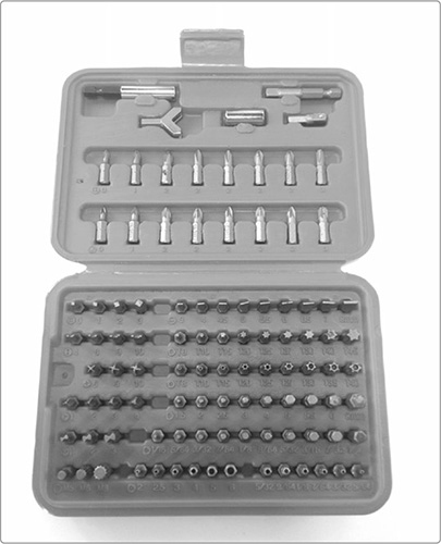
FIGURE 7-22: A generic 100-piece security bit set
If you want to learn more about circuit bending, there are two books I’d recommend. First, Reed Ghazala’s Circuit-Bending: Build Your Own Alien Instruments (2005) is a fun read for those interested in one man’s experience of the development of modern electronic music, and it includes detailed instructions on bending a set of popular musical toys. Second is Nicolas Collins’s excellent Handmade Electronic Music: The Art of Hardware Hacking (2006), which includes a section on circuit bending as well as tons of other great projects and ideas. It’s a vital resource for any electronic tinkerer drawn more to exploration and expression than rigorous electrical engineering.