Hip-hop turntabalism arose from folks abusing their LPs and record players in an age when most casual music listening was done via cassette. Now that we’re two iterations of musical media down the road, it’s high time to bust up your old tape deck and find some new sounds.
A tape deck is actually a relatively simple device built around an amplifier hooked to a fairly sensitive electromagnetic transducer, a component that translates variations in a magnetic field into sound. With a little soldering, you’ll be ready to coax a whole host of old-skool skritches and scratches from expired credit, gift, and loyalty cards.
Nearly any cassette player will work for this project: you could use a Walkman or a boom box, with or without a recording function—even an old car stereo would do the trick. It’s totally fine, even preferable, for the tape deck to be “broken” because the part we want—the transducer itself, called a tape head—is most likely intact. If you happen to choose a working tape deck with a built-in speaker, and you don’t wreck it too badly while extracting the tape head, you can convert it to a quick-and-dirty amp for projects in this book or even “real” guitars and other instruments you have kicking around.
Behold the Magnetic Musicassette!
The cassette tape—christened the Compact Cassette by Philips when they released it in the United States in 1964—is essentially a miniaturized reel-to-reel setup, and it works along the same principles. A strip of plastic tape coated in ferric oxide (laboratory-grade rust, which is magnetic) runs at a constant speed across a tape head. During the recording process, an audio signal is pumped into the head, which imparts a magnetic field of varying intensities to the tape, analogous to the varying intensities of the sound waves. During playback, the moving magnetic tape induces its fluctuating magnetic field in the play head. An amplifier built into the cassette player boosts this signal and sends it to a speaker, which reproduces the original audio.
Although their fidelity was relatively poor, these so-called Musicassettes were the dominant medium for prerecorded music for about two decades. Their portability, convenience, and relative indestructibility—especially when compared to vinyl records or early compact discs—trumped audio quality. The format itself was designed from the ground up to make both playback and recording cheap, easy, and highly portable, which inevitably led to the folk art of self-expression via mixtape. The longevity of the mixtape highlights the utter absurdity of modern patent trolls claiming they invented “playlists” a good decade after teens across America agonized over whether Bonnie Tyler’s “Total Eclipse of the Heart” should be followed by Whitney Houston’s “How Will I Know” or Kenny Loggins’s “Highway to the Danger Zone.”
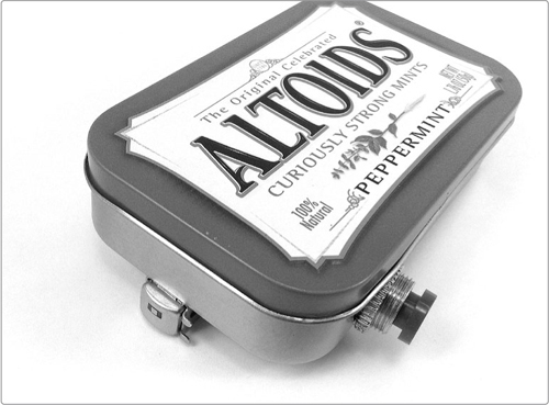
The finished Scratchbox is shown in Figure 5-1. Hear samples at http://www.nostarch.com/jamband/.
FIGURE 5-1: The finished Scratchbox
Build Time
 About 30 minutes
Tools
A standard soldering kit (See page 340.)
An electric drill with bits (You’ll probably need a 1/2-inch or 3/8-inch bit, a 1/4-inch or 3/16-inch bit, and a 1/16-inch bit.)
Needle-nose pliers
A set of small Phillips-head screwdrivers for disassembling the cassette player (Often called jeweler’s screwdrivers, these little guys are required equipment for voiding warranties on modern electronics.)
A small flathead screwdriver for prying open plastic cases
Supplies
Any old audio cassette player
A stack of old credit cards, gift cards, loyalty cards—anything with a magnetic stripe
A 1/4-inch mono phone jack, also called a guitar jack
A small enclosure (Metal is fine here; I used a standard Altoids tin. See “On Enclosures” on page 214 for more options.)
24-gauge insulated hook-up wire (22-gauge speaker wire is fine, too. It’s stranded like hook-up wire, only slightly thicker.)1
(Optional) Any normally on momentary pushbutton switch, also called a normally closed SPST switch (For more on switches, see “Switches” on page 338.)
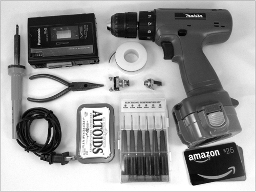
FIGURE 5-2: Tools and supplies
Step 1 Explore your cassette player. Every tape deck is different, and there’s really no map to this country, so start with some preplanning. We want to pull out the playback head, or play head (circled in Figure 5-3), which is usually secured to the cassette player’s carriage from the front by two screws. In many cases, you can remove the player’s door and have access to these screws, but you might have to at least partially disassemble the cassette player. Most players will have a set of Phillips-head screws on the back or bottom; remove every screw you can find. If you’re dealing with a boom box or tabletop model, pull off any little plastic feet; there are often screws hiding underneath. Once you’ve pulled out the obvious screws, try to force the case open. You’ll probably need to slide a flathead screwdriver into the seam and twist to break any adhesive used to seal the case in the factory.
* WARNING: Be careful not to cut yourself! A flathead screwdriver seems innocuous, but with a little muscle behind it—like when you’re trying to force apart a recalcitrant cassette deck case—it can easily slash and pierce you. Don’t become a statistic!
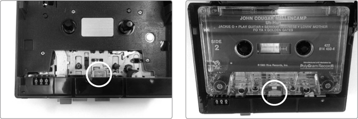
FIGURE 5-3: The elusive play head is circled. On the right, notice the same tape deck from a different angle (including a period-appropriate cassette, for reference).
Step 2 Extract the play head. Once you get inside the cassette player, you’ll find one or two tape heads. The one you want for this project is the play head, which will be all metal and centered. (The other, which is probably mostly plastic, is the erase head; in Figure 5-4, the play head is circled and the erase head is squared.) You’ll find the play head held in place by a pair of small Phillips-head screws and soldered to two or four wires. Loosen the screws, saving them for later, and clip the wires.
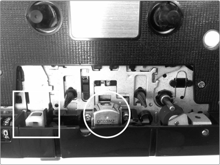
FIGURE 5-4: Play head (circled) and erase head (boxed)
Building a Tape Deck Amp
If your tape deck has a built-in speaker and still basically works after its surgery, you might as well make it into a spare amp. You just need to grab another 1/4-inch jack and solder it to those wires you just clipped from the tape head, one wire to each lug (as shown in Figure 5-5).
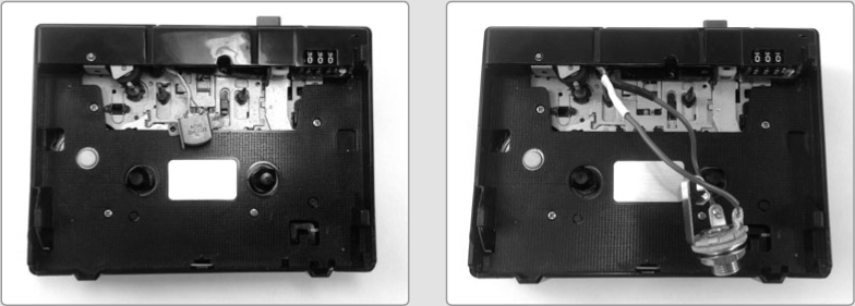
FIGURE 5-5: Making a tape deck amp: before (left) and after (right). I reinforced the connections to those dinky little play-head leads with shrink tube. This particular Walkmanesque recorder has a built-in speaker on the back.
If your tape head has four leads, like the one in Figure 5-11, try wiring both the left wires to one lug and both the right wires to the other. It shouldn’t matter which pair goes to which lug on the jack, although it’s hard to be certain. There are lots of half-broken tape decks in the world, and I’ve mucked around with only a very small percentage. If your first wiring doesn’t work, swap ’em, or try just using a single wire from each pair. The worst-case scenario is that something mostly broken becomes completely broken. At that point, you can just tear out the speaker and use it in a new amp, such as the “Dirt-Cheap Amp” on page 363.
To use your tape deck amp, power up the tape deck, plug in your instrument, and press play. FYI, these amps can be loud; the signal coming from a cassette tape is pretty low, so tape decks normally have beefy amps. The upside is that if you crank it up, you can often get rad, crunchy British Invasion distortion.
Gutting a Walkman or other speakerless tape deck? Don’t fret; you can use the same trick to transform it into a cheap-and-dirty preamplifier. (There’s more on preamps in “Tips, Tricks, and Mods” on page 69.) When building a Walkman preamplifier, the new 1/4-inch jack is your input, and the original headphone jack built into the unit is your output.
Step 3 Prepare your hook-up wire. Cut one 6-inch length of wire and two 3-inch lengths. Strip and tin both ends of each wire (refer to “Soldering” on page 346 if you need a refresher). If you’re leaving out the switch, then just prepare two 6-inch lengths of wire because you’ll be wiring the play head and jack directly to each other.
Step 4 Wire up the jack. Solder a short wire to the jack’s tip lug, which is connected to the long, hooked metal tongue that makes contact with the plug’s tip, and solder the long wire to its sleeve lug, which is also its ground. Jack anatomy is illustrated in “Quarter-Inch Phone Plugs and Jacks” on page 337, and the wiring of this jack is shown in Figure 5-6. If you’re skipping the switch, then just solder one wire to each lug of the jack.
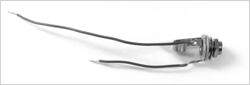
FIGURE 5-6: The wired audio jack
Step 5 If you’re adding the cutoff switch, you’ll do that now. Switches from the hardware store often have screw terminals (as mine does). If your switch has solder lugs, that’s also fine. What matters is that the switch is a normally closed one, meaning it lets electricity through under normal conditions and is momentarily turned off by pressing it. (Many everyday pushbutton switches, like doorbells, are normally open, which means pushing the button momentarily turns the switch on, not off.) Whichever style lugs you have, connect the remaining 3-inch wire to one terminal and the 3-inch wire connected to the jack to the other, as shown in Figure 5-7. It doesn’t matter which wire goes to which terminal.
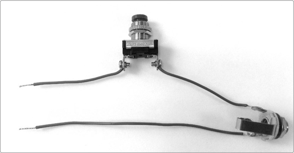
FIGURE 5-7: The wired cutoff switch
Step 6 Set all of your wiring aside and prepare the enclosure. The jack will require a 3/8-inch or 1/2-inch hole. Drill this hole on the short side of the tin. In Figure 5-8, this hole is the one farthest to the left. If you’re using an Altoids tin–style enclosure, place the hole as far from the rolled upper lip as possible, otherwise you won’t have enough clearance for the lid to close once the hardware is inside.
Step 7 Next, drill a 1/4-inch hole in the bottom of the tin, opposite the jack hole. The 1/4-inch hole allows your leads to connect to the play head. As Figure 5-8 shows, this hole is about an inch from the nearest edge of the case and centered. Add a pair of 1/16-inch screw holes near the edge of the tin to secure the play head. Play heads are fairly standard, but just in case, check first to be sure that the screws you retained in Step 2 are slightly larger than 1/16 inch. Also, measure the spacing of the mounting holes; they tend to be around 3/4 inch apart.
Step 8 Finally, add a hole for the switch (if you’re using one—otherwise, skip to the next step). Most large switches, like the one I used here, will fit in a 1/2-inch hole, while smaller “mini pushbuttons” usually need a 1/4-inch hole. Either way, you should drill the switch hole on one of the long sides of the tin, again leaving as much room as possible for the lid to fully close.
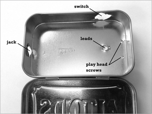
FIGURE 5-8: The distribution of holes in the enclosure, for the jack, the switch, the leads, and the play head screws. (Raggedy holes should work just fine.)
Step 9 Mount the hardware in the tin and string the two loose wires through the 1/4-inch hole in the back of the enclosure, as shown in Figure 5-9.
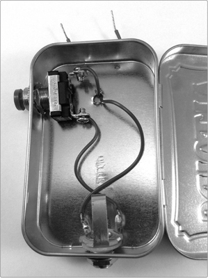
FIGURE 5-9: The hardware in place
Step 10 Time to prepare the play head. Almost all play heads have a set of metal prongs sticking up past their top surface. These functioned as tape guides in the head’s old life playing “Living on a Prayer” and “Power of Love” singles. We don’t need them, so grab them with a pair of needle-nose pliers and bend them back out of the way, as shown on the right in Figure 5-10.
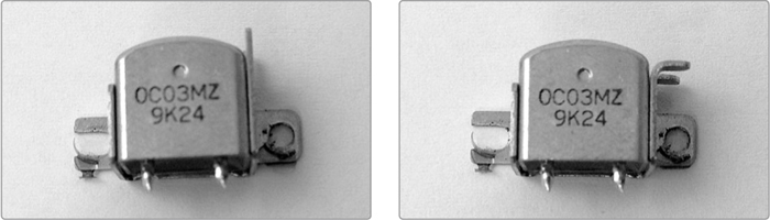
FIGURE 5-10: Before (left) and after (right) shots of the modified play head
Step 11 Next, we need to solder the play head to the wires sticking out of the case. If your play head has only two terminals, then solder one wire to each and be done with it. If it has four, solder one of the two wires to both the terminals on one edge of the tape head (see the left image in Figure 5-11). Repeat this step for the other pair (see the right image in Figure 5-11).
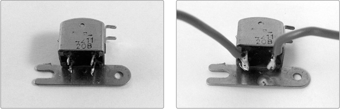
FIGURE 5-11: Wiring the four-terminal play head
Step 12 Finally, mount the play head firmly to the outside of the enclosure using the two screws you salvaged in Step 2, as shown in Figure 5-12.
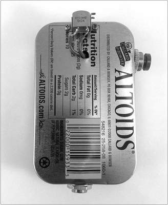
FIGURE 5-12: The back of the finished Scratchbox, showing the mounting of the tape head
Step 13 The completely wired guts of the Scratchbox are shown in Figure 5-13. Now that the wiring is done, plug it into an amp, power the amp up, and rub a credit card magstripe along the play head. You shouldn’t have to search long to find some zips and growls. If you don’t hear anything, then flip to “General Troubleshooting” on page 355 and start checking connections. This is the first full-fledged circuit we’ve built, but it’s still a very simple one. If it’s not working, you probably have a simple short that you can clear up with a little electrical tape and maybe some clipping and resoldering.
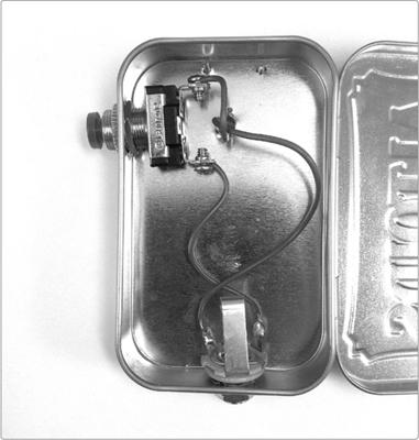
FIGURE 5-13: The guts of your completed Scratchbox. (The play head, which is mounted to the back of the tin, isn’t visible. Flip back to Figure 5-12 to see how that fits onto the case.)
Much like the Plasti-Pickup project, the Scratchbox is best thought of as an exploratory instrument. Start by just rubbing a credit card’s magnetic stripe back and forth along the tape head. You’ll likely get some neat zippy sounds. That’s because there’s a lot of info crammed onto those stripes, and it’s arranged in three very narrow horizontal bands that run along the length of the stripe.
There’s a lot to sift through, so work slowly over short lengths of stripe to really get a feel for the aural possibilities. You’ll get very different dynamics working fast or slow. These are influenced by acceleration, pressure, and how well you track a given band. I find that most credit cards have a good whoop at one end of the stripe or the other, which can become nice sharp chirps if you flick the card aggressively. There’s also often a long, low purr through the middle section of the stripe that you can bring out with a slow, firm push. Try swiping the card in different ways to find the sounds and movements you like.
In terms of musically working a groove, I find it easiest to hold a credit card cupped in my left hand with the stripe facing out and to wield the Scratchbox with my right hand, controlling the cutoff switch with my thumb. (I’m right-handed, so if you’re left-handed, you might try reversing this.) Create rhythms by building up patterns of long and short, or fast and slow, swipes. In turntable lingo, these unarticulated scratches are baby scratches. You can spice these patterns up with a scribble scratch, created by keeping the play head on one especially noisy spot on the stripe and jiggling or vibrating your hand as quickly as possible, allowing only the tiniest movement along the stripe.
The switch we’ve installed is a simple mute. Music is fundamentally about repeating patterns of sound and silence; the mute is handy for dropping in those rests without disengaging from the card’s stripe and risking losing your track. This cutoff switch also allows for the rudimentary emulation of a few classic turntable building blocks created by working the crossfader, a control that brings the volume of one turntable down and the other up simultaneously in a single movement. For example, by cutting a sound off just after it begins, we get a chirp, which is that classic, sharp wsht-wsht-wsht.
Remember that long whoop that usually occupies the middle of the stripe? When you get adept at steadily tracking that sound, you can glide back and forth along it while rhythmically jabbing the cutoff switch, creating an effect known as a transform (so-called because it’s reminiscent of the sound cue that accompanied the Autobots’ and Decepticons’ forward-flip-vehicular-shapeshifting in their 1980s cartoon). The trick to a transform is coordinating the glide and the muting: aim for about four cutoffs per card glide while working back and forth at a steady pace. Musically speaking, the cutoff jabs create little eighth-note bursts against the steady half-note swipes. Search YouTube for turntable chirp, turntable transform, or scribble scratch to familiarize yourself with the aural palette offered by handmodulating, near-random data streams.
If you want even more control, you can replace the mute button with a volume knob—try using a 10k ohm potentiometer with an audio taper (flip to “Resistors: Fixed and Variable” on page 325 if this sounds like technobabble). Connect it by removing the switch and soldering one of the wires to the potentiometer’s center lug and the other to either end lug.
Another good mod is to add a preamplifier. Preamplifiers, often just called preamps, increase signal voltage, while power amplifiers increase the current so that the signal can drive a speaker. In practical terms, preamps tend to bring a low-level signal, like the one coming out of a standard electric guitar, up to line level, which is what something like a mixing board expects. Placing a preamp close to a sensor bumps up the signal-to-noise ratio by amplifying the signal as close to its source as possible, before random electromagnetic waves have much chance to seep into the chain. The result is a fuller, more aggressive sound with more details for you to pick out and explore. Try using the Scratchbox with the Mud-n-Sizzle Preamp (Project 12). Crank the volume up, and push the tone to the “sizzle” end of the spectrum. The “Two-Transistor Fuzztone” on page 364 is also an effective preamp for most Scratchboxes. Or you can build a basic 9-volt powered preamp into your Scratchbox; the “Basic Transistor-Based Preamp” on page 364 is a perfect fit.