You can individually trigger notes with the red button—much as you individually trigger notes by plucking a guitar string or striking a piano key.
The Single-Chip Space Invader Synth sounds a lot like the old-school console and arcade games that inspired its name because it relies on many of the same soundgeneration techniques. Early video games couldn’t play prerecorded sounds—not even brief, low-resolution samples. All of their sound effects had to be created by mixing tones generated by simple circuits like those found in this project. Did the results sound realistic? No! Every explosion is a simple burst of static, and the entire Space Invaders soundtrack is just four notes steadily looping at an ever-increasing tempo. These sounds are primitive, but like many primitive expressions, they’re also primal. The games themselves have faded—when was the last time you paid 25 cents to bull’s-eye regularly descending alien crafts?—but artificially lo-fi chiptune music is thriving. And you can craft yourself a shiny fistful of that primal electronica.
The Single-Chip Space Invader Synth has two nonidentical sound-generating circuits, or oscillators. (In this case, they’re square-wave oscillators, which means that the oscillators generate square-shaped waves, rather than triangles, sawtooths, or smoothly curved sine waves.) One oscillator is responsible for producing the pitch of each tone, while the other is used to modulate that primary pitch. The two square-wave oscillators are diode mixed, resulting in a very basic kind of FM synthesis that readily lends itself to old-school chiptune effects, like revving lightbikes and laser blasts.
The Single-Chip Space Invader Synth has two playing modes:
You can individually trigger notes with the red button—much as you individually trigger notes by plucking a guitar string or striking a piano key.
You can also flip the hold switch to continuously produce sound while you run the knobs, making the synth a bit like a theremin1 with a much richer tonal palette and much less frustrating controls.
As an added bonus, this 9-volt brute is capable of driving a set of headphones or its own little speaker, so you can easily switch from rocking out loud-and-proud to practicing in private without ever getting off the sofa.
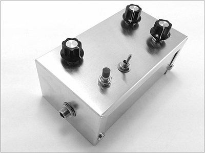
FIGURE 15-1: The finished Single-Chip Space Invader Synth
The Single-Chip Space Invader Synth purposefully relies on cheap commodity parts used in slightly unconventional ways. The result is that every Single-Chip Space Invader Synth is unique, with its voice and control response influenced by the idiosyncrasies of your components, case, hardware, lengths of wire, and much more.
Hear the Single-Chip Space Invader Synth in action in the samples at http://www.nostarch.com/jamband/.
Build Time
About 1 hour
Tools
A standard soldering kit (See page 340.)
A ruler that shows 1/4-inch increments or smaller
An electric drill with bits (You’ll probably need 3/16-inch, 5/16-inch, and 3/8-inch bits.)
An amp and instrument cable for testing the synth
(Optional) Other tools to work your enclosure (If you’re using a wooden enclosure, you’ll want sandpaper and possibly files to clean up drill holes.)
(Optional) Foam-backed double-sided tape or hardware to mount the circuit in its enclosure
(Optional) A hacksaw for trimming down potentiometers with long shafts
Supplies
A CD4093 integrated circuit, such as Digi-Key part #296-2068-5-ND
A 14-pin IC socket
A red LED
Two 1N4148 silicon diodes (Mouser part #78-1N4148 is shown in Figure 15-2, although any generic 1N4148 or 1N4150 is fine.)
Two 0.1 μF capacitors (marked 104)
A 220 ohm resistor (red-red-brown stripes)
A 470 ohm resistor (yellow-violet-brown stripes)
A 10k ohm audio potentiometer (This is a variable resistor with an audio taper; see “The Gory Details: Audio Taper vs. Linear Taper” on page 327.)
A 100k ohm potentiometer (A linear taper is best; if the potentiometer isn’t otherwise labeled, you can assume it has a linear taper.)
A 500k ohm potentiometer with a linear taper
Three control knobs that fit your potentiometers
Two small SPST toggle switches (You can use Mouser part #108-MS550K, for example, but any similar switch will work.)
An SPST pushbutton switch, such as Mouser part #103-1012-EVX or a nonilluminated doorbell button
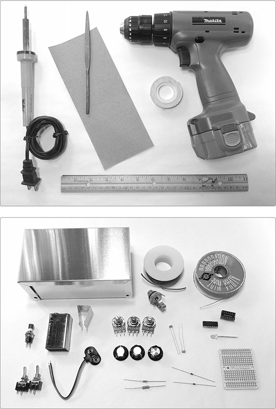
FIGURE 15-2: Tools and supplies (not shown: hacksaw, instrument cable, and amp)
A 9-volt battery clip
24-gauge insulated hook-up wire (Stranded wire is best.)
22- or 24-gauge bare bus wire (This is uninsulated solid core wire.)
A 1/4-inch mono phone jack, also called a guitar jack
An Adafruit Perma-Proto Quarter-sized Breadboard PCB (Adafruit product #589 or Maker Shed product #MKAD48)2
A sturdy enclosure (Cigar boxes are fun—folks are delighted by the inherent contrast of the synth-in-a-cigar-box—while a simple all-metal enclosure lends an apt sort of space-age retrofuturism. See “On Enclosures” on page 214 for more options.)
(Optional) A 9-volt battery holder clip, such as Digi-Key part #71K-ND or Mouser part #534-071
As with other electronics projects, we’ll begin with the hardware to allow you to freshen up your soldering skills on the least delicate components. Then, we’ll move on to building the circuit itself before connecting it all and installing the functioning project in an enclosure.
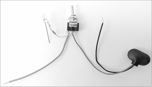
Step 1 Start with the power supply and indicator LED. Take out the 9-volt battery clip, one of your SPST switches, the 470 ohm resistor (yellow-violet-brown stripes), and the LED. Strip and tin the positive (red) lead on the battery clip and then solder it to either of the two lugs on the switch. (If you’re new to soldering, flip to “Soldering” on page 346 now for instructions.) Next, solder the 470 ohm resistor to the positive leg of the LED; the positive leg is longer, while the negative is closer to the flat section of the LED lens. Finally, cut, strip, and tin a 4-inch length of wire. Twist together one end of the wire and the free leg of the 470 ohm resistor, and solder this twisted pair to the empty lug of the switch. Figure 15-3 shows the results.
FIGURE 15-3: The prepared power switch and supply with indicator LED
Step 2 Next up are the three potentiometers, or pots. Start by preparing their leads: cut six 4-inch lengths of insulated wire, strip them, and tin the ends. The 10k ohm pot and 500 ohm pot are wired identically. In each case, one wire is soldered to lug 2 and one wire to lug 3. Remember that lugs are numbered from left to right when viewed from the front, with the pot shaft pointing toward you and the lugs on top. In Figure 15-4, the 10k ohm and 500k ohm pots are the left and right pots, respectively. For the 100k ohm pot, solder one wire to lug 1 and one wire to lug 2, as shown in Figure 15-4, where the 100k ohm pot is in the middle of the lineup. Set the 100k ohm and 500k ohm pots aside and keep the 10k ohm pot handy for Step 4.
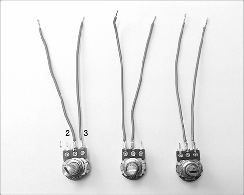
FIGURE 15-4: The prepared pots, from left to right: 10k ohm, 100k ohm, 500k ohm
Step 3 Now we’ll start working on the output controls, which offer two options for playing notes: a pushbutton trigger for playing individual notes and a toggle hold switch that you can flip for continuous output. Cut four 4-inch insulated wires, and strip and tin the ends. Dig out your remaining SPST toggle switch and your single SPST pushbutton switch; solder one wire to each lug on each switch (see Figure 15-5).
Step 4 Next, we’ll connect the trigger and hold switches, 10k ohm volume pot, and output jack. First, take the 10k ohm pot and solder the wire from lug 2 to the tip lug of your 1/4-inch output jack. This is the lug that connects to the jack’s metal tongue. (If you need a more detailed diagram of instrument jack and plug anatomy, flip to “Quarter-Inch Phone Plugs and Jacks” on page 337.) Take the two switches, twist together the ends of one wire from each switch, and solder this pair to lug 1 of the 10k ohm pot, as shown in Figure 15-6. Set aside the hardware until Step 12.
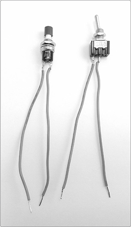
FIGURE 15-5: The prepared trigger (left) and hold (right) switches
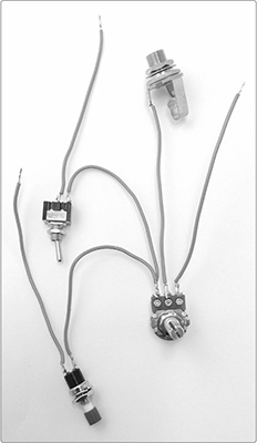
FIGURE 15-6: The finished output assembly
Now that the hardware is done, it’s time to take a look at the circuit diagram, shown in Figure 15-7.
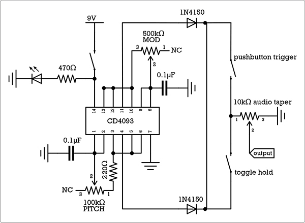
FIGURE 15-7: The circuit diagram for the Single-Chip Space Invader Synth
One neat thing about this circuit is that we get both oscillators from a single IC. In fact, the chip could provide as many as four oscillators: it has four identical logic sections, and each can serve as a usable oscillator by itself. We’ll use two logic sections per oscillator3 and mix those outputs using the diodes you see along the top and bottom of the circuit diagram.
Most of the time, audio signals are mixed using resistors. For example, that’s what you’re doing when you use a soundboard to mix the signals from several instruments and mics so that they can all come out of one set of speakers. On the Twang & Roar Kalimba (Project 11), we wired up a single pot to work as a simple mixer so that we could blend the signals from two different kinds of pickups. Resistor mixing generally only allows you to add signals together. If the resistors are variable, you can also control the ratio of each signal.
But diode mixing of two very similar signals—like the pair of square waves being produced by the CD4093 in this configuration—is different. It allows the signals to either add or subtract from each other, creating complex new waveforms. Each oscillator by itself can produce only a string of evenly spaced, identical square waves. But if you hook the Space Invader Synth’s final diode-mixed output to an oscilloscope and watch the readout while adjusting the synth’s pitch and mod controls, you’ll see regular square waves, irregular square waves, regular groupings of square waves, or even more complex shapes, like repeating patterns of stairsteps or ziggurats.
If this is your first IC project, please take a moment to flip back to Step 1 of the Droid Voicebox on page 76 to familiarize yourself with the layout and orientation of an IC (which often confuses newcomers). You’ll note that we’re using an IC socket in this project. Lots of folks just solder their ICs directly to the circuit board. Please don’t do this. The IC is sensitive to both heat and static electricity. Soldering to an empty socket and then inserting the IC in the end will avoid headaches and save you a lot of time if the IC fails later. Swapping out a socketed IC takes a few seconds; desoldering 14 IC pins is fiddly business that takes longer than rebuilding the circuit from scratch.
The AdaFruit PCB listed in the supplies has its columns and rows conveniently numbered and lettered. I’ll use these coordinates to indicate where components should be placed. If you’ve used another brand of breadboard-style circuit board, just follow along with the illustrations.
Step 5 Place the IC socket so that it straddles the horizontal divide along the middle of the PCB, with one end of the socket at holes 3F and 3E and the other at 9F and 9E (see Figure 15-8). Flip the PCB over and solder socket pins 1, 2, 4, 5, 6, 7, 8, 9, 10, 11, 12, 13—that is, every pin other than pins 3 and 14—to their respective pads. IC pins are numbered counterclockwise from the lower left, as shown in Figure 15-8.
Step 6 Place your nine jumpers. Cut eight 3/4-inch lengths of bare bus wire. Bend four of these into skinny Vs and mount them from pad 3D to pad 4D, 7A to 8A, 8G to 9G, and 4G to 5G. Solder these now. Next, bend four lengths of bus wire into flat-bottomed Us and mount them from 5C to 7C, 5H to 7H, 11F to 11E, and 9A directly to the lower ground rail. (The ground rails are the rows of holes at the top and bottom of the PCB, directly below the blue lines marked with minus signs.) Solder these jumpers, being mindful not to push the jumpers down flush with the surface of the PCB, where they might cause short circuits with holes they’re supposed to be jumping over. Figure 15-9 shows all these connections.
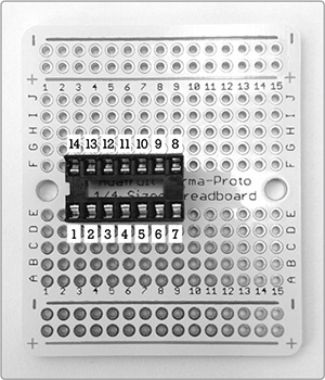
FIGURE 15-8: Positioning the IC socket. Sockets are symmetrical, but if yours has a notch at one end, as mine does, it’s traditional to place that to the left so that it aligns with the orientation markings on the IC.
Step 7 For the final jumper, cut a 2 1/4-inch length of bare bus wire and run it along column 14, from the top ground rail to the bottom ground rail, as shown in Figure 15-9.
Step 8 Add the two 0.1 μF capacitors, or caps. Run one cap from 4A to the lower ground rail and the other from 9J to the upper ground rail (see Figure 15-10). It doesn’t matter which leg goes in which hole as these caps are nonpolarized. Solder the caps now.
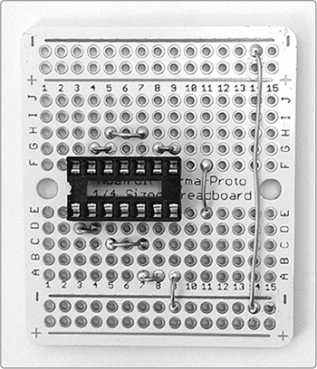
FIGURE 15-9: All the jumpers are in place.
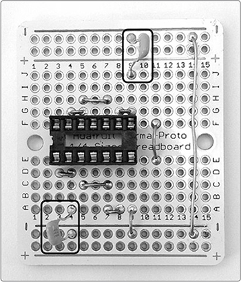
FIGURE 15-10: Mounting the 0.1 μF capacitors
Step 9 Connect the diodes. Unlike the caps, the diodes are polarized, so each has a positive and negative leg. The negative leg is indicated by a dark stripe on the body of the diode. For both diodes, that stripe will go to the right, as shown in Figure 15-11. Run one diode from 6I to 11I and the other from 6B to 11B. As with other components spanning multiple columns, be mindful not to press the legs down flush with the surface of the PCB because this could create short circuits in the intervening columns. Solder the diodes now.
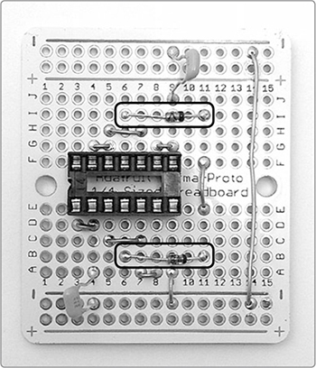
Step 10 Add the 220 ohm resistor (red-red-brown stripes). Run this resistor from 5D to 10D. Solder both ends of the resistor as well as IC socket pin 3, as shown in Figure 15-12.
FIGURE 15-11: Adding the diodes. Note that in both cases, the negativeleg stripe is to the right.
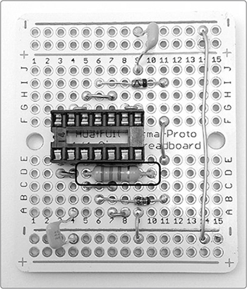
FIGURE 15-12: The 220 ohm resistor
Remember all that hardware from the first few steps? It’s time to connect it to the PCB. In this section, we’ll install the pitch control pot, the modulation pot, the trigger button, the hold switch, and the power.
Step 11 First, install the pitch control, which is the 100k ohm pot. Run the lug 2 lead to solder pad 3A and the lug 1 lead to 10A. Solder these leads now. Next, install the modulation control, which is the 500k ohm pot. Run the lug 2 lead to 9H and the lug 3 lead to 7J. Solder these now. Figure 15-13 shows the results.
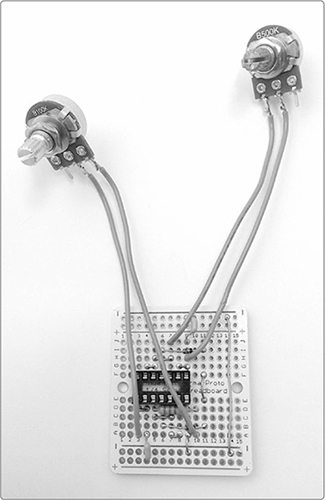
FIGURE 15-13: The pitch-control and mod-control pots are installed.
Step 12 Grab the output assembly you completed in Step 4 on page 271. Run the remaining lead on the toggle switch to 11D and the lead on the pushbutton switch to 11G. Solder both now. Then, take the lug 3 lead on the 10k ohm pot, which is the volume control, and connect it to the rightmost hole on the PCB’s lower ground rail (see Figure 15-14).
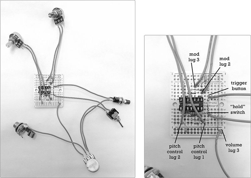
FIGURE 15-14: The circuit with completed output (left) and a labeled detail of the PCB (right)
Step 13 Now to add power! Run the negative (black) battery wire to the lower ground rail, connecting it to the rightmost empty hole, as shown in Figure 15-15. Then, run the insulated wire connected to the power switch—that is, the positive power supply—to pad 3G, which will connect it to pin 14 of the IC. Solder both connections now.
Step 14 Finally, add the last two ground connections. Cut a pair of 4-inch insulated wires and strip and tin both ends of each. Solder one wire to the open leg of the LED, which is the one that’s aligned with the flat-edged LED lens and which was originally the shorter leg. Run the other end of this lead to the rightmost empty hole in the lower ground rail, next to the negative power lead you just installed. Connect the remaining 4-inch lead to the unwired lug on the output jack. (This is the ground lug that connects to the metal sleeve inside the jack.) Run the other end of this lead to the rightmost hole of the PCB’s upper ground rail, in the top right corner of the PCB. These ground connections are illustrated with black wires in the labeled diagram in Figure 15-15. Solder both ground wires to the PCB.
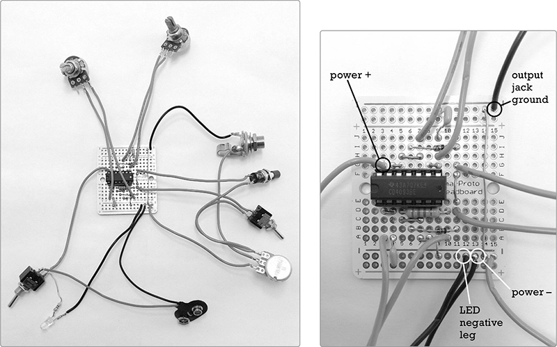
FIGURE 15-15: The finished guts of the Single-Chip Space Invader Synth (left) and a labeled close-up of the new ground connections added in Step 14 (right). Note that the IC is now mounted in its socket.
Step 15 Now, press the IC into its socket—the notch goes to the left, just like the notch on the socket—and you’re ready to fire her up!
Time for troubleshooting! Connect a fresh 9-volt battery; if the LED doesn’t light up, flip the power switch. If you still don’t get a response from the LED, look for short circuits; stray snips of wire or little scraps of solder touching adjacent pads, traces, or lugs are often the culprit. Check the jumper connections, too, to make sure the wires bridging several columns are not brushing against unintended solder pads.
If you find any short circuits, eliminate them. Loose scraps of wire or flakes of solder can usually be blown or flicked away, while most sloppy solder joints can be smoothed out by reheating them. The solder naturally flows to the warmer joint. If a solder bridge is especially stubborn or there’s just too much solder gunked onto a joint, you may need to desolder (see “Desoldering” on page 349) and redo the connection.
Once your synth powers up, turn the 10k ohm volume pot fully counterclockwise, hook the synth to your amp, set the amp volume to its midpoint, and flip it on. Depending on the position of your toggle hold switch and the sensitivity of your amp, you may already hear the synth buzzing. If you don’t hear anything, hold down the pushbutton trigger and turn up the volume on the synth itself. If you get to full volume and still hear nothing, turn the volume back down, flip the hold switch, and repeat. If you now have sound, then there was something wrong with your pushbutton switch. Look for shorts on its terminals, and if everything appears fine, replace the pushbutton. Still no sound, regardless of the hold switch’s position? Look for more short circuits. The hardware—especially the output jack itself—is frequently the guilty party at this stage.
Once you have sound, test the two output switches. The pushbutton trigger should give short bursts of sound that last as long as you hold the button, while the toggle hold switch should give a continuous sound. If the toggle is off and you aren’t pressing the pushbutton, then you should hear nothing. The toggle overrides the pushbutton, so if the toggle is on, the pushbutton should have no effect.
Next, flip the toggle so you have a continuous tone. Turn the 500k ohm pot—the modulation controller—fully counterclockwise, and then twist the 100k ohm pot—the pitch controller—back and forth. The pitch of the tone should clearly go higher as you turn clockwise and lower as you turn counterclockwise. Set the pitch controller to the middle of its range and turn the mod pot back and forth. The timbre should vary wildly as you do so: at the extreme clockwise position, it should take on a rhythmic beating, revving up as you turn the knob counterclockwise, until it reaches zip-zappy extremes.
If either pot behaves in the opposite way to what I’ve described, it just means that you used lugs 1 and 2 instead of lugs 3 and 2 (or vice versa) when building the controller. This common mistake is really no biggie. You can swap the leads on the pots to match my build or leave them as they are and operate “goofy foot.” It’s totally a matter of personal preference and aesthetics.
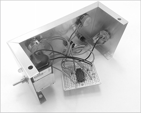
Once you have the synth working, box it up. I’ve chosen an aluminum project box enclosure (as shown in Figure 15-1 and Figure 15-16) because it shields against interference and looks suitably “space age.” (I’ve also already used plenty of cigar boxes in this book.) There are many ways to play the Space Invader Synth, so consider several packaging options and see which you like best. You might decide that the tastiest sounds are easier to achieve with the synth sitting on a tabletop. In this case, use a heavier case that won’t get pulled off the table when someone brushes against your instrument cables. If, however, you have more fun holding the synth and tweaking knobs like a mad hatter, then you’ll probably want to use a lightweight, easy-to-hold box.
FIGURE 15-16: The Single-Chip Space Invader Synth mounted in its aluminum case
With any enclosure, remember the following:
Choose a box you can machine with the tools you have. That is, if you only own a rechargeable hand drill, don’t try to package your synth in an old steel ammo case.
Secure the batteries to the box with clips and the PCB with screws or double-sided tape if you think they’ll otherwise rattle around.
If you have a metal enclosure, either insulate the PCB, bare wires, and solder points, or line the inside of the case with something nonconductive, like electrical tape, duct tape, or contact paper.
* NOTE: For more detailed instructions on insulating or shielding your enclosure, see the Twin-T Phaser/Wah’s “Tips, Tricks, and Mods” on page 262.
When drilling holes for your hardware, you’ll probably want a 3/8-inch drill bit for the output jack, a 5/16-inch bit for the pushbutton switches and pots, a 1/4-inch bit for the toggle switches, and a 3/16-inch bit for the LEDs. Your components may have slightly different dimensions, however, so make sure to double-check before you drill.
I’m going to come clean: this instrument is purposefully obtuse. The point of the Space Invader Synth is to make it easier to create your own jams than it is to once again plunk out “Twinkle, Twinkle, Little Star.” Yes, someone with a decent ear can definitely pick out tunes on this synth, but even total newbies will immediately construct their own riffs, rhythms, and yowling solos.
An easy way to start is to flip the hold switch off, dial in a volume and modulation you like, and then restrict yourself to working only the pushbutton trigger and pitch control. Aim to produce a repeating pattern of three or four steady pitches, with the occasional slide or slur (achieved by holding down the trigger button while you twist the pitch control knob). If you can operate a combination padlock, then you can work that pitch knob with enough precision to hit the same notes repeatedly and lay down a zappy little groove.
If you want something more cosmic and synthy, play in theremin mode: flip the toggle hold switch and then control the pitch with one hand and the volume with the other. This allows you to glide smoothly from note to note,4 articulating and differentiating individual notes by cutting the volume. If you carefully work the volume knob as you move from pitch to pitch, you can get that wavering, swooping operatic sound emblematic of the theremin—think of the original Star Trek television series theme5 or the swooping synth licks in the chorus of The Beach Boys’ “Good Vibrations.” This last example was played on the Electro-Theremin,6 a simple singleoscillator sine-wave synth that is operationally very similar to our Space Invader Synth.
Try tweaking the pitch and modulation knobs simultaneously, turning them either in the same or alternate directions at various rates. Do this in both theremin and trigger operating modes. You’ll quickly discover a rich world of old-school video game sounds, including zip-zap space blasters, racing lightbikes, speeding saucers, and deeply disgruntled androids.
One quick tip as you explore: a simple volume pot, like the one we’ve used here, doesn’t attenuate all frequencies evenly. This is something you can address with a little soldering (check out “Extra-Presence Volume Control” on page 366), but I like it as is. Because we’re mixing two independent square waves, this uneven attenuation is especially noticeable, uncovering stark new timbres, textures, and aural delights as you alter the volume, even if you leave the pitch and mod controls untouched.
If you want a more conventional playing experience, check out the resistor ladder mod described in “Add a Keyboard” on page 284.
Despite the low part count, there’s a lot going on in this little Single-Chip Space Invader Synth—which means lots of opportunities to mod!
This synth produces a nice, strong line-level output, which is sufficient to drive headphones or a small speaker, albeit somewhat quietly in many cases. Have an old set of “cans” (i.e., big ole headphones that cover the entire ear) with a 1/4-inch jack? Plug ’em in! You can also connect any pair of headphones you own using a 1/4-inch-to-1/8-inch adapter plug. (Such an adapter looks like a 1/4-inch plug with a built-in modern headphone jack; you can find one at most electronics shops or in the audio/video section of any big-box store.) Now you can jam without annoying everyone you live with.
* NOTE: Do you hear your synth through only one side of your headphones? That’s totally normal, as headphones are built for stereo sound and your synth is strictly mono.
As for adding external speakers, both new and secondhand speakers in the 3 ohm to 8 ohm range should work when wired directly to the output. In general, a speaker with a larger diameter will give you better bass response, and a lowerresistance speaker will be louder.
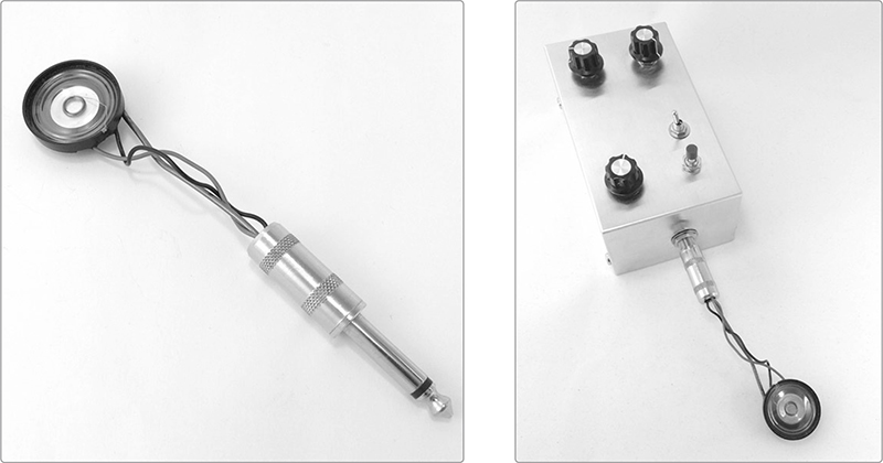
If you have a large enclosure, you could include a built-in speaker. This could replace or complement the output jack; flip back to Project 7 and check out “Modify the Output” on page 100 for ideas. Alternatively, you can easily build an add-on monitor speaker. Just solder your speaker’s two leads to the tip (positive) and sleeve (ground) connections on a standard 1/4-inch plug. For example, the little dandelion speaker shown in Figure 15-17 is a 1-inch diameter 8 ohm speaker with its leads soldered to an old guitar-cable plug. Secure a piece of coat hanger inside the plug, glue it to the back of the speaker’s magnet, and you have a sturdy little add-on accessory. You can see it mounted on the Space Invader Synth in Figure 15-17 (right).
FIGURE 15-17: A simple dandelion speaker for your Single-Chip Space Invader Synth
The Single-Chip Space Invader Synth plays well with many commercial and homebrew effects. On the commercial end, try pumping your Space Invader Synth through a digital delay pedal,7 chorus pedals, phasers, and some distortions. You can buy super dinged-up—but perfectly functional—stomp boxes at secondhand guitar shops and pawn shops, where they often go cheap. If you live in a college town, as I do, Craigslist can also be a fairly reliable source for some fantastic deals.
As for homebrew effects, the Space Invader Synth works well with the low-pass filter built in the Mud-n-Sizzle Preamp (Project 12), the Blinkie Tremolo (full build instructions are in my first book, Snip, Burn, Solder, Shred), and the Universal LFO (Project 13). The tremolo effect works best if you keep the synth’s output volume fairly low, but you can boost it back up by placing the Mud-n-Sizzle Preamp after the trem unit.
The Space Invader Synth can get along well with the Twin-T Phaser/Wah (Project 14) if you use the “ground connection break” trick described in its “Tips, Tricks, and Mods” on page 262. Unfortunately, completely breaking the ground connection tends to kill most of the low-end from the Space Invader Synth’s output. Inserting a 1M ohm resistor in the ground connection between the two circuits, instead of breaking the ground completely, results in a decently balanced output signal that’s still responsive to the twin-T filter.
The CD 4093–based oscillator in the Single-Chip Space Invader Synth can be savagely loud, capable of overdriving basically any amplifier. The way we’ve wired the LED indicator lamp significantly tames that tone for an old-school videogamey bleep-bloop vibe. For a much more aggressive sound, simply omit the indicator LED and its resistor. For a sound that’s roaringly aggressive while still fairly manageable, remove the LED/resistor pair from the power line and instead connect the LED’s positive leg to pin 11 of the IC and its negative leg to the ground (leaving out the resistor). In this configuration, the LED will dirty up your tone some and also blink at the rate of the modulation oscillator.
To smooth out the synth’s reedy buzz-jangle, you can add a simple adjustable low-pass filter, such as the one in “Low-Pass Filter” on page 365. (This is fundamentally the same filter as the one we built into the Mud-n-Sizzle Preamp.) Once you build the filter, it’s really easy to install: just connect lug 1 of the filter’s control pot to the output lug on the synth’s jack (so that both the filter and the PCB are wired to the jack). You can solder the filter’s ground connection to any point on the PCB’s ground rail.
The 220 ohm resistor mounted on the PCB sets the highest pitch the oscillator can generate. Wanna be able to hit higher notes? Decrease the value of this resistor. Wanna be able to hit lower notes? Increase the value of this resistor. Just keep in mind that changing this resistor shifts the oscillator’s range; it doesn’t expand it. If you swap in a lower-value resistor, you’ll be able to hit higher notes at the expense of losing some of the low notes, and vice versa. This particular oscillator can produce tons of sounds that are too high to be heard by human ears or too low frequency to be perceived as continuous tones. If you want to mostly keep your synth’s voice in the audible tone range, stick with a resistor around 200–300 ohm.
If you want to increase the range of the pitch controller, use a larger variable resistor than the 100k ohm pot I’ve specified. Because the highest note the oscillator can play corresponds to zero ohm (a resistance any standard pot can be set to), increasing the value of this pot effectively adds more low-frequency pitches to your controller.
If you’re thinking about swapping in a higher-value pot, there are a couple things to keep in mind. First, expanding the range means cramming more notes onto the same size dial. Yes, you have more notes to choose from, but zeroing in on any specific note while playing becomes increasingly difficult. If you make it hard to repeatedly hit the same note, then it’s going to be hard to play a recognizable riff. Second, because the synth outputs square waves, your pitch can go only so low before the continuous tone falls apart and becomes a series of discrete beats, which are the flat-topped peaks of those square waves. This starts to happen with pots around 500k ohm.
The 100k ohm pitch pot is a good compromise between range and conventional playability. With the 100k ohm pitch pot, you end up with about two octaves centered on middle C—which is fairly useful in traditional music, while still offering an enjoyably broad sonic landscape. It’s still fairly plausible that an average musician or dedicated newbie will be able to coax out a passable version of “When the Saints Go Marching In” from such a synth, if that’s what floats their boat.
* NOTE: You can make the same changes—adding a resistor in series with the pot or swapping pot values—to the modulation pot and thereby alter its range or cap its maximum frequency.
Finally, the 0.1 μF caps set the lowest pitch each oscillator can hit; the higher the capacitance, the lower the lowest pitch you can play. But again, bear in mind that you can go only so low before your tones become thumps. If you choose to go with the higher-value polarized electrolytic caps, be sure to connect the positive leg to the chip and the negative leg—the one aligned with the stripe on the cap body—to the ground.
There are several circuit mods you can try that change how you play the synth and open up further sonic possibilities. Here are three examples:
Add a pushbutton mute—like the one in the Scratchbox (Project 5)—to the modulation oscillator. Muting the modulation oscillator allows you to immediately convert your complex, multitone timbre to a pure square-wave tone. To add such a mute, add a normally closed pushbutton switch—abbreviated NC8—just before the diode in the upper half of the circuit diagram in Figure 15-7. (This will involve desoldering the diode’s positive lead from pad I6 and inserting the switch between the diode and PCB).
Build in a Universal LFO (Project 13) to augment the modulation control, the volume control, or even the pitch control itself. See “Using the Universal LFO” on page 234 for guidance.
Replace the 100k ohm pitch control pot with either a photoresistor or a set of body contacts, like the ones used in the Droid Voicebox (Project 6). This drastically changes the way you interact with pitch control and is great for sound sculptures. Both of these mods also dramatically increase the sonic range of your synth, injecting a good deal of randomness into performance and play.
Each pitch your Single-Chip Space Invader Synth produces corresponds to a specific resistance dialed in on the pitch-controller pot. For example, on my prototype synth, middle C is 52k ohm, C♯ is 49k ohm, D is 46k ohm, D one octave higher is 19k ohm, and so on.
* NOTE: If all these Ds and Cs are throwing you off, flip to Appendix C for a crash course in music theory.
It stands to reason that you should be able to remove the 100k ohm pitch pot from your Space Invader Synth and replace it with a set of resistors—each corresponding to a specific note—wired to a set of pushbutton switches (as illustrated in Figure 15-18).
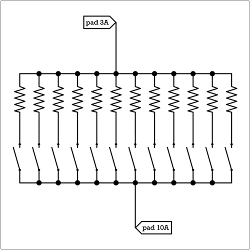
FIGURE 15-18: An abstract (and impractical) circuit diagram for a resistance-based synth keyboard
Theoretically, each switch should behave much like a piano key. For example, when you activate the middle switch, that single resistor—let’s say it’s a 52k ohm resistor—will connect pad 10A to pad 3A, and thus the synth would play middle C.
But there are several problems with this scheme. First and foremost, 52k ohm resistors are as rare as hen’s teeth. Resistors are generally available only in certain common values, and few of your notes will map exactly to those values. In two octaves—24 notes, in this case, centered on middle C—I found that only about one-fourth of the notes my synth played corresponded to commercially available resistors.
But even if resistors were made in every conceivable value, I still couldn’t just give a chart of resistances and the notes they produce, as I did for the tine lengths and notes of the Twang & Roar Kalimba (Figure 11-21 on page 190). This is because my list of resistances probably wouldn’t work for you. Individual component tolerances, the lengths of your wires, the quality of your supplies and soldering, the charge on your 9-volt battery, the temperature of the circuit, local weather, and other similar seemingly trivial factors all stack up to impact the pitch your synth plays. Any list of values that work for my synth likely won’t sound great on yours.
That said, there are still lots of ways to build a keyboard for a synth such as this one—it’s just that many of these approaches are either pricey or maddeningly futzy. If you’re feeling ambitious, I’ve included the least insane keyboard scheme in Figure 15-19, which shows the guts of a simple one-octave string resistor ladder keyboard prototype I whipped up for my Space Invader Synth.
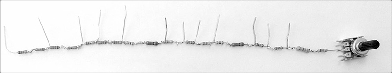
FIGURE 15-19: A single-octave string resistor ladder for my Single-Chip Space Invader Synth
This simple network of resistors makes it possible to hardwire a series of very specific resistor values and, thus, to (fairly) reliably play a fixed set of notes, such as two full chromatic scales (explained in Appendix C), which is pretty darn handy if you have a thing for popular Western music produced in the last several centuries. String resistor ladders like these are exceedingly cheap and easy to build, which is why cheap toy keyboards generally rely on them. They’re also very flexible, allowing for a variety of interface choices for your keyboard.
To begin experimenting with a two-octave string resistor ladder keyboard for your Single-Chip Space Invader Synth, gather an 18k ohm resistor (brown-gray-orange stripes), a small 10k ohm linear resistor (even a trim pot will do), a fistful of 1k ohm resistors, a few 2k ohm and 3k ohm resistors, a chromatic tuner, and your soldering tools.
Step 1 Begin with your 18k ohm resistor (brown-gray-orange stripes) and solder a string of about 30 1k ohm resistors to it. As you finish each solder joint, don’t trim the excess lead from both resistors. Instead, bend out one leg at each junction, as shown in Figure 15-19. These “rungs” will become important later.
* NOTE: This might sound like a lot of soldering, but you can easily do this entire process—from soldering the initial ladder to finding notes, adding any needed resistors, and finishing off the ladder—in under an hour.
Step 2 Tape this resistor ladder to a piece of cardboard; this will keep it steady and give you a place to keep track of the results as you search for notes. Position the ladder with the 18k ohm resistor to the right.
Step 3 Turn the pitch control pot on your synth fully counterclockwise, connect the 18k ohm end of this string of resistors to lug 2 of your control pot, and connect a stripped and tinned length of insulated wire to lug 1. Henceforward, we’ll call this insulated wire your stylus.
Step 4 Power up your amp and synth, and then touch the end of your stylus to the rung at the junction between the 18k ohm resistor and the first 1k ohm resistor. You should hear a high pitch. Check your chromatic tuner; it’ll likely tell you that this is a fairly out-of-tune D5 or E5, but it could be a higher note. If it’s a recognized, in-tune note, write the note down on the cardboard above that junction. Then, check the next junction. Work your way up the ladder in this fashion, one rung at a time, checking each and noting where the in-tune notes are. You’ll probably find usable notes at every few junctions; they’ll tend to space out as you move up the ladder.
Step 5 If you don’t find all the notes you need, add more resistors to the end of your ladder. Try 2k ohm and 3k ohm now because you’ll be in the lower registers. Test each of these new junctions, jotting down where your in-tune notes are. Try to find about 24 consecutive notes for a highly playable keyboard.
Step 6 Once you’ve found your notes, go back to each junction where there’s no useable note and trim away the rung as I’ve done in Figure 15-19. Now each of your remaining rungs should correspond to a recognized note in the chromatic scale.
Step 7 Finish your string ladder keyboard by adding a small linear pot, such as a 10k ohm, as shown in Figure 15-19. The overall pitch of your keyboard will inevitably drift with the weather, battery power, component age, jostling, and so on. This pot will allow you to retune the keyboard as a whole or to do cool detuning warbly effects as you play. At this point, you can wire pushbutton switches to each rung (see Figure 15-20).
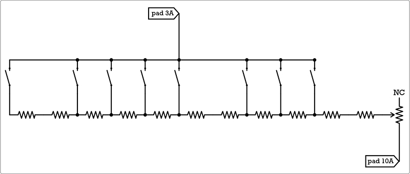
FIGURE 15-20: An abstract circuit diagram of an abridged string resistor ladder keyboard
These buttons work like piano keys, with your highest note at the far right and your lowest at the far left. Personally, I prefer to forgo the buttons and just keep using the stylus to play the ladder.
One neat way to package the ladder is to mount a series of metal screws in the top of a wooden or plastic enclosure, laying them out like piano keys, and to connect each of these virtual piano keys to its corresponding rung inside the case. Then, you can tap each screw head with your stylus to play the desired note. This description might seem clumsy, but that’s exactly how commercial Stylophones, like the one shown in Figure 15-21, work. Be the envy of your block with your very own completely custom DIYlophone!
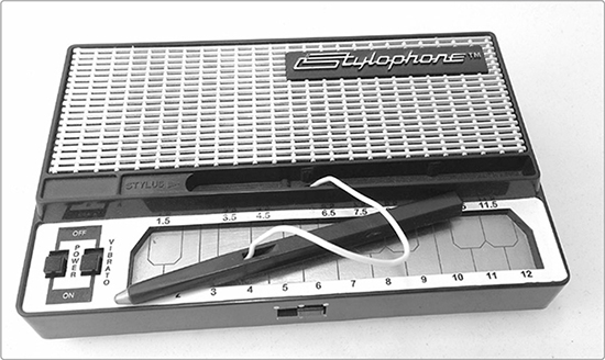
FIGURE 15-21: A commercial Stylophone uses a resistor ladder and stylus for the keyboard control.
If you’ve dug building this synth, then you should get your hands on a copy of Nicolas Collins’s book, Handmade Electronic Music: The Art of Hardware Hacking (Routledge, 2006). It includes tons of great, open-ended projects for building simple synths like this.
I also recommend you look up Tim Escobedo’s Synthstick from his legendary, sadly defunct, FolkUrban DIY musical instrument site, archived here: http://www.oocities.org/tpe123/folkurban/. That build taught me to hack a single oscillator from a CD 4093 Quad NAND Schmitt Trigger IC, and I’ve never regretted it for a moment. If you’re interested in Tim’s other electronica hijinks, you can find archived PDFs in the “Resources” section of my site: http://www.davideriknelson.com/sbsb/resources/.