Human perception and learning is 90% visual. And yet people are more critical of what they hear than what they see. Because audio comprises a much smaller percentage of human information gathering, even a small audio discrepancy will translate into a much greater perceptible difference. It has been found through experimentation and research that people will watch poor-quality film and video as long as the audio is good. On the other hand, an audience will not tolerate poor audio, no matter how good the video is, because it is more of a strain to make sense of the content. If audio is out of sync by one or two frames, it is obvious and annoying. Even so, audio is often thought of as less important than video. But this is simply not the case.
Measuring Volume as Decibels
The human ear responds to a remarkable range of sound amplitude, or loudness. The difference between the bare perception of audio, perhaps fingers lightly brushing away hair, and the threshold of pain is on the order of a 10 trillion to 1 ratio. Because this range is so enormous, a measuring system had to be created that reduced this range of information to more manageable numbers. In mathematics, logarithms are often used to simplify large calculations. Logarithms can be used with any numeric system, such as base 10 or base 2. When logarithms use the decimal system, or base 10, to simplify the measurement of sound, that measurement is referred to as decibels. All sound is measured in decibels and all measurements are logarithmic functions.
The decibel measurement was developed many years ago by Bell Laboratories, which was then a division of the Bell Telephone company. Decibels are notated as dB. One decibel is one tenth of one bel, which was named after Alexander Graham Bell. However, this larger unit of measurement, bel, is rarely used.
The decibel is not a specific measurement in the way that an inch or foot is an exact measurement of distance. A decibel is actually the ratio between a measured signal and a 0 dB reference point. (The factor of 10 multiplying the logarithm makes it decibels instead of bels.) It was found that, under laboratory conditions, about one decibel is the just-noticeable difference in sound intensity for the normal human ear. On the very low end of the decibel scale, just above 0 dB, is the smallest audible sound referred to as the threshold of sound. A sound 10 times more powerful than 0 dB is 10 dB, and a sound 100 times more powerful than 10 dB is 20 dB (Figure 16.1).
Electronic Audio Signals
For acoustics or acoustical engineers, the 0 dB reference point is the threshold of hearing. For electronics, the 0 dB reference point is the maximum allowable power for a transmitted audio signal. Therefore, a 0 dB measurement refers to a very different level of sound in acoustics than it does in electronics, and a different measuring scale is required.
Acoustic engineers use an acoustic measuring system called decibel sound pressure level or dBSPL. The measurement of acoustic sound is based on air pressure. Electronic audio signals are based on an electrical measuring system. This scale uses a volume unit measurement, or VU. The maximum allowable strength for a sustained transmitted audio signal is 0 dBVU. For analog electronic recording, it is permissible to have audio signals that momentarily exceed 0 dBVU by as much as +12 dB (Figure 16.2 (Plate 22)).
Digital recording is a serial stream of digital data. Because this digital stream represents every aspect of the audio signal, including frequency and amplitude, increases or decreases in dBVU do
not add to the quality of the signal. Digital audio recordings are generally made to peak around the –12 dB range. In the digital realm, 0 dBFS, (or 0 dB full scale) is when all the bits are set to 1 and represent the maxium signal (Figure 16.2). Unlike analog audio, digital signals that exceed 0 dB level are said to clip and will be distorted.
Digital Audio
When recording a video signal, the audio portion is included with the video as part of the serial digital stream. A digital audio signal has several benefits. Because noise is analog information, audio recorded as digital data is immune to analog noise problems. Also, as a serial digital stream, digital audio allows for recording and reproducing with a greater dynamic and frequency range.
Since digital audio is in the stream of signal data, no separate audio connections are required. One connection, referred to as SDI (Serial Digital Interface), carries the serial data that includes audio, video, synchronizing, time code, and so on. The number of audio channels is not limited by the equipment or the physical recording process. The only limitation in the number of digital audio channels is the processing speed and the available bandwidth.
Sampling Rates
Loudness, as measured in dB, is not the only aspect of sound that needs to be understood. Equally important is the frequency of the sounds you hear. Human beings are sensitive to only certain areas of the frequency spectrum. The ear is capable of hearing between 20 and 20,000 Hz, or 20 kHz (kilohertz).
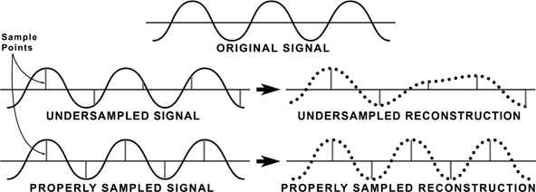
The process of capturing analog sound freqencies as data is called sampling. The theorem that describes how frequently we must sample audio is named after Harry Nyquist, the American physicist discussed in Chapter 11. The theorem states that sampling of a sine wave has to be slightly more than twice the highest frequency in order to be successfully reproduced. If the sampling rate is equal to or less than the original frequency, data will be lost at certain points along the wave. The reproduced signal will be incomplete (Figure 16.3).
Based on the Nyquist theorem, the sampling rate for audio had to be slightly more than 40 kHz, or 40,000 samples per second. The original sampling rate for high quality audio was set at 44.1 kHz. In order to have a sample rate that worked equally across international
video frame rates, 48 kHz was chosen for professional video equipment. For some applications, the sampling rate can be increased to 96 kHz and as high as 192 kHz. Other, lower quality applications can reduce the audio sampling rate by first filtering away the high frequency component of the analog signal. Sample rates as low as 8 kHz can be used for “phone quality” recordings.
Each sample taken is composed of digital bits. The number of bits contained in the sample can vary. A sample can be composed of 8 bits, 16 bits, 20, 24, or 32 bits, and so on. The more bits in the sample, or the larger the digital word used, the truer the reproduction. Both the frequency of sampling and the number of bits contained in the sample are restricted only by the band-width and the speed of the equipment creating or reproducing the data.
Audio Compression
Sampling is part of the digitizing process. Audio, like video, once it is digitized or sampled, can be compressed. The compression process reduces the quantity of data by reducing redundant information. Within the range of human hearing—20 Hz to 20 kHz—the range of 2 to 5 kHz, which is the range of the human voice, is most sensitive. During the compression process, this range is given a higher proportion of the compressed audio data stream. Frequencies above and below this range are more heavily compressed and are allotted a smaller percentage of the data stream.
Audio is typically compressed by a factor of about ten to one. As with video compression, different audio compression techniques are used depending on the sound quality desired and the bandwidth and sampling rates available. The MPEG process of compression is common. Within the MPEG compression process, three data rates are used. Each of these data rates is referred to as a layer.
A layer is a data transfer rate that is based on the number of samples per second and the number of bits contained in that sample. Each of these layers represents a different quality of reproduction. Each layer is compatible with the layer below it. In other words, Layer 1 can reproduce Layer 2 and Layer 3. Layer 2 can reproduce Layer 3, but they are not backward compatible.
Table 16.1
Data Rate Layers
| Layer 1 |
192kbps |
Lowest compression |
| Layer 2 |
128kbps |
Medium compression |
| Layer 3 |
64 kbps |
Highest compression |
Layer 1 is the lowest rate of compression, thereby yielding the best fidelity of the original signal. The bit rate is 192 kilobits per second (kbps), per channel.
Layer 2 is a mid-range rate of compression. The bit rate is 128 kbps per channel. In stereo, the total target rate for both channels combined is 250 kbps per second.
Layer 3 is the highest rate of compression at 64 kbps per channel. Layer 3 uses complex encoding methods for maximum sound quality at minimum bit rate. This is the standard popularly referred to as MP3, which represents MPEG-2 Audio Layer 3.
Noise Reduction
Analog recording on tape created an inherent high frequency hiss. This is caused by the movement of the oxide particles across the audio heads while the tape is in motion. The particles rubbing on the audio heads create a hissing sound, some-what like rubbing sandpaper on wood. The noise is created by a physical phenomenon and is not a recorded signal. It is the nature of the recording medium.
A process of noise reduction in analog recordings was developed by Ray Dolby, an engineer who was also involved in the original creation of videotape recording. Dolby discovered the range of frequencies that comprise this high frequency hiss. He determined that by amplifying the high frequencies in the recorded signal, and then attenuating or reducing those signals to their original levels on playback, the high frequency noise inherent in analog tape recordings could be reduced. If the high frequencies were simply reduced on playback without the first step of amplification, the high frequencies in the signal would be lost. Dolby encoding can be used for any type of analog recording on tape.
Single-Channel, Stereo, and Surround Sound Audio
No matter how sound is recorded, compressed, or reproduced, how it is heard depends on the recording technique that is used. For example, single channel or mono audio, also called monophonic or monaural, consists of a single audio signal without reference to left, right, front, or rear. When played back, mono audio imparts no information as to the direction or depth of the sound.
Other audio recording systems, such as stereo and surround sound, include data that imparts information as to the direction and depth of the sound. Stereo, with discrete left and right channels, more closely resembles the way sound is normally heard. Due to the position of the ears on either side of the head, each ear receives the sound at a slightly different time, allowing the brain to locate the source of the sound. With stereo recordings, the sound is separated so that each ear hears the sound in a natural way, lending a sense of depth and reality.
To enhance this realistic effect, Dolby Labs developed surround sound. Surround sound adds additional channels that appear behind the listener. These are called the surround channels. The term surround sound is a trademark of Dolby Laboratories.
Dolby Digital and Surround Sound
The ATSC adopted a set of standards for the video portion of digital television known as document A/53, introduced in Chapter 12 of this book. The table of standards associated with A/53 does not address audio. Audio standards are set in a document referred to as A/52. Within the A/52 document, the ATSC refers to the Dolby Digital coding system as AC-3. The AC-3 method of coding audio has been accepted by manufacturers as the primary audio coding method to be used for most consumer equipment. Consequently, broadcasters and manufacturers have accepted this standard for production purposes.
Dolby Digital, or AC-3, covers many different variations of audio inputs, outputs and the various channels associated with multi-channel audio systems. As most manufacturers have adopted Dolby Digital as their manufacturing standard, most new consumer equipment contains Dolby Digital decoders. Because of this, professional equipment manufacturers design and build audio equipment to accommodate the Dolby Digital AC-3 audio standard.
As digital data allows for the inclusion of more information than was possible in analog, more channels of audio have been added to further enhance the realism of the audio. The number of channels first was increased to six. This is referred to as 5.1 Dolby Digital, or just 5.1.
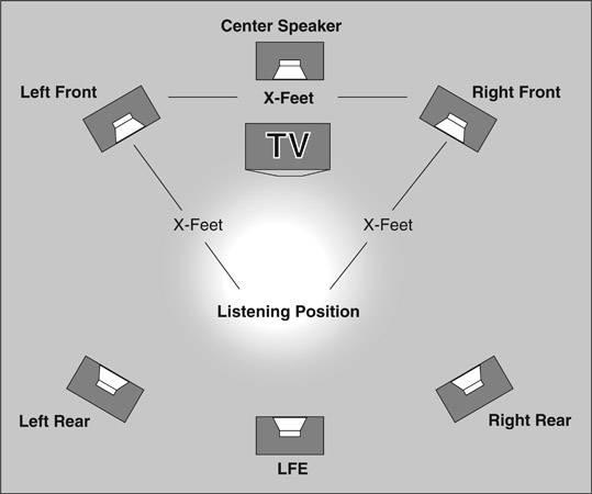
The 5.1 system has five discrete, full-range channels and a sixth channel for low frequency bass. The five full channels are left and
right front, center, and left and right rear (Figure 16.4). The front left and right channels would be the equivalent of the original stereo channels, the center the equivalent of the original mono channel, and the left and right rear the equivalent of the original surround channel. However, these channels now carry far more audio data that adds to the realism of the audio portion of a program. They are no longer as restricted as the older analog systems were. These channels now contain audio data that create an effect of being within the actual environment.
The sixth channel is referred to as the LFE channel, or Low Frequency Effects channel. Because low frequency audio is non-directional, the placement of the LFE speaker is not critical. Low frequency audio, because of its power even at low volume levels, tends to reflect off surfaces and so its direction is not discernible by the human ear. As the LFE channel needs only about one-tenth the bandwidth of the other full audio channels, it has been designated as .1 channel or a tenth of a channel, thereby giving the designation 5.1 channels of audio.
With all these possibilities for creating and recording, the audio channels and their uses must be designated and documented carefully. A video program tape or file may have mono, stereo or multichannel surround. The surround might be discrete channels, or be encoded with either analog or digital encoding. Many programs may have more than one format of audio attached. For example, it is common to have six discrete channels for surround, and two additional channels with a stereo mix.
As part of the drive for more immersive and theatrical viewing experiences, the number of surround channels can be increased. To expand the sound field even further, the 7.1 channel system adds two additional speaker positions to the left and right of the listener.
NOTE NHK in Japan has developed an 8K video system that includes 22.2 channels of surround using layers of speakers above and below screen level.
Out-of-Phase Audio
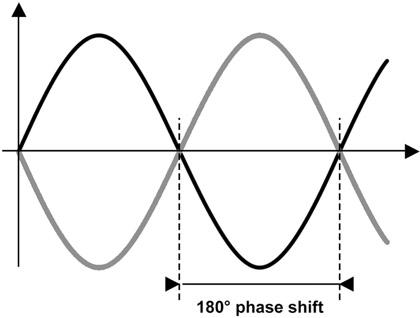
As with any signal based on sine waves, the waves of audio signals can be out of phase with each other. If the waves are 180º out of phase or, in other words, exactly opposite each other, cancellation will take place. When one wave is at its peak, the other would be at its low point (Figure 16.5). The result would be silence or near
silence. Either side listened to alone would sound fine, as two signals are needed to create an out-of-phase situation. Signals less than 180º out of phase also cause a decrease in volume or amplitude but to a lesser degree.
Out-of-phase situations can be detected by a phase meter, a scope, or sometimes just by listening. Listening to one side, then the other, and then both at once, will sometimes allow the detection of an out-of-phase situation. A drop in amplitude, when the two sides are listened to at once, will be an indication that the signals are out of phase.
The out-of-phase error can occur anywhere along the audio chain, from the microphone placement in the original recording to the final playback. The audio may have been recorded out of phase or the speakers may have been wired incorrectly. Correcting this problem can sometimes be as simple as reversing two wires on one side of the signal path. By reversing one side only, the two sides would then be in phase with each other. This switch can be made anywhere along the audio path, and the problem will be corrected.
If the audio is recorded out of phase, this can only be corrected by re-recording the audio in the correct phase relationship. It is possible to play back out-of-phase audio and, by phase reversing one side of the signal path, correct the phase for playback purposes.
Some digital scopes have a selection for checking stereo audio. If audio is present in the SDI stream, the signal will appear on the scope. If the audio is stereo and in phase, it will appear as a straight diagonal line. If audio is out of phase, the two lines appear separated by the amount they are out of phase.
Measuring Audio Phase
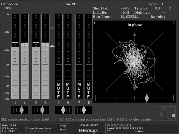
Some digital scopes have a selection for checking stereo audio using a display called a lissajous pattern. If the audio is in phase, it will appear to orient along an axis on the scope marked “in phase” (Figure 16.6 (Plate 23)). Should the audio be out of phase, it will tend to orient to the axis that is 90º to the in-phase line. The greater the difference between the channels (or the more stereo the content), the more confused the display appears. It is difficult with very different material to be certain if the signal is falling in or out of phase on the scope.
A second feature on the scope in Figure 16.6 shows another useful phase tool. This one helps determine phase with stereo audio that has very different content. The feature is called a Correlation Meter and is represented by a diamond. On the display shown in the figure, there are 5 different Correlation Meters (shown as diamonds),
one below each stereo pair of meters, and one below the lissajous display of the signal. The diamond shaped indicator shows how much the channels in the measured stereo pair are similar, or correlate. If they are exactly the same and in-phase, the diamond will move to the far right of the display. If they are completely different, and therefore have no phase relationship, the diamond will fall in the center of the display.
Properly phased stereo audio will cause the diamond to drift between the center and right side of the meter. Out of phase audio will cause the diamond to begin to move to the left of the center mark, and many scopes will turn the diamond red. The greater the phase error, the further to the left the diamond will move.
Transporting Audio
When working on large scale video productions, there are several common ways to manage and move audio signals both in analog and digital form. Many people, having been in or worked around music performances, may be familiar with the analog method using twisted pair wiring. Each individual audio signal, like microphones or instruments, is carried to mixers and amplifiers on a pair of wires that are twisted together to reduce interference. Often when there are many signals to move around, say between a stage connection box and the mixer, multiple sets of wires are bundled together in “mults.”
With the advent of digital signals, several other forms of moving the audio portion of the program became possible. One option is called embedded audio. In this system, the uncompressed audio signals are inserted into the digital data stream along with the video signal and other metadata. This is very convenient as a single cable can carry up to 16 channels of digital audio right along with the picture information. (Figure 4.1, Plate 1 shows the digital audio signal in a pulse cross display.)
In large TV productions, however, audio is often handled by different departments and equipment right up to the time it is handed off to the people who will oversee its transmission to air, cable or web. In those cases, it is not efficient or possible to work with the audio that is embedded with the video portion of the program.
Currently the most popular format in these situations is called AES, which is shorthand for the signal format AES 3, or AES/EBU. AES is the Audio Engineering Society, a standards group interested in all things audio. EBU is the European Broadcasting Union, a standards group that deals with broadcasting in the European
Union (you can read more on standards in Chapter 12). This standard dates back to 1985 and describes a system of encoding digital audio signals in a way that is compatible with the needs of audio and video systems. In 1985, stereo audio was the most prevalent form of listening, so the AES bundled its two channels together into a single stream. As a result, one “channel” of AES contains two signals, both the left and right portions of a stereo pair of analog channels (Figure 16.7).
AES was designed to work with the existing analog system, so it was designed from the outset to be carried on either twisted pair wire, like analog audio, or on the kind of coax that video signals use. This made it easy to transition to digital audio as existing wiring and patch bays could be repurposed to carry the AES signal. It is also possible to carry the signal on fiber optic cable, and on consumer grade cable and connections.
NOTE When used in consumer equipment on copper cable, it is called S/PDIF (Sony/Philips Digital Interface Format). TOSLINK is the consumer name for the fiber optic connection. TOSLINK is shortened from Toshiba Link.
The AES did not stop with just that one format. There is another format that is quite common in large productions known as AES 10 or, more commonly, MADI (Multichannel Audio Digital Interface). As the name implies, this digital standard is designed to carry many more channels than the stereo pair of AES 3. Using MADI, up to 64 channels of audio can be carried on a single cable, either copper coax or fiber optic. This format is used to connect devices that require a lot of audio channels to be connected to each other, such as hooking the studio routing system to the audio mixer. It is also a really handy way to deal with the stage box idea. By putting a MADI breakout box near the source of audio signals, a single coax or fiber cable can be run back to the audio mixer. Imagine the savings in time laying one cable to the floor of the basketball arena from the TV truck instead of five or six mults!
Taking the idea of reduced wiring for multi-channel applications and applying computer networking techniques leads to another interesting way to move audio signals. Audio over Ethernet encodes audio signals using the standards and conventions of computer networking. There are several different proprietary formats for this. As of the writing of this book, CobraNet and Dante were very popular.
With these techniques, several hundred individual audio channels may be carried over standard network cabling and distribution equipment. Now distributing and collecting audio from large venues is as simple as connecting a network cable. As most of the infrastructure of television is migrating toward computer based technologies, this will likely become the dominant method for audio connections in the near future.


