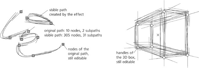
Path effects are an easy-to-use (for the end user) yet powerful (for the developer) mechanism for implementing modifications of the visible shape of the path—for example, rounding all corners, roughening it, blowing or pinching it. No matter which path effect you apply to a path, the original path before the effect can still be viewed and edited—and after you edit the original path, the visible path is automatically recalculated from it and from the effect parameters.
Thus, path effects in Inkscape are another example of the basic principle of vector graphics: Instead of making some permanent and destructive change, leave the original object unchanged and just record the way this change is to be applied. After that, both the original object and the parameters of the change applied to it can be edited separately at any time.
Path effects, despite the name, apply not only to paths but also to shapes (Chapter 11) which remain shapes and are still editable as such, using the handles or numeric parameters in their shape tools. Path effects don’t, however, apply to text objects, clones, or bitmaps. A path effect can be applied to a group, which gives the same result as if the effect was applied to all paths and shapes in the group combined (i.e., made subpaths of a single path).
When a path effect is applied to an object, the only aspect that changes is the visible shape of the object; if you want to change its style in a nondestructive way, try filters instead (Chapter 17). Path effects can be stacked on top of one another, so that the output of one effect is an input for the next one.
SVG
Live path effects are an Inkscape-only feature; unlike, for example, filters, path effects are not part of the SVG standard. However, they are implemented in an SVG-compatible way: If you load an SVG file using a path effect into an SVG viewer (or into an old version of Inkscape that did not support this effect), you will see the same visible path that you see in Inkscape, but without access to the original path and the effect parameters. There’s a caveat: If you try to edit that visible path in a version of Inkscape that does not support the effect and then reload the changed file into a newer version that does support it, your changes will be lost because the new visible path will be generated from the unchanged original one and the effect parameters.
In a path element with a path effect applied, the original path data is stored in the inkscape:original-d attribute. The path’s effect is specified in the inkscape:path-effect attribute, which refers to an element with the same name stored, along with its parameters, in the defs of the document (A.4 Defs, View, and Metadata). The result of the effect is automatically recalculated and stored in the standard d attribute of the path object. All Inkscape tools and commands know that, in a path with a path effect applied, they should not edit or change the d but work on, or display, the inkscape:original-d instead.
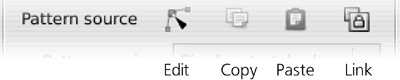
To assign one object’s path effect to any number of other paths or shapes, copy the source object ( ), select the target, and use the Paste Path Effect command (
 ). Inkscape comes with a number of sample SVG files (in /usr/share/inkscape/examples on Linux, <inkscape-dir>\share\examples on Windows), some of which demonstrate various path effects; you can use this copy/paste trick to reuse the effects from any of these sample files in your documents.
When you combine (12.1.1 Subpaths) shapes or paths, the result will have the path effect of the topmost object, if any. Breaking apart a path with a path effect causes the effect to be applied to all resulting new paths.
To clear away the path effect and return to the original path, use the Remove Path Effect command in the Path menu. If, however, you want to preserve the result of the effect and forget the original path, use the Object to Path command ( ); this will not change the way the path looks, but the effect will be gone.
SVG
The Object to Path command is also the best way to ensure that your file is not only correctly rendered but also editable in older versions of Inkscape and in SVG editors other than Inkscape.
With the Node tool, you are editing the original path, not the visible path after the effect. Since the path you’re editing is not visible by itself, it is convenient to highlight it using the corresponding toolbar button (Figure 12-17); most effects will enable this highlighting automatically for you.
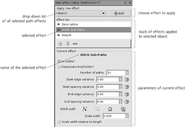
The Path Effect Editor dialog ( , see Figure 13-2) is the main control hub of path effects. It lists all path effects supported by Inkscape (this list expands with each new Inkscape version) and lets you choose those to apply to your selected path, shape, or group. When an object with one or more path effects is selected, you can use this dialog to view its stack of effects, add or remove effects, and adjust the parameters of the selected effect.
Note
If you have applied some path effects to a group, you can edit those effects’ parameters only when you select that group, not when you select any of the paths in it.
The Effect list in the dialog lists all the effects applied to the selected object. They are listed top to bottom; that is, the first effect applied to the source path is the topmost one, its output is passed to the second one, and so on until the last listed effect whose output is displayed.
A new effect you add is placed at the end of the stack. You can move any effect in the stack up or down by the arrow buttons below the list. The eye icon before each effect’s name allows you to disable an effect, forcing Inkscape to bypass it (the Is visible? checkbox in an effect’s parameters has the same function). To delete an effect from the stack, use the button with the minus sign.
Parameters of an effect can belong to several types:
Numbers can be either integers or fractional, depending on the nature of the parameter. When a number denotes a distance, it is usually in
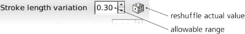
pxunits (A.6 Coordinates and Units).In random number parameters, the editable number specifies the range in which the random values must fall, and the dice button reshuffles the random values controlled by this parameter:
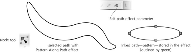
Link parameters are used when one path’s effect uses some other path as one of its parameters. That linked path can be a separate object located somewhere on the canvas (in the same document), or it can be a path stored entirely within the path effect and not visible in the document.
A link parameter displays a row of four buttons:
Edit button
Switches Inkscape to the Node tool and lets you edit that linked path, regardless of whether it’s a separate object or a path stored inside the effect (Figure 13-5). In the latter case, that path is shown as a green outline.
This is the same as if you switch manually to the Node tool and click the Edit path effect parameter button on the controls bar.
Copies the linked path to the clipboard.
Paste button
Pastes the path from the clipboard into the effect, making a copy of the clipboard path and storing it in the effect.
Link button
Takes the path copied to the clipboard and links the effect to its original in the document. Now, editing the object you had copied will change this path’s effect.
Apart from the numeric controls in the dialog, some path effects allow you to edit their parameters visually by on-canvas handles accessible in the Node or shape tools. We will see examples of this as we discuss specific effects.
The Pattern Along Path and Bend effects are very similar. They both take one path (called the pattern) and bend and/or stretch it along another path (called the skeleton). This is very similar to “skeletal paths” in software such as Microsoft Expression, typically used for freehand drawings (see Figure 14-11).
As usual with path effects, both the skeleton path and the pattern remain editable at any time, with the result updated live. This is a great way to create easily editable vector brushes—for example, you can start by creating a drawing with the Pen or Pencil tools, and then try applying various patterns to all its paths, adjusting the widths for the best result.
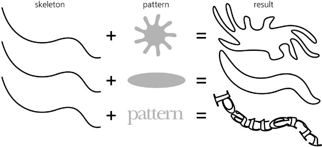
Aside from the ability to repeat a pattern, the main difference between the Pattern Along Path and Bend effects is which path is the skeleton and which is the pattern:
In Pattern Along Path, the path you’re applying the effect to becomes the skeleton, and the pattern is linked up using a link parameter. This effect is ideal for simple, possibly repeated patterns applied to arbitrary skeletons. The linked pattern path can be either an independent path object in the document, or a path stored inside the effect itself. The result gets the style of the skeleton. This is the effect used by the Shape option in the Pen and Pencil tools (14.1.5 Stroke Shapes).
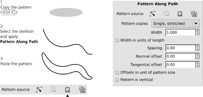
Once you apply Pattern Along Path to a skeleton path, you need to supply the pattern using the Pattern source link parameter. The Edit button does not work unless you paste or link some pattern path first, so the usual sequence of operations is this: Select a pattern path, copy it (
), select a skeleton path, assign Pattern Along Path to it, and paste or link the pattern to it. Or, you can quickly draw skeletons with the copied pattern applied to them automatically if you choose From clipboard in the Shape list in the Pen or Pencil tools.In Bend, the path you’re applying the effect to becomes the pattern, whereas the skeleton is linked up using a link parameter. This is more convenient when you have a complex pattern that you want to lightly curve along a simple, possibly shared skeleton path. Similarly, the linked skeleton path can be either an independent path in the document or a path stored inside the effect itself. The result gets the style of the pattern.
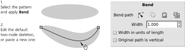
For this effect, you start with the pattern and use the Bend link parameter to link to a skeleton. Unlike Pattern Along Path, however, Bend provides a default two-node skeleton path that stretches along the horizontal axis of your pattern—so you can at once use the Edit button to edit that skeleton. If you prefer, however, you can still paste a skeleton from the clipboard or link to the copied path.
Note
You can use any path for an external linked skeleton with Bend, including a path with some other path effect applied to it.
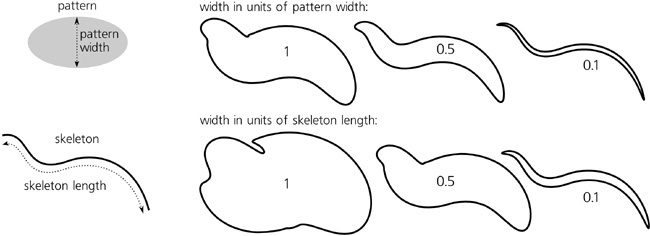
Both effects allow you to change the width of the pattern. This width can be measured either in the units of the original width of the pattern or in the units of the skeleton length:
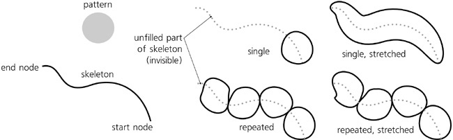
The Pattern Along Path effect can use one of the following repeat modes:
Single
Places a single copy of the pattern along the skeleton, from start node, without stretching it. So, if the pattern is shorter than the skeleton, it will only cover part of the skeleton length; if the pattern is longer (i.e., does not fit even once), it will not be applied.
Single, stretched (default)
Also places a single copy of the pattern along the skeleton, but always stretches or squeezes it so it exactly fits the skeleton length. The Bend effect always uses this mode; unlike Pattern Along Path, in Bend the repeat mode is not changeable.
Repeated
Places as many copies of the pattern along the skeleton as fits the skeleton length, but does not stretch them, so the remainder of the skeleton length less than one pattern length remains unfilled. (However, this does not mean that the copies of the pattern are identical; the curvature of the skeleton may noticeably distort them, as Figure 13-10 demonstrates.)
Places as many copies of the pattern along the skeleton as would fit and stretches them evenly, so that they exactly fill the entire skeleton length.
The pattern always starts from the start of the path; if you want it to go the other way, use Path ▸ Reverse.
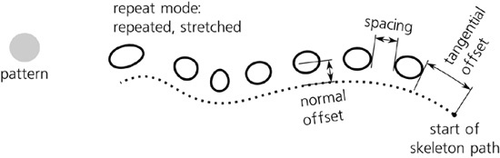
Also, the Pattern Along Path effect allows you to adjust some distance parameters:
Spacing (only for repeated modes)
Sets the spacing between copies of the pattern on the path.
Normal offset
Moves all copies of the pattern perpendicular to the skeleton path at each point.
Tangential offset
Moves all copies of the pattern along the skeleton path, starting the first pattern not at the start of the skeleton but this specified distance from it.
These offsets and spacing parameters are, by default, in absolute px units. By checking the Offset in units of pattern size checkbox, you can express them as multipliers of the pattern size—for example, a tangential offset of 0.5 will shift the pattern along the skeleton by half of the pattern’s width.
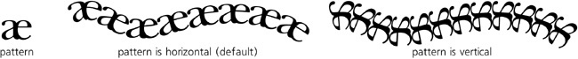
By default, the original of the pattern is considered to be horizontal—that is, the pattern is aligned on the skeleton by the pattern’s horizontal axis. By checking the Pattern is vertical (for Pattern Along Path) or Original path is vertical (for Bend) checkboxes, you can rotate the pattern by 90 degrees so that it’s aligned on its vertical axis, as shown in Figure 13-12.
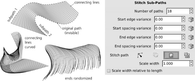
The surprisingly useful Stitch Sub-Paths effect works only for paths with two or more subpaths (12.1.1 Subpaths). It replaces the source path with a lattice of paths connecting equispaced points on the subpaths; you can set the number of the connecting paths via a parameter. With this effect, you can create all kinds of hair, fur, lattices, moiré patterns, or “power fields”:
Note
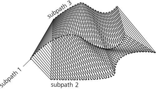
If the path has three or more subpaths, each pair of subpaths gets its own connecting lattice. This means that the number of connecting lines literally explodes as you increase the number of subpaths in the original—so don’t try this effect on a path with more than a few subpaths, or you will easily bog Inkscape down to a halt!
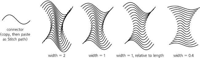
The connecting lines need not be straight, although that is the default. You can use the Stitch path link parameter to paste or link any existing open path to serve as the stitches, or you can edit the lines with the Node tool. The Scale width parameter scales the stitch path in the direction perpendicular to its start-end direction (the value of 1 gives it its natural width). The Scale width relative to length makes the width of each stitch depend on the length of this stitch, as shown in Figure 13-15.
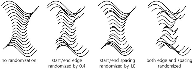
Finally, a group of randomization (variance) parameters allows you to shuffle the attachment points of the stitches, both along the path (spacing) and perpendicular to it (edge), separately for the beginning and end of each stitch:
This effect breaks a path into subpaths, creating gaps between them where the path (or a group of paths) self-intersect. It can turn a stroked path with self-intersections into a Celtic knot:
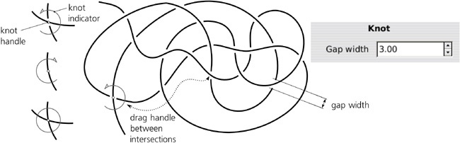
The only numeric parameter for this effect specifies the width of each gap in px units. On canvas, you can control each intersection individually. Select a path with the Knot effect, switch to the Node tool, and notice that one of its self-intersections has a diamond-shaped handle and a green circular indicator which is open on one side. Click that handle; the indicator flips to the other side and the gap now affects the other line at the intersection. Click it again and you close the intersection removing any gaps; the indicator is now a solid circle. You can cycle through these three states of an intersection by clicking the handle. To control another intersection on your path, just drag the handle and drop near the intersection you need.
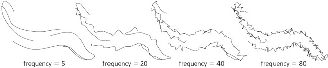
Sketch is a complex artistic effect that turns a path into a sketch-like drawing with multiple strokes, as if hand-drawn by an artist who was trying to find the best shape:
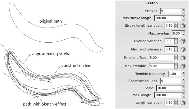
To make sense of the plethora of parameters of this complex effect, remember that the sketch consists of two types of artifacts: approximating strokes and construction lines. The approximating strokes cover the entire path; they are typically curvilinear, more or less parallel to the original path (with certain tremor), and travel at some distance from it. The construction lines, on the other hand, identify and emphasize straight or almost straight parts of the path by drawing straight lines that extend on both sides.
For the approximating strokes, you can change:
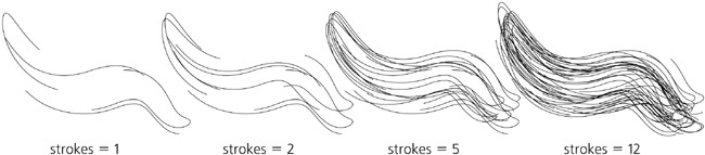
The average number of parallel strokes at each point of the path (the default is five). Set this parameter to 0 to hide approximating strokes (leaving only construction lines); low values make the sketch airy and tentative, increasing the number makes it bolder and noisier:
The maximum length of strokes (in
pxunits) and the range of the random length variation (relative to the maximum length).The maximum overlapping of subsequent strokes (in
pxunits) and the range of the random variation of this parameter (relative to the maximum overlap value).The end tolerance affecting how close the approximating strokes follow the original path.
The average offset of the approximating strokes from the original path; by varying this parameter, you can make the sketch either neat and tight or wide and ruffled.
The maximum tremble and its frequency; these control how the strokes oscillate around the original path. Increasing the maximum tremble ruffles the sketch, similar to increasing offset but more randomly; increasing the frequency makes the sketch lines look rougher by making them tremble on a smaller scale.
For the construction lines, you can change:
The total (not average) number of the lines in the sketch (the default is five). Set this to 0 to suppress construction lines, leaving only approximating strokes.
The scale parameter tells how far the ends of the construction lines can go beyond the ends of the straight (or approximately straight) parts of the path.
The maximum length and its random variation set the upper limit on the length of construction lines:

Building paths with Bézier curves (12.1.4 Bézier Curves) has many years of tradition behind it. All modern graphics software worth its salt supports it in much the same way, and millions of users are familiar with it. The Bézier paradigm is, undoubtedly, extremely flexible and powerful. I think most people who have ever used it will find it difficult to name any major disadvantages specific to it.
And yet, once you try something better, these disadvantages become painfully obvious.
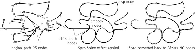
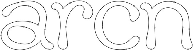
Spiro splines are a novel way of defining curvilinear paths, developed by Raph Levien. They take some getting used to, but for certain tasks (such as lettershape design) Spiros have a clear advantage over Bézier curves. Since version 0.47, Spiro splines are available as a path effect in Inkscape, which means you can use all the convenient Inkscape path tools (such as moving and transforming groups of nodes, node sculpting, etc.) on Spiro paths. The Pen and Pencil tools can produce Spiro paths directly (14.1.4 Modes).
A Spiro path is defined by a sequence of nodes. However, unlike a regular path consisting of Bézier curves, all Spiro nodes lie on the path, and there are no off-path handles. The curvature of the path is defined entirely by the positions of the nodes and their types. The path behaves very similar to a springy rod that is forced to pass through the given points and which uses the minimum possible curvature to satisfy the requirement:
Once you get the basic idea, the Spiro behavior will feel more and more natural as you’re getting used to it. More importantly, the resulting path is always very smooth—not just superficially smooth, as in having no cusps, but smooth at a deeper level, which you can only achieve with Béziers after a lot of laborious tweaking.
After a Spiro experience, it becomes clear that the main problem with Béziers is each node having not only a position but also its own intrinsic “direction” and “curvature,” as defined by its handles. So, whenever you move a Bézier node around, you also need to carefully adjust its handles so the curve still looks smooth and natural. With Spiros, you are freed of this requirement; just move the node wherever you want the curve to go, and the smoothness of the curve is taken care of automatically.
Note
After a Spiro path is converted to a regular path, it gets two to three times as many nodes; now, consider that each of these Bézier nodes are actually three points (the node itself and its handles) compared to just a single point of a Spiro node—and you will get an idea of how much faster and easier Spiro path editing can be.
To create a Spiro path, select any path and assign the Spiro spline path effect to it. There are no parameters. Each node of your path becomes a point of a Spiro path, depending on the type of node (12.5.5 Node Types):
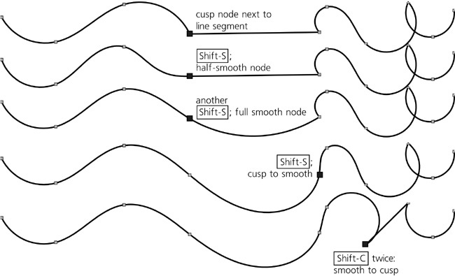
Smooth nodes (those with two collinear Bézier handles) are smooth points on the Spiro path. Note that the length and direction of the Bézier handles on the source path are ignored; the only thing that matters is their collinearity (i.e., smoothness). Press
 to line up the handles of the selected node to make it smooth.
Half-smooth nodes (those with one Bézier handle collinear with a straight line segment on the other side) behave exactly the same on a Spiro path: They sit between a straight line and a curve and enforce that these two segments join smoothly without a cusp. If you have a straight line segment on one side of a node, the first
will make it half-smooth.Cusp nodes on the source path become corner points of the Spiro path. They behave like free hinges on the springy rod, allowing it to bend at any angle. Between two corner points, the Spiro path is always a straight line. To make a node cusp, press
 twice (the first just changes the type of the node and the second actually retracts the handles).
Note
What matters for Spiro is the actual collinearity of a node’s handles, regardless of the node type that the node has in the Node tool. For example, if a node designated as cusp (diamond-shaped) has collinear handles, it will still be a smooth curve point on the Spiro path.
Probably the biggest problem with Spiro splines is that some configurations of points are unstable and produce wild loops and spirals instead of a smooth curve. Still, sensible sequences of points usually work fine; you just need to avoid sharp changes in direction between points to prevent such instability. Hopefully, the robustness of the algorithm will be improved in future releases.
When editing Spiro paths with the Node tool, the red highlight of the source path may be a distraction; you can turn it off with a toggle button in the controls bar.
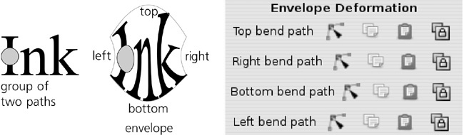
This effect distorts a path or a group of paths by fitting them into a curvilinear envelope. After you apply the effect, the envelope is rectangular, and you can curve its sides one by one by the Node tool. The effect treats all four sides as separate helper paths (“bend paths”), which is slightly inconvenient: You need to click the Edit buttons for each side in turn to curve all four sides. The Copy and Paste buttons allow you to transfer the exact shape of the envelope from one object to another.
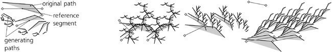
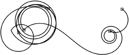
This fractal-like recursive effect takes the original path and repeats it twice (as subpaths) with shifting, scaling, and rotating; it then repeats the same operation on these copies, and so on for the specified number of generations. The transforming of the copies is determined by the configuration of three helper paths: a reference segment (initially, horizontally across the source path) and two generating paths (initially, horizontally across the two first-generation copies). These helper paths are two-node straight line segments (i.e., their curvature is disregarded); to edit them, you can use the Node tool and click the Edit path effect parameter button on its control bar once or twice; or, you can click the Edit button in the effect’s parameters for the corresponding helper path. Here are some examples: