A path is a sequence of nodes (points) connected by straight or curved segments (Figure 12-1). Each node may have either one neighboring segment (if it’s an end node) or two (if it’s a middle node); SVG does not allow you to have branching paths with more than two segments joined at the same node.
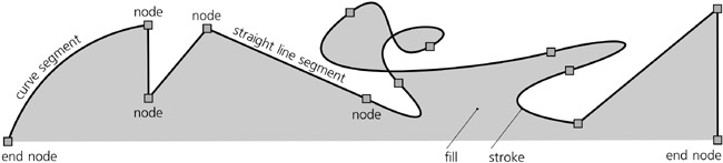
The length of a path is not limited; it may have anywhere from two to many thousands of nodes (although paths that are too complex are slow to render and therefore should be avoided).
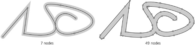
With a path, you can at least approximate (and in many cases, reproduce exactly) any conceivable shape, form, or figure. Depending on the shape you need and the required precision, in the worst case you’ll just have to use many densely positioned nodes.
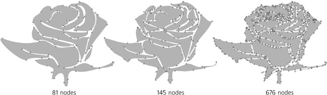
Figure 12-2. The same figure can be roughly approximated with a few nodes or reproduced more precisely with more nodes.
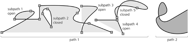
In a path, a pair of nodes that are adjacent in sequence may not be connected by a segment. This produces a gap in the path, and each such gap divides the path into disconnected parts called subpaths, as shown in Figure 12-3.
A path without any gaps is said to consist of a single subpath. Any subpath, just like a piece of rope, can be open (with two loose ends, called end nodes) or closed (tied into a loop, so that its end nodes are one and the same node).
In many respects, subpaths look and behave just like separate paths. You can always convert subpaths of a path into independent path objects by using the Break Apart command in the Path menu. The opposite command, Combine, converts several selected paths into subpaths of a single path.
When combining paths with different styles, you will lose the styles of all but the topmost (in z-order) selected path—because a single path, with no matter how many subpaths, can only have a single style. However, no path data will be lost or added: If you combine and then break apart any number of paths, their nodes will be exactly the same as before.
Every subpath has a direction—that is, its nodes are always ordered from start to end. In a closed subpath, the start node and the end node are the same node; in an open subpath, start and end nodes are different. Usually, the direction of a subpath does not matter, but it determines positioning of the start and end markers (9.5 Markers) and text on a path (15.2.3 Text on a Path). The direction may also affect the fill of the path via the winding rule (12.1.2 Filling Paths). Use Path ▸ Reverse ( ) to flip the direction of the selected path or paths.
No matter what you use to fill your path—solid color, gradient, or pattern (8.1.1 Paint)—there are several important things to be aware of.
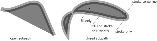
Fill always stops at the path itself—that is, at the center line of the path’s stroke, if it has any. Closed subpaths that do not intersect themselves or other subpaths are simply filled on the inside. Open subpaths are filled as if there’s a straight line segment between the end nodes of the subpath:
Note
Remember that this straight line is not part of the path; it is not stroked and you cannot, for example, bend it with the Node tool. If, when editing an open nonstroked path, you run into a straight line segment that refuses to be edited as you expect it to, most likely it’s not really a segment but simply an edge of the fill. Close the subpath (12.5.4 Joining and Breaking) to edit it without limitations.
When a path intersects itself or when one subpath is completely inside another, the decision on whether to fill some area depends on two factors: the directions of the subpaths surrounding the area and the fill rule of the path. The fill rule is a style property that can take one of two values, nonzero or evenodd, as set by one of the two toggle buttons in the Fill and Stroke dialog (see Figure 8-2):
With the fill rule value of
evenodd, holes and loops are always left unfilled, except when you have a hole within a hole; then the inner hole becomes an island of fill.The fill rule value of
nonzeromeans that a loop or hole is filled only if its boundary is counterdirected relative to the outer path and is empty if they go in the same direction.
With the fill rule of nonzero, those loops and holes that are filled are therefore invisible unless the path is stroked. Usually they are not a problem, but sometimes you may want to get rid of them. The easiest way to do that is to select that one path and use the Path ▸ Union command ( ). Unioning a path with itself removes all subpaths that do not affect its fill.
There’s no way to reverse the direction of a single subpath inside a path. If you need to do that, you’ll have to Break Apart the path (12.1.1 Subpaths), reverse one of the resulting paths, and Combine them back into a single path.
The stroke of a path is a strip of paint that goes along the path itself, so that the path marks the centerline of the stroke. The stroke is painted on top of the fill, if there is any. There are many style properties that affect the look of a stroke; they are covered in great detail in Chapter 9.
The Path ▸ Stroke to Path command ( ) converts the stroke of the selected path into fill. In other words, it replaces it with a new path whose fill looks exactly the same as the original path’s stroke, honoring all the join, cap, miter, and dash properties of that stroke. The stroke paint of the original becomes the fill paint of the new path, whereas the original path’s fill is discarded. If the original path had markers (9.5 Markers), the result will be a group where the stroke converted to path is grouped with markers that are now separate objects.
As already mentioned, segments—parts of paths between the nodes—can be either straight or curved. Now, let’s have a closer look at those curved segments, called Bézier curves after Pierre Bézier (1910–1999), a French engineer who was the first to use them in design.
A Bézier curve is completely determined by the position of four points, two of which are the nodes and two of which are the handles, or controls. The curve itself is always completely inside the quadrilateral of these four points. In the Node tool (12.5 The Node Tool), each of the handles is connected with its node by a straight line. These handle lines are always tangential to the curve at the corresponding node:
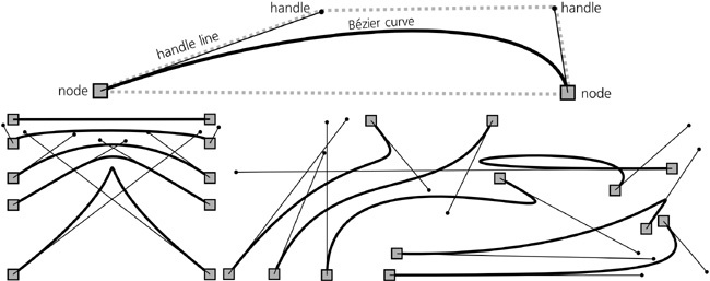
Note that in a path, if a node is between two Bézier curve segments, it will have two handles connected to it, one for each adjacent segment.
The way a Bézier curve reacts to moving its handles is hard to verbalize, but you will quickly get a feel for it once you experiment a little. A Bézier curve may be indistinguishably close to a circular arc, but it may also have sharp bends, almost cusps; it may self-intersect or be perfectly straight when the handles are fully retracted (i.e., coincide with their nodes).
Of course, for all its versatility, not many shapes are possible with a single Bézier curve. When building a path to approximate something (e.g., when manually tracing over a bitmap, 18.8.2 The Trace Bitmap Dialog), experience will tell you how far you can reach with the next Bézier curve and where best to place the next node. Forcing a path to more closely approximate some real-life shape usually involves subdividing its Béziers by adding nodes and adjusting their handles. In contrast, simplifying a path, either manually or with the Simplify command (12.3 Simplifying), usually reduces the number of nodes and results in longer Bézier curves.