The Pen tool is for those situations where you know more or less exactly where you want to place the nodes of your path. It can be thought of as a sibling of the Node tool (12.5 The Node Tool), except it is optimized for creating and connecting nodes instead of editing them.
Switch to the Pen tool ( or
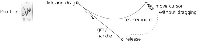
or  ), click and drag on the canvas. The first node of a new path appears where you clicked; the gray straight line between that point and your current mouse position is the handle of this node (12.1.4 Bézier Curves). As soon as you release the mouse button, the handle is fixed—but the path is not finished; it now expects you to click or click-and-drag for a second node. In this mode, just moving the mouse around (without clicking) displays a red Bézier segment that shows you how the path would look if you create the next node at this point.
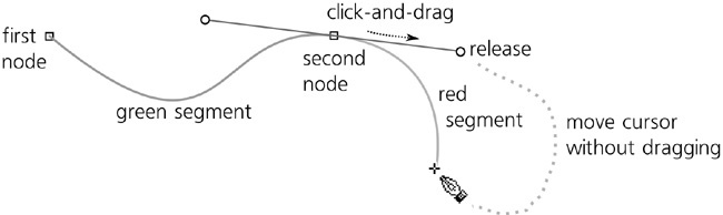
Now, click and drag for the second node (Figure 14-3). After you release, the part of the path between the two defined nodes becomes green, and you once again have a red segment between the last created node and the current mouse point. This can be repeated indefinitely—just keep clicking and dragging (for smooth symmetric nodes) or just clicking (for cusp nodes); on each step, the path you have created so far is green, and the segment you are about to create is red.
To finish the path, double-click or right-click (this adds one more node and finishes the path) or press  (this cancels the red segment without adding any more nodes and finishes the path). It is only at this point that the entire path is actually created as an object; what you saw until now was just a virtual scaffold. Another way to finish a path is to close it; if you create the next node exactly over the first node of the path (which is marked by a little square anchor), the path will be closed and finalized.
To cancel creating a path at any time, press  or simply switch to another tool.
Note
Most key and mouse shortcuts for zooming, scrolling, and panning (Chapter 3) work in the Pen tool without disrupting path creation. For example, you can middle-drag the canvas and middle-click to zoom in so you can better position your next node.
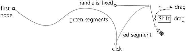
As you’ve just seen, click-and-drag creates a smooth node with two symmetric handles (unless this is a first node of a path which only has one handle). A simple click creates a cusp node without any handles. You can also create cusp nodes with noncollinear handles; for this, click-and-drag but press  while dragging. This fixes the opposite handle and lets you move the near handle independently:
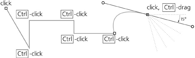
You can also press  while dragging a handle to snap it to 15 degree increments (compare 6.3 The Selector: Rotating and Skewing; you can choose another snap value in Inkscape Preferences). Pressing while moving the mouse around between creating nodes will similarly snap the direction between the last created node and the mouse point; this is an easy way to create strictly horizontal or vertical lines:
You can always step back in your path creation process; to cancel the last added green segment, press  . You can press repeatedly to remove several segments; removing the last remaining node cancels the entire path.
It is not always easy to click exactly where you want the node to appear on the first attempt. Inkscape allows you to move the last created node (i.e., the end of the green segment) without finalizing the path; just use the arrow keys with the same convenient modifiers as in other tools:  to move by 1 screen pixel, to move by 10 times the distance (6.5.1 Moving).
With the Pen tool, any single selected path displays its end nodes, if it has any (i.e., is open), as little squares called anchors. (This applies to any path you just created with this tool itself—after finalizing, it remains selected.) These anchors allow you to continue adding to the selected path (by placing your first node in the anchor) or to close it (by penning from one anchor to the other).
You can also add a new subpath (12.1.1 Subpaths) to the selected path. To do this, just hold down while you click to create the first node. After that, create and finalize the path as usual; your path will be added as a subpath to the selected path. All open subpaths of the selected path show anchors, which means you can close them or connect them to one another:

Now, let’s have a look at the controls bar of the Pen tool (above the canvas). Notice the four Mode buttons:
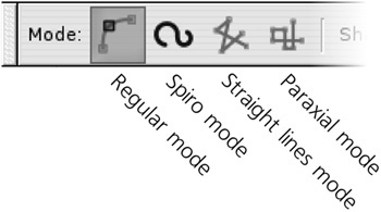
These buttons control the type of path Inkscape is creating. So far we have worked in the first (default) mode, which creates regular paths out of straight lines and Bézier curves.
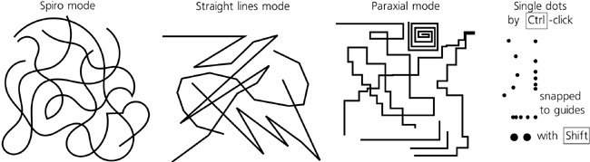
The second mode creates Spiro paths (13.1.7 Spiro Spline), that is, paths with the Spiro Spline path effect applied. In a Spiro path, the exact positions of the node’s handles are not important; the only thing that matters is whether the node is smooth (with collinear handles) or cusp (without any handles or with noncollinear handles). Therefore, in this mode it makes no difference where or how far you drag the handle of a node you create; all that matters is whether you drag it at all (this creates a smooth Spiro node) or just click (this creates a cusp Spiro node).
Note
Unfortunately, in Spiro mode the green and red segments you see while creating a path do not correspond to how the finalized path will look—they show you the path without the Spiro Spline effect applied.
The two other modes are restrictions of the regular mode. The Straight lines mode disables creation of smooth nodes (i.e., it makes sure that even a drag works as a click, creating a cusp node without handles). The Paraxial mode additionally restricts the segments to horizontal and vertical, ensuring that each segment is perpendicular to the one that precedes it.
Also, in the Straight lines and Paraxial modes, -click creates a single dot (a little circle) instead of starting a path. This is convenient for creating geometric and technical drawings. The size of -click dots can be set in the units of stroke width in the Pen tool’s preferences (double-click the tool icon in the toolbox to access its tab in the Inkscape Preferences dialog). If you use  , the dot is twice as big.
The Shape drop-down menu on the Pen tool’s controls bar lets you choose the stroke shape for the path you are creating.
By itself, SVG does not support shaped strokes; in SVG, a stroke is always a constant-width strip (Chapter 9). This is why there’s a difference in behavior between the default None and the rest of the stroke shapes in this list.
With None, you get the barebones SVG path with a plain, constant-width stroke; the path may or may not have a fill inside it, depending on the style the tool uses (14.1.6 Style). With any other Shape option, the tool applies the Pattern Along Path effect to your path (13.1.3 Pattern Along Path and Bend) so as to imitate a shaped stroke by the fill of the path. Therefore, you cannot have any other fill inside the path when using these options, and the tool automatically applies the style of stroke to the fill and discards the original stroke style so the result looks as expected (see Figure 14-9).
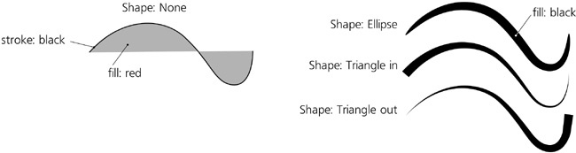
The available stroke shapes include Ellipse, two triangles (Triangle in means the width decreases from the beginning to the end of the path, Triangle out means the width increases from beginning to end), and any other shape you placed on the clipboard if you select the From clipboard option.
To adjust the width of the shaped stroke, open the Path Effect Editor dialog (13.1.2 The Path Effect Editor Dialog) and use the Width control of the Pattern Along Path effect. This parameter can be set either as a multiple of the shape’s natural width (which for all three standard shapes is 10 px) or as a multiple of the path length.
In the Node tool, normally, it is the original skeleton path that is editable, not the shape applied to it, but you can also use the Edit path effect parameter button to edit the applied shape (Figure 13-5).
Path shapes work with any of the modes of the Pen tool, including Spiro. For example, you can draw a Spiro path with the Ellipse shape, then switch to the Node tool and adjust the Spiro nodes—and the entire elliptical shape will bend and curl exactly as a Spiro does. In the Path Effect Editor dialog for this path, you will find both Spiro Spline and Pattern Along Path effects stacked on top of one another.
To turn a path with a shape and/or Spiro Spline applied into a regular path, use the Object to Path command ( ).
).
Like all object-creating tools, the Pen and Pencil tools can either use the last set style or their own tool style (11.1.2 The Style of New Shapes). By default, they use their own style, which is initially set to no fill, 1 px black stroke. This is because more often than not, the last set style has fill and no stroke, whereas when drawing with these tools, you would probably expect the result to have stroke but not necessarily fill. Refer to Figure 11-2 for how to change the tool style. As usual, the style that will be used for the next path you create is displayed on the right end of the controls bar (Figure 11-1).
Note
When using a Shape other than None, Inkscape does what you’d expect: It applies the stroke properties of the tool’s style to the fill. Thus, if None creates a black stroke with no fill, Triangle in will create a shaped stroke with black fill but no stroke (Figure 14-9). However, if no stroke is set, it will use the fill properties, if there are any, for the shaped path.